1
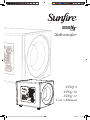
Subwoofer
AGE SEL
ECTOR
VOLTAGE
SELEC
TOR
100-120
V
T10AL
250V
220-240
V
T6AL 250V
50/60 Hz,
900 W
9901375_Rev-A_Sunfire_XTEQ_User_Manual_0812_PRINT_ENG.indd 1
XTEQ 8
XTEQ 10
XTEQ 12
User's Manual
8/12/14 7:10 PM
Le symbole de l’éclair fléché dans un triangle
équilatéral, est destiné à alerter l’utilisateur de
la présence d’une “tension dangereuse” dans le
boîtier du produit qui peuvent être des ampleur
suffisante pour constituer un risque d’électrocution
aux personnes.
Ce symbole est destiné à alerter l'utilisateur de la
présence d'opération et de maintenance (entretien)
dans la documentation accompagnant l'appareil.
Important Safety Instructions
1. Read these Instructions.
Lisez et suivez ces instructions.
2. Keep these instructions.
Conservez ces instructions.
3. Heed all Warnings.
Respectez tous les avertissements.
4. Follow all instructions.
Suivez toutes les instructions.
5. Do not use this apparatus near water.
Ne pas utiliser cet appareil près de l'eau.
6. Clean only with a dry cloth.
Nettoyer uniquement avec
un chiffon sec.
7. Do not block any ventilation openings.
Install in accordance with the manufacturer’s
instructions.
Ne pas bloquer les ouvertures de ventilation.
Installer conformément aux instructions du
fabricant.
8. Do not install near any heat sources such
as radiators, heat registers, stoves, or other
apparatus (including amplifiers) that produce
heat.
Ne pas installer près de sources de chaleur
telles que radiateurs, registres de chaleur,
poêles ou autres appareils (y compris les
amplificateurs) produisant de la chaleur.
9. Do not defeat the safety purpose of the
polarized or grounding-type plug. A polarized
plug has two blades with one wider than the
other. A grounding-type plug has two blades
and a third grounding prong. The wide blade
or the third prong is provided for your safety.
If the provided plug does not fit into your
outlet, consult an electrician for replacement
of the obsolete outlet.
Ne détruisez pas la sécurité de la terre ou
polarisées - fiche. Une fiche polarisée possède
deux lames dont une est plus large que l'autre.
Si la fiche fournie ne rentre pas dans votre
prise, consultez un électricien pour remplacer
la prise obsolète.
10. Protect the power cord from being walked on
or pinched particularly at plugs, convenience
receptacles, and the point where they exit
from the apparatus.
Protégez le cordon d'alimentation d'être
piétiné ou pincé, particulièrement au niveau
des fiches, des prises, et le point où ils sortent
de l'appareil.
11. Only use attachments/accessories specified by
the manufacturer.
N'utilisez que des accessoires specifies par le
fabricant.
12. Use only with a cart,
stand, tripod, bracket,
or table specified by the
manufacturer, or sold with
the apparatus. When a cart
or rack is used, use caution
when moving the cart/apparatus combination
to avoid injury from tip-over.
Utilisez uniquement un chariot, stand, trépied,
support ou table spécifiés par le fabricant
ou vendu avec l'appareil. Quand un panier
ou rack est utilisé, faites attention lorsque
vous déplacez l'ensemble chariot / appareil,
pour éviter d'éventuelles blessures en cas de
chute.
13. Unplug this apparatus during lightning storms
or when unused for long periods of time.
Débranchez cet appareil pendant les orages
ou lorsqu'il n'est pas utilize pendant de
longues périodes de temps.
14. Refer all servicing to qualified service
personnel. Servicing is required when
the apparatus has been damaged in any
way, such as power-supply cord or plug is
damaged, liquid has been spilled or objects
2
9901375_Rev-A_Sunfire_XTEQ_User_Manual_0812_PRINT_ENG.indd 2
User's Manual
8/12/14 7:10 PM
al
have fallen into the apparatus, the apparatus
has been exposed to rain or moisture, does
not operate normally, or has been dropped.
Confiez toute réparation à un personnel
qualifié. Une réparation est nécessaire lorsque
l'appareil a été endommagé de quelque façon
que ce cordon d'alimentation ou la fiche est
endommagé, liquide a été renversé ou des
objets sont tombés dans l'appareil, l'appareil
a été exposé à la pluie ou à l'humidité, ne
fonctionne pas normalement, ou s'il est tombé.
15. The mains plug (appliance coupler) is used as
the disconnect device, the disconnect device
shall remain accessible and operable at all
times.
La fiche d'alimentation (appareil coupleur)
est utilisé comme dispositif de déconnexion,
le dispositif de déconnexion doit rester
facilement accessible.
16. To completely disconnect this apparatus from
the AC Mains, disconnect the power supply
cord plug from the AC receptacle.
Pour déconnecter complètement cet
appareil du secteur, débranchez le cordon
d'alimentation de la prise murale.
17. Open flame sources, such as lighted candles,
should NOT be placed on the apparatus.
Aucene source de flamme nue, telle que
des bougies allumées, ne doit être placé sur
l'appareil.
18. The apparatus should be connected to a
main socket outlet with a protective earthing
connection.
Borne de terre de protection. L'appareil doit
être connecté à une prise secteur avec une
prise de terre.
FCC Required Text:
NOTE: This equipment has been tested and
found to comply with the limits for a Class B digital
device, pursuant to part 15 of the FCC Rules.
These limits are designed to provide reasonable
protection against harmful interference in a
residential installation. This equipment generates,
uses, and can radiate, radio frequency energy
and, if not installed and used in accordance with
the instructions, may cause harmful interference
to radio communications. However, there is no
guarantee that interference will not occur in a
particular installation. If this equipment does
cause harmful interference to radio or television
reception, which can be determined by turning the
equipment off and on, the user is encouraged to
try to correct the interference by one or more of the
following measures:
•
•
•
•
Reorient or relocate the receiving antenna.
Increase the separation between the
equipment and receiver.
Connect the equipment into an outlet on
a circuit different from that to which the
receiver is connected.
Consult the dealer or an experienced radio/
TV technician for help.
Changes or modifications not expressly approved
by the party responsible for compliance could void
the user's authority to operate the equipment.
Table of Contents
Safety Instructions..........................2
Introduction................................4
Unpacking and Care.......................4
Control Panel Features...................6
Installation............................8
Connections.........................9
Location...................................10
Room Equalization Procedure......12
System Configurations.................14
Specifications..........................18
Troubleshooting Guide..................20
Limited Warranty...........................22
Service Assistance.......................23
To find out more about this and other Sunfire products, please visit our website: www.sunfire.com
User's Manual
9901375_Rev-A_Sunfire_XTEQ_User_Manual_0812_PRINT_ENG.indd 3
3
8/12/14 7:10 PM
Introduction
Care
Thank you for purchasing this Sunfire XTEQ
Subwoofer. The big breakthrough features
of the subwoofer are its innovate tracking
down converter amplifier, its long throw,
high back-electromotive force driver, and
its fully automatic room equalizer. Taken
together, these unique features provide this
subwoofer with as much bass as you would
get from several 15 inch drivers mounted in
a cabinet the size of a small refrigerator.
To maintain the speaker cabinet’s finish, first
unplug the power cord and then use a soft
cloth to clean the surfaces. If your Sunfire
Subwoofer needs servicing, please read the
Troubleshooting section of this document.
Unpacking
Your Sunfire Subwoofer should reach you
in perfect condition. If you do notice any
shipping damage, please contact your
Sunfire Dealer immediately. Gently lift
out the unit and remove all the packing
material. It is important to save all the
packing materials and the box in case your
subwoofer ever needs to be moved or
shipped for repair.
If a problem persists, contact your
nearest authorized Sunfire Dealer
or Sunfire Technical Support at:
Toll Free: 800.622.3526
Email: [email protected]
Web: http://sunfire.com/support.asp
What's included
1 XTEQ subwoofer
1 US STD IEC line cord
1 Microphone with cable
1 Microphone stand
Make sure that you keep your sales receipt.
It is the only way to establish the duration of
your Limited Warranty and it may come in
useful for insurance purposes.
Please take a moment to record the serial
number, place of purchase and purchase
date on the following card so that you may
keep this information with your packaging
should you need to refer back to it at a later
time.
Serial Number:
Purchased from:
Date:
4
9901375_Rev-A_Sunfire_XTEQ_User_Manual_0812_PRINT_ENG.indd 4
User's Manual
8/12/14 7:10 PM
al
Control Panel Features
1
2
3
4
5
1. Crossover Frequency
3. Phase Control
Rotate the control until the bass sounds
natural. If the mid-bass sounds natural but
you want more low bass, turn this control
down a little, then turn the Level control up
by about the same amount. This increases
the low-bass output while leaving the midbass output the same.
4. Trigger Input
This control changes the high frequency
cutoff point. With the control set to 100 Hz,
the subwoofer will reproduce frequencies
up to 100 Hz. If the control is set fully
clockwise, the crossover is bypassed
and the subwoofer will reproduce a wide
frequency range. With the control fully
counter-clockwise the subwoofer reproduces
a narrow range, up to 30 Hz.
2. Level
This control lets you match the output
level of the subwoofer to the level of your
other speakers. The subwoofer output will
increase as this control is rotated clockwise.
When you initially install this subwoofer in
your system, turn this down before turning
on your subwoofer. This will prevent any
loud surprises.
This control changes the relative phase
of the subwoofer with respect to the other
speakers. Use this control to help blend the
subwoofer with the rest of the system. This
is accomplished by adjusting the control in
small increments as you listen for the most
bass at your listening position. As a final
trim, readjust the Crossover Frequency and
volume controls after the Phase has been set.
The trigger input can be used to
automatically turn on the subwoofer from
Standby mode. To do this, connect +12
VDC to the positive (+) terminal, and
ground to the negative (–) terminal. Many
of the currently available high quality Home
Theater Receivers and Preamplifiers have
matching12 VDC Trigger outputs. When
they are turned on, the subwoofer will “be
triggered” to turn on.
5. Line Level Inputs
Connect these unbalanced inputs with RCA
type patch cords to the line level outputs of
your receiver or preamp. If your preamplifier
or receiver has a single sub/LFE output,
connect it to either input jack.
User's Manual
9901375_Rev-A_Sunfire_XTEQ_User_Manual_0812_PRINT_ENG.indd 5
5
8/12/14 7:10 PM
Control Panel Features Continued
13
14
15
16
17
6
8
7
9
10
12
11
6. Line Level Outputs
Line level output signals are available
at these jacks. These outputs are active
whenever a signal is hooked up to the
inputs of the subwoofer. The outputs are
not affected by the volume level, phase,
frequency control, or EQ of the subwoofer.
To use the outputs, connect the preamp
outputs on your preamp receiver to the
subwoofers line level inputs using goodquality RCA type patch cords. Then connect
a second set of patch cords from the
subwoofer outputs to the line level inputs
of your main amplifier. The adjacent output
switch (7) allows the outputs to be either
high pass, or full range.
8. Output Switch
This switch affects the frequency range of
the line level outputs.
In the bypass position, the outputs are a full
range copy of the input signals.
In the 85 Hz position, the outputs are a copy
of the input signals with the frequencies
below 85 Hz removed. We recommend
using this position if your speakers are not
designed to reproduce low frequencies.
If your main speakers are capable of
operating at full frequency range (20Hz to
20kHz), then use the bypass position.
9. Slave Input and Output
7. Balanced (XLR) Input
These connections simplify the hook up and
operation of two XTEQ subwoofers.
Balanced connections offer superior
noise cancellation over unbalanced type
connections.
Connect the Slave output from the first
subwoofer to the slave input of the second.
The second subwoofer will then receive the
optimum audio signals from the first, and
there is no need to adjust the controls of the
second subwoofer, as the audio is controlled
by the controls and EQ setting up the first.
Use this balanced input to connect to the
XLR balanced connection line-level output
on select Home Theater preamplifiers or
other sources.
6
9901375_Rev-A_Sunfire_XTEQ_User_Manual_0812_PRINT_ENG.indd 6
User's Manual
8/12/14 7:10 PM
al
The second subwoofer will not require any
connections to its line level inputs, as it
receives the audio through its slave input.
10. Power Switch
The power switch is used for installing
and uninstalling the subwoofer, and for
power conservation during long vacations.
Leave it switched on at all times for normal
operation.
After a period of inactivity, i.e. with no input
signal, the subwoofer will automatically turn
itself to standby mode, where it is effectively
muted. It can turn back on automatically
when an input signal is applied, or if a 12
VDC trigger voltage is applied to the trigger
inputs, or if the start button is pressed.
ONLY MAKE THIS ADJUSTMENT IF THE
SUBWOOFER WILL BE CONNECTED
TO A VOLTAGE SUPPLY OF BETWEEN
220~240VAC @50Hz.
Incorrect setting of this switch can
cause catastrophic circuit failure.
13. EQ LED
This LED provides feedback during
the Room EQ procedure. It also lights
continuously whenever the subwoofer
is not in standby.
14. Start Button
Used to initiate the automatic Room EQ
procedure. See page 12 for complete details
on the Room EQ procedure.
11. IEC Line Cord Socket and 15. EQ On/Off Switch
Fuseholder
This switch is used to turn the EQ on or off.
The subwoofer comes with a detachable line It allows you to easily judge the effect of the
cord that connects here. Be sure to use the
EQ on the subwoofer performance.
linecord approved for your region / location.
The subwoofer is supplied with a
conservative slow blow type fuse to protect
the electronics.
16. Microphone Input
This is the input connection for the supplied
linear measurement microphone used during
the automatic EQ calibration procedure.
Always unplug the power cord before
inspecting or changing the fuse. Never use a 17. Power LED
fuse with a larger current rating than shown
This red LED indicates when the subwoofer
on the markings next to the fuseholder.
is connected to AC power. When a 12 V
trigger voltage or an audio signal is applied,
this LED goes out and the blue EQ LED
12. Line Voltage Selector
lights up.
Switch
This switch allows the subwoofer to be
set to the local region AC mains voltage.
The AC voltage option has been factory
configured for 100~120v. Should the AC
voltage need to be changed to 220~240v,
please complete the following steps:
Always unplug the power cord and all other
connections, before moving this switch.
Loosen the screw on the protective cover,
slide the cover away and the slide switch
can be adjusted. Make sure to replace the
protective cover when done.
User's Manual
9901375_Rev-A_Sunfire_XTEQ_User_Manual_0812_PRINT_ENG.indd 7
7
8/12/14 7:10 PM
Installation
Observe the following general precautions
and read the safety instructions on pages
two and three before using your Sunfire
subwoofer.
•
•
•
Never open the cabinet or remove the
middle Control Panel as this might
result in electrical shock to you or
damage to the unit.
Protect it from prolonged exposure to
direct sunlight and other direct sources
of heat, such as heating vents and
radiators.
To prevent fire or shock do not expose
the unit to rain or moisture. If fluid or
a foreign object should enter the unit,
immediately turn off the power and
contact your Sunfire dealer.
AC Power Considerations
•
Ensure that the unit is plugged into an
outlet capable of supplying the correct
voltage and amperage specified for
your model.
US (120 VAC) Model – The outlet must have a circuit rating of 8 amps or more (a typical home circuit is rated at 15 amps).
EURO (240 VAC) Model – The outlet must have a circuit rating of 6 amps of more.
•
Unplug your sub woofer's power cord
from the electrical outlet if it will be left
unused for a long period of time.
•
Route the power supply cord so it is
not likely to be walked on or pinched
by items placed upon or against it,
especially at plugs, convenience
receptacles, and the point where it
exits from the unit.
•
Avoid excessive exposure
to extreme cold or dust.
•
Do not place heavy objects
on top of the unit.
•
Do not place the subwoofer with
its control panel against the floor.
Magnetic Fields
•
To move the subwoofer along the
floor, rotate it onto one edge on a
plastic sheet or bag and it will slide
along easier.
•
Heat Rise
•
Allow adequate ventilation around the
middle control panel of the subwoofer.
•
Do not let anything come into contact
with the panel and keep at least
2 inches away from any walls.
•
The metal bottom plate serves
as the amplifier heat sink and also
as a conduit to remove internal heat
to the outside.
8
9901375_Rev-A_Sunfire_XTEQ_User_Manual_0812_PRINT_ENG.indd 8
We recommend that you place your
subwoofer further than 2 feet away
from other electronic products that may
be susceptible to magnetic fields so the
speaker magnet won't damage your
existing devices. Examples of such
items; video and/or audio magnetic
tape, computer and/or DVR type
memory storage drives, including USB,
Compact Flash, SD Cards, etc. . .
User's Manual
8/12/14 7:10 PM
al
Connections
Please consider the following
when setting up your new system:
•
•
•
Before making or changing any
connections, always make sure that the
subwoofer and your other components
are turned off. Also turn down the
•
volume control of the subwoofer and
your preamplifier or receiver.
This diagram shows all of the low-power
components sharing a power strip which
is connected to the same outlet by the
amplifier.
•
Media Server
Blu-Ray
•
The subwoofer is connected to an outlet
on the same circuit breaker, provided
that the total system current draw does
not exceed the breaker current rating.
•
This arrangement will reduce the
possibility of an audible hum in your
system caused by a ground loop.
User's Manual
9901375_Rev-A_Sunfire_XTEQ_User_Manual_0812_PRINT_ENG.indd 9
Whenever possible, keep the power
cords away from the signal cables
or speaker wires to prevent any hum
or interference being heard in
the speakers.
Choose reliable high-quality
interconnect cables, also called patch
cords or RCA cables. They should be
fully shielded and as short as possible
for the job. The longest cable in your
system will likely be to the subwoofer,
so choose a good quality brand.
Some patch cords can be a very tight
fit and there is usually a preferred
method of getting them on and off.
Some have to be removed with a
twisting action. Be gentle or you may
damage the jacks of the subwoofer
or your other components.
9
8/12/14 7:10 PM
Location
Your subwoofer is designed / optimized to
be placed in a room corner on the diagonal
(corner loading), but can also be optimized
for other room option placements.
The following are additional
recommendations that Sunfire has found to
be beneficial in finding the prime location for
your subwoofer:
•
Experiment with at least two places
and decide which is the best for your
enviroment:
•
Start by placing the
subwoofer right on the seat of
your favorite couch or easy
chair. Take care to position it
so it is not likely to fall off.
•
If you are using the subwoofer
as part of a home theater
system, you can either run a
calibration test signal through the subwoofer, or simply plug
the analog outputs of a
CD/DVD/Blu-Ray player
directly into the subwoofer's
line level inputs. Turn down
the subwoofer’s volume level
before turning on the audio
source, then play some of
your favorite music samples
with heavy bass.
•
Walk around the room, listening, and
stand in all the positions where you
might be able to place the subwoofer.
Try crouching down, and try the
corners. Find a place for the subwoofer
where the bass output sounds the
loudest.
•
Shut things down and install the
subwoofer in this position. Make
sure the control panel is not touching
anything, and that it can receive good
ventilation.
•
Although low frequencies are
non-directional, factors such as room
reflections, standing waves, resonance
and absorption will strongly affect your
subwoofer's performance. Moving the
subwoofer from one location to another
can have a major effect on the bass
response.
•
The auto EQ mode will let you adjust
for the room effects, but you should find
the best location first.
Remember to keep the subwoofer
at least two or 3 feet away from other
electronics that may be negatively
impacted by strong magnetic fields.
This will reduce the chance of the
magnetic fields upsetting or erasing
your magnetic media.
10
9901375_Rev-A_Sunfire_XTEQ_User_Manual_0812_PRINT_ENG.indd 10
User's Manual
8/12/14 7:10 PM
al
Using Two Subwoofers
•
If you wish to use two subwoofers, the
sound output will double - an increase
of 3 DB. Locate the subwoofers with
one in each corner and experiment
with the location and phase control to
achieve the best bass response.
With two subwoofers you’ll experience
more balanced bass and fewer high
and low spots.
•
Use the slave input and output
connections if you are using two
XTEQ subwoofers.
Now that you have found a proper location
in your room for your subwoofer(s), it is time
to perform the Room Equalization Procedure
to maximize your subwoofer(s) full potential.
The Sunfire XTEQ unitizes the most current
and advanced auto equalization system
available.
As you found in the last exercise, 'Location',
subwoofer performance is greatly affected
by the room in which it is situated, and the
positioning within the room. The “Room
Effects” will boost and cut the output levels
reaching your listening position. This gives
a “Room EQ” effect which can often be far
from wonderful.
The Sunfire XTEQ can automatically adjust
for the effects of Room EQ. The XTEQ
will measure the actual room frequency
response using the supplied measurement
microphone and on-board processor test
tone generator. After “listening” to the
room at many different key subwoofer
frequencies, the XTEQ then automatically
compensates for peaks or dips and smooths
out the subwoofer(s) response to maximize
your entertainment enjoyment.
User's Manual
9901375_Rev-A_Sunfire_XTEQ_User_Manual_0812_PRINT_ENG.indd 11
11
8/12/14 7:10 PM
Room Equalization Procedure
Instructions for Auto EQ:
To utilize effectively, please follow
the steps outlined below:
•
Plug in the XTEQ and turn on the power
using the power switch on the back
panel of the system.
1. Install the subwoofer in the best location
for your room (see previous section).
•
Please make sure that the microphone
(supplied) is attached through the
microphone input in the back panel
of the box.
2. The calibration must be done while the
listening room is quiet. Please turn off
any noisy machinery, including heating
or cooling systems during this process.
•
The power indicator will turn red and
confirm that it is “on”.
•
In order to continue with the Auto EQ
process, you’ll have to take the system
out of standby mode.
3. Place the microphone in the listening
position (on the couch, for example),
pointing in the direction you’ll normally
be facing while listening to your system.
Only use the microphone supplied by
Sunfire for this process.
•
To do so, press the start button again.
•
4. Plug the microphone into the
subwoofer’s microphone jack (MIC
The Power LED indicator should turn off.
Input) located on its back panel.
To Launch the
Auto EQ Process:
•
Push start.
•
The LED indicator will turn blue in color.
•
The system will generate a set of tones
and will automatically adjust the proper
level at four seperate frequencies.
(The four frequencies are 35Hz,
49Hz, 64Hz, 84Hz.)
•
When finished the blue light will turn off.
5.Back panel controls and connections
should be set as the following:
a. Nothing should be connected
to any of the Input connection
terminals (Left / Right or XLR)
b. Level should be set to “0” dB.
c. Crossover should
be set to “Bypass”.
d. Phase should be set to “0”.
e. EQ ON/OFF should be
switched to “ON”.
When configuring Auto or Manual EQ,
positioning the Auto EQ button to “on” will
enable you to create your own preferred
settings instead of using factory settings.
VOLTAGE
SELECTOR
100-120
V
T10AL
250V
220-240
V
T6AL 250V
50/60 Hz,
12
9901375_Rev-A_Sunfire_XTEQ_User_Manual_0812_PRINT_ENG.indd 12
900 W
User's Manual
8/12/14 7:10 PM
al
•
When you are finished, you may remove
the microphone from the mic input.
•
Leave the Auto EQ switch in the
“EQ On” position to use the settings
that you just configured. If at any time
you’d like to default to factory settings,
turn the Auto EQ switch to “EQ off.”
To Manually Adjust EQ:
Should you wish, you may also manually
adjust the level of the 4 seperate
frequency tones (35Hz, 49Hz, 64Hz,
84Hz) by following these steps:
•
Plug in the XTEQ and turn on the
power using the power switch on
the back panel of the system.
•
The power indicator will turn
red and confirm that it is “on”.
•
Hold the start button for 5 seconds.
•
A tone will be heard.
•
You can now manually adjust the volume
level for that given frequency tone.
•
Then, push the start button and it will
store that level for that frequency.
•
Press start again, and you will move
on to the next frequency tone and
follow the same steps four times at
the four different frequencie tones.
•
When all frequencies have been
adjusted to your liking, press and hold
the start button until the unit shuts off.
•
Leave the Auto EQ switch in the
“EQ on” position to use the settings
that you just configured. If at any time
you’d like to default to factory settings,
turn the Auto EQ switch to “EQ off.”
If I am using two XTEQ subwoofers,
What is the procedure for the Room
Equalization?
1.
If you are using two XTEQ subwoofers,
make sure that they are connected
using the SLAVE output of the first sub
to the SLAVE input of the second.
2.Back panel connections and controls
should be set to the following on the
'slave' subwoofer:
a. Nothing should be connected
to any of the Input connection
terminals (Left / Right or XLR).
b. Level should be set to “0” dB.
c. Crossover should be set
to “Bypass”.
d. Phase should be set to “0”.
e. EQ ON/OFF should
be switched to “ON”.
3. Connect the microphone to the
primary unit only.
4. Follow the procedure for Room
Equalization for one subwoofer (shown
above). The EQ room measurement will
take into account the sound from both
subwoofers, and the EQ adjustment will
affect both subwoofers.
My AV Receiver has an Auto Calibration
and microphone procedure with its
set-up process. Which EQ / Calibration
system should I use?
Sunfire recommends that you use BOTH –
the Sunfire Auto Room Equalization AND
your AV receiver’s Auto Calibration System.
For optimum performance, start with the
Sunfire Auto Room Equalization procedure.
Then make your connection between
the Sunfire XTEQ and your AV Receiver.
Then follow the AV Receiver’s instructions
for its Auto Calibration System.Using this
alignment of steps ensures that the XTEQ is
first EQ’d to your room and then calibrates
all of your speakers including the XTEQ to
maximize your experience.
User's Manual
9901375_Rev-A_Sunfire_XTEQ_User_Manual_0812_PRINT_ENG.indd 13
13
8/12/14 7:10 PM
System Configurations
The following pages show some typical connections that you might make in your
installation. They show how the inputs and outputs of the Sunfire Subwoofer are
connected to your preamplifier or AV receiver.
Connections to a Preamplifier’s Subwoofer Output
If your AV Receiver / Preamplifier has a subwoofer output (often labeled LFE for Low
Frequency Effects), it can be connected to the subwoofer’s left or right input as shown.
This is the simplest and recommended connection. An AV Receiver with a sub/LFE output
can be connected in the same way.
The subwoofer will play the low frequency range and the other speakers will play the
frequency range delivered to them by your amplifier.
Your AV Receiver / Preamplifier may have an independent subwoofer volume control.
Make sure this is correctly adjusted, and that the Sunfire Subwoofer’s crossover frequency
is set to 100 Hz. This is by no means an ironclad rule, rather it is a good starting point.
(Refer to the crossover frequency control details within this document, as well as your
AV Receiver / Preamplifier User’s Manual.)
You can set the subwoofer’s level control
to 0 dB, and then use the preamplifier’s
subwoofer level control for normal and
routine adjustments.
VOLTAGE
SELECTOR
100-120
V
T10AL
250V
220-240
V
T6AL 250V
50/60 Hz,
14
9901375_Rev-A_Sunfire_XTEQ_User_Manual_0812_PRINT_ENG.indd 14
900 W
User's Manual
8/12/14 7:10 PM
al
Connections to a Preamplifier Using "Y" Cables
If your preamplifier does not have a dedicated sub/LFE output, you can use “Y” cables to
send its main outputs to both the subwoofer and your amplifier.
The subwoofer will play the low frequency range and your front speakers will play the
full range. Although bass is commonly distributed evenly between left and right channels
(L+R bass), movie soundtracks often contain differential (L-R) bass. The opening scene in
“Transformers”, for example, has loads of L-R bass information. If this is not preserved, the
bass in these scenes sounds anemic. Therefore, systems which do not have a dedicated
sub/LFE output should use both the left and the right inputs as shown, for the greatest
bass impact.
An alternative connection method without using Y cables is shown on the next page.
If your preamp/receiver has a dedicated sub/LFE output,
then only one input is used as shown on the previous page.
VOLTAGE
SELECTO
R
100-120
V
T10AL
250V
220-240
V
T6AL 250V
50/60 Hz,
User's Manual
9901375_Rev-A_Sunfire_XTEQ_User_Manual_0812_PRINT_ENG.indd 15
900 W
15
8/12/14 7:10 PM
Using the Line-Level Outputs
If you are using a preamplifier that does not have a sub/LFE output, you can send its
left and right front output into the subwoofer’s line-level inputs and then connect the
subwoofer’s line-level outputs to the inputs of your amplifier.
The subwoofer will play the low frequencies and your amplifier and front speakers
will play the frequency range of the subwoofer's outputs.
The subwoofer's output switch lets you select BYPASS or 85 Hz.
In the 85 Hz position, the signals coming out of the subwoofer’s outputs are a copy of the
signals going into the subwoofer, except that the low bass is filtered out. This uses the
subwoofer’s passive crossover network, rather than the active network and controls.
This is an excellent method if your front speakers are small satellites or mini-monitors,
and/or your power amplifier is of limited power, such as a tube amp.
If the switch is set to BYPASS, then the amplifier and speakers receive the full frequency
range. This is a good position if your speakers are capable of good low frequency
performance.
VOLTAGE
SELECTO
R
100-120
V
T10AL
250V
220-240
V
T6AL 250V
50/60 Hz,
16
9901375_Rev-A_Sunfire_XTEQ_User_Manual_0812_PRINT_ENG.indd 16
900 W
User's Manual
8/12/14 7:10 PM
al
Using the Slave Input and Output
The SLAVE output from one XTEQ subwoofer can be connected to the SLAVE input of
a second XTEQ subwoofer. The second subwoofer will then receive the optimum audio
signals from the first.
There is no need to adjust the controls of the second subwoofer, as the audio is controlled
by the controls and EQ setting of the first. The second subwoofer does not require any
connections to its line-level inputs.
Before the EQ procedure, make sure that both XTEQ subwoofers are connected together
as shown. The microphone should be connected to the first subwoofer. The automatic EQ
procedure will take into account the effect of both subwoofers as they play in the room.
VOLTAG
E SELECT
OR
100-12
0V
T10AL
250V
220-24
0V
T6AL 250V
50/60 Hz,
900 W
VOLTAG
E SELEC
TOR
100-120
V
T10AL
250V
220-240
V
T6AL 250V
50/60 Hz,
User's Manual
9901375_Rev-A_Sunfire_XTEQ_User_Manual_0812_PRINT_ENG.indd 17
900 W
17
8/12/14 7:10 PM
Specifications
MODEL
XTEQ8
XTEQ10
XTEQ12
Driver Complement
8” Active Side
Firing Driver
8” Side Firing
Passive Radiator
10” Active Side
Firing Driver
10” Side Firing
Passive Radiator
12” Active Side
Firing Driver
12” Side Firing
Passive Radiator
Amplifier Power
1,800 Watt
Tracking Down Converter
2,700 Watt
Tracking Down Converter
3,000 Watt
Tracking Down Converter
Frequency Response
22Hz – 100Hz
18Hz – 100Hz
16Hz – 100Hz
THD
Less than
3% typical operation
Less than
3% typical operation
Less than
3% typical operation
High Pass Crossover
85Hz
85Hz
85Hz
Low Pass Crossover
30Hz
30Hz
30Hz
Phase
0 to 180 degree (variable)
0 to 180 degree (variable)
0 to 180 degree (variable)
Woofer Magnet
6.3” x 2.75” Deep
143 oz.
7.5” x 3.5” Deep
194 oz.
7.5” x 3.5” deep
194 oz.
Voice Coil
2”
3”
3”
Cone Material
Non-pressed paper with a
high density foam edge
Non-pressed paper with a
high density foam edge
Non-pressed paper with a
high density foam edge
Line Level (L&R)
Line Level (RCA)
Nominal Impedance 15k Ω
Line Level (RCA)
Nominal Impedance 15k Ω
Line Level (RCA)
Nominal Impedance 15k Ω
Input (Mono)
Balanced (XLR)
Nominal Impedance 14k Ω
Balanced (XLR)
Nominal Impedance 14k Ω
Balanced (XLR)
Nominal Impedance 14k Ω
Slave
Line Level - Mono (RCA)
Nominal Impedance 8k Ω
Line Level - Mono (RCA)
Nominal Impedance 8k Ω
Line Level - Mono (RCA)
Nominal Impedance 8k Ω
Microphone 3.5 mm
(condense mic incl.)
3.5mm
(Microphone included)
3.5mm
(Microphone included)
3.5mm
(Microphone included)
Trigger On (use ATMOS spee)
12 VDC
12 VDC
12 VDC
Thru (L&R)
Line Level (RCA)
85Hz High Pass Filter /
Bypass - selectable
Line Level (RCA)
85Hz High Pass Filter /
Bypass - selectable
Line Level (RCA)
85Hz High Pass Filter /
Bypass - selectable
Slave
Line Level – Mono (RCA)
Nominal Impedance 120k Ω
Line Level – Mono (RCA)
Nominal Impedance 120k Ω
Line Level – Mono (RCA)
Nominal Impedance 120k Ω
Finish
High Gloss Black
High Gloss Black
High Gloss Black
Included Accessories
Microphone and
Power Cord
Microphone and
Power Cord
Microphone and
Power Cord
Dimensions (H/W/D) - Net
9" x 9" x 9"
11" x 11" x 11.25"
13" x 13" x 12.25"
Weight Net
29 Lbs.
55 Lbs.
60 Lbs.
Power
100-120 / 220-240 V~,
50/60Hz, 900W
100-120 / 220-240 V~,
50/60Hz, 900W
100-120 / 220-240 V~,
50/60Hz, 900W
INPUTS
OUTPUTS
GENERAL
18
9901375_Rev-A_Sunfire_XTEQ_User_Manual_0812_PRINT_ENG.indd 18
User's Manual
8/12/14 7:10 PM
al
VOLTAGE
SELEC
TOR
100-120
V
T10AL
250V
220-240
V
T6AL 250V
50/60 Hz,
900 W
User's Manual
9901375_Rev-A_Sunfire_XTEQ_User_Manual_0812_PRINT_ENG.indd 19
19
8/12/14 7:10 PM
Troubleshooting
The Sunfire Subwoofer is expertly designed
and built to provide years of trouble-free
performance. Most problems that occur can
usually be solved by checking your setup or
making sure that the components connected
to the amplifier are on and fully operational.
The following information will help you deal
with common problems you may experience
during normal use. If a problem still persists,
please contact your Sunfire Dealer for
assistance.
Not Enough Bass
•
•
•
•
•
•
If the preamplifier’s subwoofer/LFE
output has an adjustable crossover
frequency, make sure that the Sunfire
subwoofer’s own crossover point is set
higher or part of the bass range will be
missing.
Not Enough Bass
in a 5.1 System
•
Check that your preamplifier’s outputs
are connected to the subwoofer’s
line-level inputs and not to the linelevel outputs. If they are connected to
the outputs by mistake, the bass will
be weak but the subwoofer will still
function.
If your preamplifier has a single
subwoofer/LFE output jack, try using
a "Y" cable to connect it to the left and
right inputs.
Make certain the subwoofer is in a
•
corner location, firing at 45 degrees
into the walls formed by the corner.
This is not absolutely essential, but will
maximize the bass output and give the
smoothest possible response. If you
place the unit so one of the drivers is
firing into one of the walls, leave three
inches of clearance between the driver •
and the wall.
Home Theater preamplifiers usually
have a way of adjusting the level of the
subwoofer/LFE output, either using a
remote control or with a small volume
•
knob on the back panel. Make sure that
this is adjusted correctly.
Check that your preamplifier or
receiver’s sub output is turned on.
Some systems only have a sub output
signal when the front speakers are set
to “small.”
20
9901375_Rev-A_Sunfire_XTEQ_User_Manual_0812_PRINT_ENG.indd 20
5.1 Home Theater preamplifiers usually
have a bass management system
which allows the bass to be redirected
among your speakers. For example,
the bass normally present in the front
speakers can be redirected to play in
the subwoofer, or the subwoofer can
play the bass from all the speakers,
in addition to its dedicated LFE (low
frequency effects) channel. Make
sure that all of the bass management
options are correctly set. The
preamplifier may have a way of turning
the subwoofer output off entirely, so
check that it is always on.
Check that the preamplifier calibration
procedure is correctly adjusted.
Usually, the preamp will send a test
tone through all the speakers in your
system, allowing you to adjust (trim) the
volume of each channel until they are
all playing at the same level.
If the bass is weak only when playing
5.1 surround sources, check that your
preamplifier is correctly set to decode
the 5.1 surround modes, such as Dolby
Digital or DTS.
DVD & Blu-ray discs have a menu
which allows you to select which
soundtrack to play. Check that the
correct 5.1 surround audio soundtrack
is selected, otherwise it may just play
stereo into your preamp and you
won’t get the true LFE signal into the
subwoofer.
User's Manual
8/12/14 7:10 PM
al
Hum
where they first enter the room, so
they are making no connection to
your preamplifier, TV, or any other
component. If the hum is caused by
the cable TV line, then you will need
a “ground-loop isolator.” This is an
inexpensive device fitted in line with the
coaxial cable feed.
Adding any component such as a subwoofer
to an existing system will often give rise to
a hum which wasn’t there before. Your first
thought may be that the subwoofer has a
problem, but this is more than likely caused
by a “ground-loop” in your system.
Follow these steps to isolate the main cause
of the ground-loop hum (there may even be
more than one cause).
•
Try to have all of your equipment on
the same electrical outlet or circuit, see
page 9 for more details.
•
If your subwoofer is a fair distance
away from your other equipment, you
may use a 15 amp extension cord as
long as it has a ground connection.
NOTE: Never remove the ground
pin from any power cords. This is
very dangerous.
•
Turn off all components in your system,
including the subwoofer, amplifiers and
the preamplifier, before disconnecting
or connecting cables.
•
First remove every connection from the
subwoofer to the rest of your system.
Plug the subwoofer power cord back in
and check for the hum. If it is still there,
try plugging it into a different outlet in
case it is picking up interference on the
AC line.
•
•
•
If the hum persists, disconnect all the
source components one at a time from
the back of the preamplifier until you
identify the problem.
•
Ground-loop isolators are available
for audio lines and video. Once you
have identified which components
are causing a problem, you can fit the
isolators between the component and
the preamplifier.
No Auto Turn-off
The subwoofer should go into standby mode
after approximately fifteen minutes with no
audio signal present. If not, check there is
no background hum. The subwoofer may
sense hum as a small signal and stay on.
See the above hints to eliminate the hum.
No Auto Turn-on
The subwoofer should turn on (come out
of standby mode) when an audio signal is
applied, or 12 VDC is applied to the Trigger
inputs, or if the Start button is pressed. If it
does not then, check the following:
If you have followed the above
guidelines for the power connections
•
Check that the subwoofer power switch
and a hum is still present, then there
is on.
is one very common problem to
•
The subwoofer’s volume control
consider: a “ground-loop” introduced by
may be turned down, or no signal is
connecting a cable TV line to a DVD or
received from your preamplifier.
Blu-ray player, which is then connected
•
Check the input connections.
to the preamp. This can be addressed
•
Check the mode switch or menu on
as follows:
surround systems to be certain that
a bass signal is being sent to the
Disconnect all cables which come
subwoofer.
from outside the room, such as cable
TV, satellite TV, or roof top antennas.
•
Use the 12V Trigger for the most
Make sure that they are disconnected
reliable on/off operation.
User's Manual
9901375_Rev-A_Sunfire_XTEQ_User_Manual_0812_PRINT_ENG.indd 21
21
8/12/14 7:10 PM
Limited Warranty
Core Brands, LLC (“Core Brands”)
warrants to the original retail purchaser
only that this SUNFIRE XTEQ will be free
of manufacturing defects in material and
workmanship for the following period and
subject to the limitations and exclusions set
forth below:
Five years from the date of purchase
This warranty is not transferable to
subsequent purchasers of the product.
To obtain warranty service, contact the
authorized dealer where you purchased
your product or take the unit to the nearest
authorized SUNFIRE dealer (with proof of
purchase – claims made without proof of
purchase will be denied) who will test the
product and if necessary, forward it to
Core Brands for service. If there are no
authorized SUNFIRE dealers in your area,
you must contact Core Brands to receive
a factory Return Authorization Number.
DO NOT RETURN ANY UNIT WITHOUT
FIRST RECEIVING WRITTEN
AUTHORIZATION AND SHIPPING
INSTRUCTIONS FROM CORE BRANDS.
Upon examination, Core Brands will, at its
sole option and expense, repair or replace
any product found to be defective. Core
Brands will return the repaired or replaced
unit to you via its usual shipping method
from the factory to your address in the
United States of America or Canada only.
Any shipping costs for addresses outside
of the United States or Canada shall be
the responsibility of the purchaser. In the
event that this model is no longer available
and cannot be repaired effectively, Core
Brands, at its sole option, may replace it with
a different model of equal or greater value,
or refund the original purchase price paid.
THE FOREGOING ARE YOUR EXCLUSIVE
REMEDIES FOR BREACH OF WARRANTY.
This Warranty does not include service or
parts to repair damage caused by improper
use or handling, including but not limited to
damage caused by accident, mishandling,
improper installation, commercial use,
abuse, negligence, or normal wear and
tear, or any defect caused by repair to the
product by anyone other than Core Brands.
This warranty does not cover reimbursement
for your costs of removing and transporting
the product for warranty service evaluation,
or installation of any replacement product
provided under this warranty.
This Warranty will be void if:
The Serial Number on the product
has been removed, tampered with
or defaced.
The product was not purchased from
an authorized dealer or reseller.
THE FOREGOING WARRANTIES ARE
EXCLUSIVE AND IN LIEU OF ALL
OTHER EXPRESSED AND IMPLIED
WARRANTIES.
CORE BRANDS EXPRESSLY
DISCLAIMS ALL SUCH OTHER
WARRANTIES, INCLUDING BUT NOT
LIMITED TO IMPLIED WARRANTIES
OF MERCHANTABILITY, FITNESS
FOR A PAR TICULAR PURPOSE
AND NON-INFRINGEMENT, WITH
RESPECT TO THE PRODUCT.
TO THE MAXIMUM EXTENT PERMITTED
BY LAW, CORE BRANDS SHALL NOT BE
RESPONSIBLE FOR ANY INCIDENTAL
OR CONSEQUENTIAL DAMAGES
EXCEPT TO THE EXTENT PROVIDED
(OR PROHIBITED) BYAPPLICABLE LAW,
EVEN IF CORE BRANDS HAS BEEN
ADVISED OF THE POSSIBILITY OF
SUCH DAMAGES.
22
9901375_Rev-A_Sunfire_XTEQ_User_Manual_0812_PRINT_ENG.indd 22
User's Manual
8/12/14 7:10 PM
al
Notwithstanding the above, if you qualify as
a “consumer” under the Magnuson-Moss
Warranty Act, or applicable state laws,
then you may be entitled to any implied
warranties allowed by law for the Warranty
Period. Further, some states do not allow
limitations on how long an implied warranty
lasts or allow the exclusion or limitation of
consequential damages, so such limitations
may not apply to you. This warranty gives you
specific legal rights, and you may also have
other rights which vary from state to state.
Model ______________________________
Serial No. _______
____________________
Purchase Date _______________________
Service Assistance
For the name of your nearest
authorized SUNFIRE dealer, contact:
Core Brands, LLC.
1800 South McDowell Blvd
Petaluma, CA 94954
1-800-472-5555,
1-707-778-5733
or
www.sunfire.com
Please be advised that Core Brands only
sells its products via the Internet through a
select group of authorized Internet dealers.
These are listed on our website at
www.sunfire.com. Products offered on
the Internet through unauthorized Internet
dealers are not covered by the SUNFIRE /
Core Brands warranty and may be either:
1. Goods acquired on a secondary
or grey market
ATTENTION:
TO OUR VALUED CONSUMERS:
To insure that consumers obtain quality
pre-sale and after-sale support and service,
SUNFIRE products are sold exclusively
through authorized dealers. This warranty is
VOID if the products have been purchased
from an unauthorized dealer.
2. Counterfeit or stolen goods
3. Damaged, or defective goods
Please fill in your product information
and retain for your records.
User's Manual
9901375_Rev-A_Sunfire_XTEQ_User_Manual_0812_PRINT_ENG.indd 23
23
8/12/14 7:10 PM
VOLT
LTAGE
SELECTO
R
100-120
V
T10AL
250V
220- 24
0V
T6AL 25
0V
50/60 Hz
, 900 W
1800 South McDowell blvd, Petaluma, CA 94954
1-800-472-5555 • 1-707-778-5733
www.Sunfire.com
©2014 Core Brands, LLC. All rights reserved. Sunfire® is a registered trademark of
Corebrands, LLC, a Nortek company. All other trademarks are the property of their
respective owners. We reserve the right to change specifications, descriptions and prices
without notice. The technical and other information contained herein is not intended to set
forth all technical and other specifications. Designed and engineered in the USA.
Manual 9901375
9901375_Rev-A_Sunfire_XTEQ_User_Manual_0812_PRINT_ENG.indd 24
Rev A
8/12/14 7:11 PM