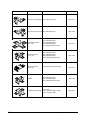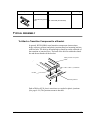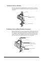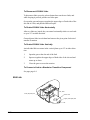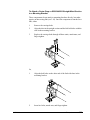
1
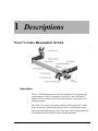
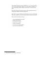
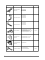
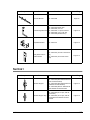
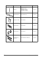
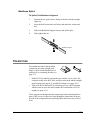
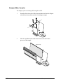
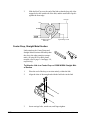
®
®
WAVETRAX
USER MANUAL
107719-2A0
WAVETRAX User Manual
Document Number 107719-1A0
Copyright© 2001, Telect, Inc., All Rights Reserved.
Telect® and Connecting the Future® are registered trademarks of Telect, Inc., 2111 N. Molter Rd., Liberty Lake,
Washington 99019
Technical Support:
By e-mail: [email protected]
By phone: 888-821-4856 or 509-921-6161
Note:
Telect assumes no liability from the application or use of these products. Neither does Telect convey any license under its patent rights nor the patent rights of others. This document and the products described herein are subject to
change without notice.
ii
Telect, Inc.
000000A0
Telect, Inc.
2111 N. Molter Rd.
P.O. Box 665, Liberty Lake, WA 99019
509-926-6000, 800-551-4567, Fax 509-926-8915
E-mail: [email protected] Internet: http://www.telect.com
Contents
1 Descriptions
2 Mounting/Support
Support......................................................................................... 2-2
Universal Bracket .................................................................. 2-3
Ladder-Rack Bracket ............................................................. 2-6
Extender Bracket.................................................................... 2-7
Below-Stringer Bracket ......................................................... 2-9
Adjustable Bracket............................................................... 2-11
Relay Rack Duct Extender Bracket ..................................... 2-12
Support Elements ....................................................................... 2-12
Allthread Support................................................................. 2-12
Allthread Support Clips ....................................................... 2-13
Backbone Support................................................................ 2-14
3 WaveTrax
Transition ..................................................................................... 3-1
Typical Plastic Assemblies .......................................................... 3-5
K124 Plastic Troughs: Connection to K124 Junctions & Transitions........................................................................................ 3-6
K64 Plastic Troughs: Connection to K64 Junctions, Transitions
& Links .................................................................................. 3-8
4 CableLinks
Links ............................................................................................ 4-1
Transition ..................................................................................... 4-1
Mounting...................................................................................... 4-7
Support......................................................................................... 4-8
Typical Assembly......................................................................... 4-9
To Attach a Transition Component to a Bracket ................... 4-9
To Attach a Link to a Bracket............................................. 4-10
To Attach a Link to a Metal Transition Component............ 4-10
To Attach a K64 Link or a Metal Transition Component to a
107719-2
Telect, Inc.
iii
Plastic Trough ...................................................................... 4-11
Links .......................................................................................... 4-11
K22, K44 Links.................................................................... 4-11
K64 Link .............................................................................. 4-12
Mounting Brackets..................................................................... 4-14
Universal Bracket ................................................................ 4-14
Ladder-Rack Bracket ........................................................... 4-16
Extender Bracket.................................................................. 4-17
Below-Stringer Bracket ....................................................... 4-19
Adjustable Bracket............................................................... 4-21
Relay Rack Duct Extender Bracket ..................................... 4-23
Support Elements ....................................................................... 4-23
Allthread Support................................................................. 4-23
Allthread Support Clips ....................................................... 4-24
Backbone Support................................................................ 4-25
Backbone Splice .................................................................. 4-27
Transitions.................................................................................. 4-27
Typical Transitions .............................................................. 4-28
Drop Reducer ....................................................................... 4-28
Adapter (Male, Female) ....................................................... 4-30
End Cap................................................................................ 4-31
Center Drop, Straight Metal Section.................................... 4-32
5 Service
Owner Maintenance ..................................................................... 5-1
In-Warranty Service ..................................................................... 5-1
Out-Of-Warranty Service............................................................. 5-1
Repacking For Shipment ............................................................. 5-2
iv
Telect, Inc.
107719-2
1 Descriptions
TELECT’S CABLE MANAGEMENT SYSTEM
Description
Telect’s Cable Management Systems are comprised of two separate, but
complimentary, series of components: WaveTrax™ and CableLinks™.
Both series use a common set of bracketing hardware components for installation support.
WaveTrax is a raceway system that combines solid troughs with various
forms of junctions, intersections, drops, reducers, and coupling components to provide high capacity, secure fiber optic cable routing between fiber distribution frames and fiber optic terminal equipment.
107719-2
Telect, Inc.
1-1
The complete WaveTrax system is available in 2, 4, 6, 8, and 12 inch (51,
102, 152, 203, and 305 mm) widths. The 2-inch width is available in a 2inch (51mm) depth; all other widths are provided in a 4-inch (102mm)
depth.
WaveTrax is designed to physically protect cable and allow for future re
configuration through retrofit able components.
WaveTrax1 is an open channel system allowing easy access to ensure that
fiber can be installed or removed without violating minimum bend radius.
WaveTrax has the following features:
•
•
•
•
•
Any desired length of run or drop
Bend radius protection
Snap-together channels
Totally reconfigurable
UL 94 V-0 fire-retardant plastic
•
No special tool requirements
1. This manual also covers the Telect’s CableLinks.
2
Mounting/Support
MOUNTING
Component
107719-2
Name
Part Numbers
Install Page
Universal K124 Bracket w/o Allthread
027-1000-12404
page<$chapnum> 7
Universal K124 Bracket With Allthread
027-1000-12409 (with M16 x 450mm
All-thread)
027-1000-12482 (with M16 x 600mm
All-thread)
page<$chapnum> 7
TRAX 12 Slim Universal Bracket
027-1000-12405
TRAX Slim Ladder
Rack Kit
027-1000-12406
TRAX Threaded Rod
Bracket Kit
027-1000-4051
027-1000-4251
Telect, Inc.
2-1
Component
Name
TRAX Center Below
Bracket Kit
TRAX C-Bracket Kit
TRAX L-bracket Kit
Install Page
027-1000-8450
027-1000-4252
027-1000-4052
027-1000-8453
027-1000-4253
027-1000-4053
027-1000-8454
027-1000-4254
027-1000-4054
Universal Bracket
027-1000-4204 (K22, 1-1/2” rail)
027-1000-4244 (K22, 2" rail)
027-1000-4004 (K44/K64, 1-1/2” rail)
027-1000-4044 (K44/K64, 2” rail)
2" Bracket and Kit
CableLinx
027-1000-4204 (K22, 1-1/2” rail)
027-1000-4244 (K22, 2" rail)
2" Universal Bracket
WaveTrax
027-2000-4205 (
Ladder Rack Bracket
2-2
Part Numbers
027-1000-4260 (K22)
027-1000-4060 (K44/K64)
Page 2-5
Page 2-7
Telect, Inc.
107719-2
Component
Name
Part Numbers
Install Page
Extender Bracket
027-1000-4005
Page 2-8
Below-Stringer Bracket
027-1000-4090, ladder rack
027-1000-4094, 3/4" rod
027-1000-4095, 1" square channel
027-1000-4096, 1/4" x 9/16" bar
027-1000-4098 (beneath floor)
Page 2-10
Adjustable Bracket
027-1000-4211
Page 2-13
Relay Rack Duct Extender Bracket
027-1000-4221 (for K22 or K44 Channel)
027-1000-4241 (for two K22 Channels)
Page 2-14
Part Numbers
Install Page
Allthread Support
027-1000-4006 (with allthread bar)
027-1000-4209 (with allthread bar and
K22 universal bracket)
027-1000-4009 (with allthread bar and
K44/K64 universal bracket)
027-1000-4082 (with 24" allthread bar
and K44/K64 universal bracket
Page 2-14
Allthread Support Clip
027-1000-4080 (for 3" span, with allthread bar)
027-1000-4081 (for 2" span, with allthread bar and K44/K64 universal
bracket
Page 2-15
SUPPORT
Component
107719-2
Name
Telect, Inc.
2-3
Component
Name
Part Numbers
Install Page
Allthread
106736 (1/2" x 18")
110093 (1/2" x 24")
118528 (M16 x 450mm)
118529 (M16 x 600mm)
Page 2-14
Backbone Support
027-1000-4091 (10')
Page 2-16
Backbone “J” Hooks
027-1000-4092
Page 2-16
Backbone Splice
027-1000-4093
Page 2-18
Backbone Mount
027-1000-4013
Page 2-16
6” Grid Mounting
Bracket Kit
027-1000-4490 (w/o Allthread)
Page 2-15
10'
2-4
Telect, Inc.
107719-2
MOUNTING BRACKETS
Universal Bracket
The two-piece Universal Bracket securely conK124
nects a CMS link or a transition component to a
½" or M16 allthread, 1½" or 2" ladder rack,
K44/K64
equipment rack, or wall. These instructions
show the larger, 4-slot bracket for mounting a
K44 or a K64 link. (The K22 mounts on a
shorter, 2-slot bracket, but the mounting sequence is the same. K124 transitions mount on a longer bracket, but again
the mounting sequence is the same.)
To Attach Bracket to an Allthread
1.
When using a metal bracket, cover allthread with the right rubber
tubing for its size to protect it where the bracket attaches.
2.
Align the two bracket pieces with the allthread between them. The
bracket can mount either lengthwise or crosswise on the allthread.
3.
Insert carriage bolts with the square shaft in the square holes of the
bracket back, attach nuts, and finger-tighten.
Rubber Tubing
Allthread
107719-2
Telect, Inc.
2-5
To Attach Bracket to a Ladder Rack
1.
Align the two bracket pieces with the ladder rack rail between
them. The bracket mounts only crosswise on the rail.
2.
Insert carriage bolts with the square shaft in the square holes of the
bracket back, attach nuts, and finger-tighten.
Ladder Rack
To Attach Bracket to an Equipment Rack
1.
Use only the front (L-shaped) bracket piece.
2.
Align the bracket with the holes in the equipment rack.
3.
Insert two screws and fully tighten.
Equipment Rack
To Attach Bracket to a Wall
1.
2-6
Use only the front (L-shaped) bracket piece.
Telect, Inc.
107719-2
2.
Insert appropriate anchors and tighten.
Wall
To Attach a Link or Transition Component to the Bracket
See page Page 2-1.
Ladder-Rack Bracket
The Ladder-Rack Bracket securely connects a
section of K22, K44, or K64 links or a transition
component to a 1-1/2" or 2" ladder rack rail.
These instructions show the longer bracket for
mounting a K44 or K64 link or transition component. (The K22 link and transition components
mount on a shorter bracket, but the mounting sequence is the same. The
K124 transition components are attached to a 1-1/2" ladder rack rail using a
K124 Universal Bracket, shown on Page 2-5.)
To Attach Bracket to a Ladder Rack
107719-2
1.
Hook the long arm of the bracket over the ladder rack rail.
2.
Insert a bolt with a lock washer down through the hole in the bracket arm.
Telect, Inc.
2-7
3.
If installing the bracket on a 2" ladder rack rail, place the white nylon spacer over the shaft of the bolt.
4.
Clip the other piece
of the bracket to the
underside of the rail,
and finger-tighten
the bolt into the
threaded hole.
Optional
Nylon
Spacer
Ladder Rack Rail
To Attach a Link or Transition Component to the Bracket
See page Page 2-1.
Extender Bracket
The Extender Bracket supports a CMS
link or a transition component away
from a 1-1/2" or 2" ladder rack. The
bracket attaches to the bottom of a ladder rack and is supported on each rail.
Two Extender Brackets are provided for
each part number ordered. Use two
brackets to mount a transition component.
2-8
Telect, Inc.
107719-2
To Attach Extender Bracket to a Ladder Rack
1.
Align the end of the narrower bar that has the single hole with the
end of the broader bar that has the brazed-on nut, and so these two
holes are on the same face.
2.
Slide the narrower bar into the broader bar.
3.
Match the hole of the inside bar with the nut on the outside bar.
4.
Insert a bolt into the brazed-on nut and hole and tighten it to keep
the inside bar from sliding during installation. This is the maximum
recommended extension length.
5.
Assemble two sets of “J” hooks on rectangular
plates.
6.
Hang one set of “J” hooks on each ladder rack
rail
.
Ladder Rack
107719-2
Telect, Inc.
2-9
7.
Slide the broader end of the Extender Bracket between the rectangular plate and the ladder rack rail on each “J” hook set.
Ladder Rack
8.
Finger-tighten the nuts on the “J” hook set.
9.
Loosen the locking bolt, adjust the extension, and retighten.
To Attach a Link or Transition Component to the Extender
Bracket
The three holes on the extended end of the Extender Bracket are spaced to
accommodate a K22 or K44 link, or a transition component. To attach a
K64 link use only one hole. The center hole on the end of the bracket will
also hold a 1/2" allthread.
See page 4-10 and page 4-11 for general instructions on mounting a link or
transition component to a mounting bracket.
Below-Stringer Bracket
The Below-Stringer Bracket supports a CMS link or K22,
K44, or K64 transition component below a ladder rack, channel, or rail. Order a different part number for installation on a
ladder rack, a 1" x 2" channel, a 2" x 2" channel, a 1/4" x 9/
16" rail, or below a computer floor. The Below-Stringer
Bracket receives a K22, K44, or K64 link.
The illustration and instructions below apply to an installation on a ladder
rack. The sequence is similar for other part numbers.
2-10
Telect, Inc.
107719-2
To Attach Bracket to a Ladder Rack
Nylon Spacer
(Optional)
Ladder Rack Rail
107719-2
1.
Wrap the small clip and the tall section around the ladder rack rail.
2.
Insert a bolt with a lock washer into the hole in the tall section.
3.
If installing the bracket on a 2" ladder rack rail, place the white nylon spacer over the shaft of the bolt.
4.
Finger-tighten the bolt into the threaded hole in the small clip.
Telect, Inc.
2-11
5.
Slide the tall section along the channel of the “L” section, aligning
either the upper or lower set of holes with the threaded holes of the
“L” section channel.
Ladder Rack Rail
6.
Insert bolts and finger-tighten.
To Attach a Link or Transition Component to the BelowStringer Bracket
See Pages 4-9 and 4-10.
2-12
Telect, Inc.
107719-2
Adjustable Bracket
The Adjustable Bracket consists of two “L”-shaped pieces,
and it is used to connect a vertical section of K22 links to
the front of an equipment rack.
To Attach an Adjustable Bracket to an Equipment
Rack
1.
Align the two of the four oval holes on
the one “L” piece with holes in the
equipment rack.
2.
Insert screws and fully tighten.
3.
Place the two ears of the other “L” piece
into the long slots on the attached “L” to
form a channel with the threaded hole on
the inside.
4.
Insert a bolt with a washer through the long
slot and into the threaded hole.
5.
Adjust the width of the channel by sliding
the pieces, and tighten the bolt.
Equipment Rack
To Attach a K22 Link to the Adjustable Bracket
A K22 link would normally attach vertically to the Adjustable Bracket.
See page 4-10 for instructions on attaching a link to a bracket.
107719-2
Telect, Inc.
2-13
Relay Rack Duct Extender Bracket
K22 Link
1/4-20 Flange Nuts (2)
1/4-20 x 1" Carriage Bolts (2)
K44 Link
3/8-16 x 1½ Carriage Bolts (2)
K22/K44 Relay Rack
Duct Extender Bracket
3/8-16 Flange Nuts (2)
12-24 x 1/2 Screws (2)
12-24 x 1/2" Screws (2)
12-24 Lock Washers (2)
#12 Lock Washers (2)
12-24 Flat Washers (2)
#12 Flat Washers (2)
Foot of Rack
SUPPORT ELEMENTS
Allthread Support
Use the Allthread Support to attach an allthread to a ladder rack.
Then attach a Universal Bracket to the allthread to mount a link
or transition component above or below the ladder rack. Telect
recommends supporting K22 and K44 link sections every 2-3
feet and K64 link sections every 2 feet. Each 3- or 4-way transition component requires two supports.
2-14
Telect, Inc.
107719-2
To Attach Support to a Ladder Rack
1.
Slide the two halves of the bracket onto the allthread with the 3/8" slots facing each other.
2.
Attach a flat washer (for 1/2" allthread only) and a
lock washer and nut outside each bracket half, leaving enough gap to position the bracket around the
ladder rack rail.
3.
Position the bracket around the ladder rack rail and
finger-tighten the nuts.
Allthread
Ladder Rack Rail
To Attach a Universal Bracket to the Allthread
See Page 2-5.
Allthread Support Clips
Use the Allthread Support Clips to attach an allthread between
two adjacent, overhead support channels. Then attach a Universal Bracket to the allthread to mount a link or transition
component above or below the channels. Telect recommends
supporting K22 and K44 link sections every 2-3 feet and K64
link sections every 2 feet. Each 3- or 4-way transition component requires two supports.
107719-2
Telect, Inc.
2-15
To Attach Support Clips to Two Adjacent Support
Channels
1.
Slide the two clips onto the allthread with the bentover sides facing each other.
2.
Attach a flat washer (for 1/2" allthread only) and a
lock washer and nut on the allthread outside each
clip, leaving enough gap to position the clips around
the support channels.
3.
Position one clip above and one clip below the support channels. Finger-tighten the nuts.
Allthread
Support Channel
To Attach a Universal Bracket to the Allthread
See Page 2-5.
Backbone Support
Use the Backbone Support to bridge an open span
between overhead support channels and create a
runway for K44 links. Use Backbone “J” Hooks to
10'
attach the Backbone Support to the support channels. To splice to another Backbone Support for a longer span, use a Backbone Splice. Use the Backbone Mount to mount K44 links along the Backbone Support.
2-16
Telect, Inc.
107719-2
To Attach the Backbone Support to a Support Channel
1.
Lay the Backbone Support face down across the open span.
2.
Assemble two sets of “J” hooks on rectangular
plates.
3.
Lay the rectangular plate of the “J” hook assembly on the Backbone Support where it
crosses the support channel at one end and hook
the “J”s around the channel
.
Support Channel
107719-2
4.
Finger-tighten the nuts.
5.
Lay the rectangular plate of the other “J” hook assembly on the
Backbone Support where it crosses the support channel at the other
end and hook the “J”s around the channel.
6.
Finger-tighten the nuts.
Telect, Inc.
2-17
Backbone Splice
To Splice Two Backbone Supports
1.
Position the two splice halves facing each other with the straight
edges out.
2.
Insert the bolt between the two halves and attach the washer and
nut.
3.
Slide each Backbone Support into one end of the splice.
4.
Fully tighten the nut.
Backbone Support
2-18
Telect, Inc.
107719-2
3 WaveTrax
TRANSITION
Component
107719-2
Name
Part Numbers
“T” Component
(6” shown)
027-2000-4210 - 2”
027-2000-4010 - 4”
027-2000-6410 - 6”
027-2000-8410 - 8”
027-2000-12410 -12”
“T” Lid
027-2000-4211 - 2”
027-2000-4011 - 4”
027-2000-6411 - 6”
027-2000-8411 - 8”
027-2000-12411 -12”
Drop Component
027-2000-4277 - 2”
027-2000-4077 - 4”
027-2000-6477 - 6”
027-2000-8477 - 8”
Drop Lid
027-2000-4278 - 2”
027-2000-4078 - 4”
027-2000-6478 - 6”
027-2000-8478 (8” to 4”)
027-2000-12478 (12” to 6”)
Install Page
page 3-6
page 3-6
page 3-8
page 3-6
Telect, Inc.
3-1
Component
3-2
Name
Part Numbers
Install Page
Drop Reducer Component
027-2000-8477 (8” to 4”)
027-2000-12677 (12” to 6”)
page 3-8
“L” Component
(2”-22”) (6” shown)
027-2000-4224 - 2”
027-2000-4024 - 4”
027-2000-6424 - 6”
027-2000-8424 - 8”
027-2000-12424 - 12”
page 3-8
“L” Lid
027-2000-4225 - 2”
027-2000-4025 - 4”
027-2000-6425 - 6”
027-2000-8425 - 8”
027-2000-12425 - 12”
Intersection Component, (6" Shown)
027-2000-4230 - 2”
027-2000-4030 - 4”
027-2000-6430 - 6”
027-2000-8430 - 8”
027-2000-12430 - 12”
Intersection Lid
027-2000-4231 - 2”
- 4”
027-2000-6431 - 6”
027-2000-8431 - 8”
027-2000-12431 - 12”
page 3-8
Telect, Inc.
107719-2
Component
Name
Intersection/Reducer
Component, (12” to 6”
Shown)
Part Numbers
Install Page
027-2000-12452 (12” to 6”)
027-2000-12453 (12” to 8”)
page 3-8
027-2000-4050 (4” to 2”)
027-2000-6450 (6” to 4”)
Inline Reducer Compo- 027-2000-8450 (8” to 4”)
027-2000-8452 (8” to 6”)
nent
027-2000-12450 (12” to 6”)
027-2000-12458 (12” to 8”)027-100012450 (K124 to K64
Adapter, Female
027-1000-4007 (4”)
027-1000-6407 (6”)
Adapter, Male
027-1000-4015 (4’)
027-1000-6415 (6”)
End Cap component
027-2000-4208 (2”)
027-2000-4008 (4”)
027-2000-6408 (6”)
027-2000-8408 (6”)
027-2000-12408 (6”)
5’ Straight
Trough
6’ Straight
Trough
107719-2
027-2000-4000 (4”)
027-2000-6400 (6”)
027-2000-8400 (8”)
027-0000-12501 (12”)
027-2000-6401 (6”)
027-2000-8406 (8”)
027-2000-12400 (12”)
page 3-8
page 3-8
Telect, Inc
3-3
Component
3-4
Name
Part Numbers
Install Page
Trough Lid (Application)
027-2000-4202 (2”)
027-2000-4002 (4”)
027-2000-6402 (6”)
027-2000-8402 (8”)
027-2000-12402 (12”)
page 3-8
FastLock Coupling kit
(6” Shown)
027-2000-4299 (2”)
027-2000-4099 (4”)
027-2000-6499 (6”)
027-2000-8499 (8”)
027-2000-12499 (12”)
page 3-7
6" Links Adapter
027-2000-4090 (K44 Link to 4" trough
or K44 transition to 4" trough)
027-1000-6490 (K64 Link to 6" trough
or K64 transition to 6" trough)
page 3-9
2" Universal Bracket
027-2000-4205
TRAX 12 Slim Universal Bracket
027-1000-12405
TRAX Slim Ladder
Rack Kit
027-1000-12406
TRAX Threaded Rod
Bracket Kit
027-1000-4051
027-1000-4251
Telect, Inc.
107719-2
Component
Name
TRAX Center Below
Bracket Kit
TRAX C-Bracket Kit
TRAX L-bracket Kit
107719-2
Part Numbers
Install Page
027-1000-8450
027-1000-4252
027-1000-4052
027-1000-8453
027-1000-4253
027-1000-4053
027-1000-8454
027-1000-4254
027-1000-4054
Universal Bracket
027-1000-4204 (K22, 1-1/2” rail)
027-1000-4244 (K22, 2" rail)
027-1000-4004 (K44/K64, 1-1/2” rail)
027-1000-4044 (K44/K64, 2” rail)
2" Bracket and Kit
027-1000-4204 (K22, 1-1/2” rail)
027-1000-4244 (K22, 2" rail)
Adjustable Trough
Bracket
027-2000-4060 for direct trough support.
Page 2-4
Telect, Inc
3-5
TYPICAL PLASTIC ASSEMBLIES
K124 Plastic Troughs: Connection to K124 Junctions & Transitions
K124 transitions and troughs
are interconnected using a
coupling kit. A K124 coupling
kit contains a K124 plastic
junction, eight retainer clips,
and two sets of 3/8-16 bolts
and washers.
Trough
Junction
Transition
To Interconnect 124 Transitions and Troughs
1.
Slip retainer clips onto each K124 end of the transition or trough so
that the barb on each clip faces the outside of the transitions or
trough:
• Place two clips along bottom edge of transition or trough.
• Place one additional clip along each side edge of trough.
2.
Slip slot in junction over the clips and press junction firmly onto
transition or trough.
3.
Repeat Step 1 to install retaining clips on facing edge of next transition or trough.
4.
Slip transition or trough into the opposite end of the junction.
5.
Make sure junctions are tight and that barbs of retaining clips lock
into grooves provided in the junction.
K124 troughs & junctions require
retainer clips along
side edges
Retainer clip is installed on
trough so that barb is on outside
of trough.
Retainer Clip
Junction
Barb
Trough
When installed on trough, barb of retainer clip
will catch and hold on groove of junction
3-6
Telect, Inc.
107719-2
K124 Trough
Retainer Clips
(place
2 at bottom
ofcoupling
transition)
(8 included
in K124
kit)
K124 Junction (in coupling kit)
Mounting Bolt
K124 Junction
}
K124 Universal Bracket
All hardware included in coupling kit
Joining a K124 Transition to a K124 Trough
K124 Trough
Retainer Clips
(8 included in K124 coupling kit)
K124 Junction (in coupling kit)
Mounting Bolt
}
K124 Universal Bracket
(ordered separately)
All hardware included in coupling kit
.
Joining Two K124 Troughs
107719-2
Telect, Inc
3-7
To Disconnect K124 Transitions and Troughs
You must separate the upper and lower halves of the junction. Remove four
screws on the bottom and two on the sides.
To Mount K124 Junctions
K124 junctions attach to universal K124 brackets using the two mounting
bolts and washers included in the K124 coupling kit.
K64 Plastic Troughs: Connection to K64 Junctions, Transitions,
& Links
K64 plastic troughs require an
adapter for attaching them to
other K64 links or K64 metal
transitions. Adapters are included in adapter kits, each kit
containing one metal adapter
channel, two retainer clips, and
a pair of 3/8-16 carriage bolts,
nuts, and washers.
Trough
Junction
K64 plastic troughs are connected to other K64 plastic
Transition
Adapter
Link
troughs and plastic transitions
using a K64 coupling kit similar. Each K64 coupling kit contains two sets of 3/8-16 bolts, nuts, and
washers.
To Interconnect K64 Troughs to K64 Metal Transitions & Links
1.
2.
3-8
Slip two retainer clips onto bottom edge of trough so that the barb
on each clip faces the outside of trough.
Slip slot in bottom edge of adapter over the clips on the trough and
firmly press components together.
3.
Slip adapter end of assembly into K64 transition or link and fasten
with carriage bolts, nuts, and washers provided with adapter.
4.
Make sure retaining clips lock into grooves in adapter slot.
Telect, Inc.
107719-2
K64 Adapter
K64 Trough
K64 Junction
K64 Link
Joining a K64 Link to a K64 Trough
K64 Adapter
K64 Trough
K64 Metal Transition
Joining a K64 Metal Transition to a K64 Trough
To Interconnect K64 Plastic Troughs
1.
Slip retainer clips onto each K64 end of the transition or trough so
that the barb on each clip faces the outside of the transitions or
trough:
• Place two clips along bottom edge of transition or trough.
•
107719-2
Place one additional clip along each side edge of trough.
2.
Slip slot in junction over clips and press firmly onto trough.
3.
Repeat Step 1 to install clips on facing edge of next trough.
4.
Slip that trough into the opposite end of the junction.
Telect, Inc
3-9
5.
Make sure junctions are tight and that barbs of retaining clips lock
into grooves provided in the junction.
K64 Trough
Retainer Clips
(8 included in K64 coupling kit)
}
K64 Junction (in coupling kit)
Mounting Bolt
K64 Universal Bracket
All hardware included in coupling kit
Joining Two K64 Troughs
To Disconnect K64 Plastic Troughs from K64 Plastic Transitions and Troughs
You must separate the upper and lower halves of the junction, as follows:
3-10
1.
See the following illustrations and, using a small screwdriver, press
in one of the snaps located near the top of junction wall. Pull up
slightly on upper half to junctions to prevent the snap from re-engaging.
2.
Squeeze together the closest pair of snaps on the bottom of the assembly. Pull up slightly to prevent the snaps from re-engaging
3.
Squeeze together the next pair of snaps.
4.
If necessary, press in other snap to separate two halves of junction.
Telect, Inc.
107719-2
Upper Half
Snap
Lower Half
1 Push in Snap With Small Screwdriver and Then Pull
Up Slightly on Upper Half of Junction.
4 Push in Other Snap and Then Pull
Apart Upper & Lower Halves of Junction.
2 Squeeze Together This Pair of Snaps
so That They Disengage Lower Half
of Junction.
3 Squeeze Together Next Pair of Snaps
so That They Disengage Lower Half
of Junction.
To Mount K64 Junctions & Adapters
K64 junctions and adapters attach to universal K64 brackets using the two
mounting bolts, nuts, and washers included with the K64 junction or adapter.
107719-2
Telect, Inc
3-11
To Mount Drops
Drops and trumpets have built-in edge-tabs and bottom latching-plates, allowing them to lock into junctions, T’s, L’s and intersections. As show below, the edge-tabs are inserted in the top edge of the intersection and the
bottom of the drop swings under the intersection to latch.
3-12
Telect, Inc.
107719-2
4 CableLinks
LINKS
Component
Name
Part Numbers
Install Page
K22, K44 Link
027-0000-4200 (K22)
027-0000-4000 (K44)
page 4-10
K64 Link
027-0000-6400
page 4-11
TRANSITION
Component
Name
“T”, Metal (2", 4", 6")
107719-2
Part Numbers
027-1000-4210 (K22)
027-1000-4010 (K44)
027-1000-6410 (K64)
027-1000-6451 (K64 to K44)
Telect, Inc.
Install Page
page 4-28
4-1
Component
4-2
Name
Part Numbers
Install Page
“T” Splitter
027-1000-4011 (K44 to two K22s)
027-1000-6411 (K64 to two K22s)
page 4-28
“T” Drop (2", 4", 6")
027-1000-4220 (K22)
027-1000-4020 (K44)
027-1000-6420 (K64)
027-1000-6421 (K64 to K44)
027-1000-6453 (K64 to K44, or K64 to
K22 when used with drop reducer 0271000-4021)
page 4-28
“T” Drop Reduced
027-1000-6520 (K64 to K44)
page 4-28
“T” Drop Left/Right
K44
027-1000-4028 (right, shown)
027-1000-4029 (left)
page 4-28
“T” plus Drop
K44 to K22
027-1000-4033 (right, shown)
027-1000-4034 (left)
page 4-28
“T” plus Dual Drop
027-1000-4035 (K44 to K22)
page 4-28
Center Drop
027-1000-4226 (K22)
027-1000-4426 (K44 to K22)
027-1000-6426 (K64 to K22)
page 4-28
Telect, Inc.
107719-2
Component
Name
Install Page
“T” Drop Splitter
027-1000-4070 (K44 to two K22s)
027-1000-6470 (K64 to two K22s)
page 4-28
End Run Saddle
027-1000-4225 (K22)
027-1000-4025 (K44)
page 4-28
“L”, Metal (2", 4", 6")
027-1000-4224 (K22)
027-1000-4024 (K44)
027-1000-6424 (K64)
page 4-28
End Run Splitter
K44 to two K22s
027-1000-4016
027-1000-4017
K64 to two K22s
027-1000-6416
027-1000-6417
page 4-28
End Run Drop
107719-2
Part Numbers
K22
027-1000-4218
027-1000-4219
K44
027-1000-4018
027-1000-4019
K64
027-1000-6418
027-1000-6419
(right, shown)
(left)
(right)
(left)
(right)
(left)
(right)
(left, shown)
page 4-28
(right, to K44)
(left, to K44)
Corner Right, Drop
Right
027-1000-4026 (K44)
page 4-28
Corner Left, Drop Left
027-1000-4027 (K44)
page 4-28
Telect, Inc.
4-3
Component
Name
Install Page
Corner Left, Drop Right 027-1000-4031 (K44)
page 4-28
Corner Right, Drop Left 027-1000-4032 (K44)
page 4-28
Intersection, Metal
(2", 4", 6")
027-1000-4230 (K22)
027-1000-4030 (K44)
027-1000-6430 (K64)
027-1000-6452 (K64 to K44)
page 4-28
Drop Intersection
(2", 4", 6")
027-1000-4222 (K22)
027-1000-4022 (K44)
027-1000-6422 (K64)
027-1000-6454 (K64 to K44)
page 4-28
Drop Intersection
(12" to 6")
4-4
Part Numbers
027-1000-12453 (K124 to K64)
page 4-28
Saddle
027-1000-4223 (K22)
027-1000-4023 (K44)
027-1000-6455 (K64 to K44)
page 4-28
Intersection plus Drop
K44 to K22
027-1000-4036 (right, shown)
027-1000-4037 (left)
page 4-28
Telect, Inc.
107719-2
Component
Name
In line Reducer
107719-2
Part Numbers
Install Page
027-1000-4050 (K44 to K22)
027-1000-6450 (K64 to K44)
027-1000-12450 (K124 to K64)
page 4-28
Drop Reducer
027-1000-4021 (K44 to K22, or K64 to
K44)
page 4-28
Splitter
027-1000-4040 (K44 to two K22s)
027-1000-6440 (K64 to two K22s)
page 4-28
Straight Drop
027-1000-4212 (K22)
027-1000-4012 (K44)
027-1000-6412 (K64 to K64, or K64 to
two K22s)
page 4-28
Adapter, Female
027-1000-4007 (K44)
027-1000-6407 (K64)
page 4-30
Adapter, Male
027-1000-4015 (K44)
027-1000-6415 (K64)
page 4-30
End Cap
027-1000-4208 (K22)
027-1000-4008 (K44)
027-1000-6408 (K64)
page 4-31
Telect, Inc.
4-5
Component
4-6
Name
Part Numbers
Install Page
5' Straight Metal
Section
027-0000-6502 (K64. with cover)
027-0000-6501 (K64 without cover)
027-1000-4500 (K44, with cover)
027-1000-4501 (K44, without cover)
027-1000-4502 (K44, cover only)
027-1000-6500 (K64, with cover)
027-1000-6501 (K64, without cover)
027-1000-6502 (K64, cover only)
page 4-11
6" Links Adapter
027-1000-6490 (K64 Link to 6" trough
or K64 transition to 6" trough)
page 3-8
Reducer
027-1000-4050 (K44 to K22)
027-1000-6450 (K64 to K44)
page 3-29
Telect, Inc.
107719-2
MOUNTING
Component
107719-2
Name
Part Numbers
Install Page
Universal Bracket
027-1000-4204 (K22, 1-1/2” rail)
027-1000-4244 (K22, 2" rail)
027-1000-4004 (K44/K64, 1-1/2” rail)
027-1000-4044 (K44/K64, 2” rail)
page 4-14
Ladder Rack Bracket
027-1000-4260 (K22)
027-1000-4060 (K44/K64)
page 4-16
Extender Bracket
027-1000-4005
page 4-17
Below-Stringer Bracket
027-1000-4090, ladder rack
027-1000-4094, 3/4" rod
027-1000-4095, 1" square channel
027-1000-4096, 1/4" x 9/16" bar
027-1000-4098 (beneath floor)
page 4-19
Adjustable Bracket
027-1000-4211
page 4-21
Relay Rack Duct Extender Bracket
027-1000-4221 (for K22 or K44 Channel)
027-1000-4241 (for two K22 Channels)
page 4-23
Telect, Inc.
4-7
SUPPORT
Component
Name
Part Numbers
Install Page
Allthread Support
027-1000-4006 (with allthread bar)
027-1000-4209 (with allthread bar and
K22 universal bracket)
027-1000-4009 (with allthread bar and
K44/K64 universal bracket)
027-1000-4082 (with 24" allthread bar
and K44/K64 universal bracket
page 4-23
Allthread Support Clip
027-1000-4080 (for 3" span, with allthread bar)
027-1000-4081 (for 2" span, with allthread bar and K44/K64 universal
bracket
page 4-24
Allthread
106736 (1/2" x 18")
110093 (1/2" x 24")
118528 (M16 x 450mm)
118529 (M16 x 600mm)
page 4-23
Backbone Support
027-1000-4091 (10')
page 4-25
Backbone “J” Hooks
027-1000-4092
page 4-25
Backbone Splice
027-1000-4093
page 4-27
Backbone Mount
027-1000-4013
page 4-27
10'
4-8
Telect, Inc.
107719-2
Component
Name
Part Numbers
Install Page
6” Grid Mounting Brack027-1000-4490 (w/o Allthread)
et Kit
TYPICAL ASSEMBLY
To Attach a Transition Component to a Bracket
In general, K22/K44/K64 metal transition components (intersections,
drops, reducers, splitters) and plastic junctions attach to mounting brackets
with hex bolts. The bolts go down through a slotted bar on the underside of
the transition or junction piece. The head of the bolt fits within the slotted
bar and the nut attaches at the bracket.
Metal Transition Component
Slotted Bar
Hex Bolt
Mounting Bracket
Ends of K64 or K124 plastic transitions are coupled to plastic junctions.
(See page 4-28.) The junctions mount to brackets.
107719-2
Telect, Inc.
4-9
To Attach a Link to a Bracket
In general, links attach to mounting brackets with hex bolts. The bolts go
down through the link so that the head fits into the hexagonal anchor hole
in the link.
Hex Bolt
Link
(Forward Gate Removed
for Clarity)
Mounting Bracket
To Attach a Link to a Metal Transition Component
In general, links attach to transition components by sliding either end of the
link between the slotted base of the transition component and the bottom of
the component. Links should be flat; that is, not rotated vertically or horizontally. The link slides completely into the slots of the transition component. Links attach to transition components with carriage bolts.
Carriage Bolt
Link
(Partially Inserted in
Transition Component)
Slot in Base of Transition
Transition Component
4-10
Telect, Inc.
107719-2
To Attach a K64 Link or a Metal Transition Component to a Plastic
Trough
This requires a K64 or K124 adaptor. (See page page 4-28.)
LINKS
The K22, K44, and K64 links and corresponding straight sections/troughs
form the basis building blocks of the CMS. They join to form secure channels for carrying and protecting cable:
•
The K22 has a 2" x 2" inside channel.
•
•
The K44 has a 4" x 4" inside channel.
The K64 has a 6" x 4" inside channel.
K22, K44 Links
.
Tongue
Gate
Anchor Hole
Release Button
Release Hole
Slot
To Join K22/K44 Links
Join K22 to K22 links and K44 to K44 links to make channels of any
length. Joining dissimilar links requires the correct reducer or splitter.
To join similar links, slide the tongue of one link into the slot of another
link until the release button snaps into the release hole.
107719-2
Telect, Inc.
4-11
To Disconnect K22/K44 Links
To disconnect links, press the release button between the two links, and
while keeping it pressed, pull the two links apart.
Or, open the gate and squeeze together the upper edges of both sides of the
slot end of a link, and pull the link itself apart.
To Rotate K22/K44 Links Horizontally
After two links are joined, they can rotate horizontally relative to each other up to 25° in either direction.
Grasp adjacent links in each hand and rotate at the pivot point for desired
amount of rotation.
To Rotate K22/K44 Links Vertically
An individual link can rotate in the vertical plane up to 25° in either direction.
1.
Open the gate at the slot end of the link.
2.
Squeeze together the upper edges of both sides of the slot end and
rotate up or down.
3.
Close the gate to secure the rotation.
To Connect a Link to a Bracket or Transition Component
See page page 4-9.
K64 Link
Gate
Lower (dimpled) End
Center Hole
Higher (undimpled) End
Tab
4-12
Telect, Inc.
107719-2
To Join K64 Links
Join K64 to K64 links to make channels of any length. Joining a K64 to a
different size link requires the correct reducer or splitter.
Dissimilar ends of the K64 join.
1.
Slide the higher (undimpled) end of one link over the lower (dimpled) end of another link so the 3/4" tabs on each end fit into the
slots on the mating link.
2.
Pop the black button into place in the center hole.
To Disconnect K64 Links
To disconnect links, remove the black button and slide the two links apart.
Or, open the gate and squeeze together the upper edges of both sides of the
higher (undimpled) end of a link, and pull the link itself apart.
To Rotate K64 Links Horizontally
After two links are joined, they can rotate horizontally relative to each other up to 25° in either direction.
Grasp adjacent links in each hand and rotate at the pivot point for desired
amount of rotation.
To Rotate K64 Links Vertically
An individual link can rotate in the vertical plane up to 25° in either direction.
1.
Open the gate from the link.
2.
Squeeze the upper edges of both sides of the higher (undimpled)
end of the link together and rotate up or down.
3.
Close the gate to secure the rotation.
To Connect a Link to a Bracket or Transition Component
See Page page 4-14.
107719-2
Telect, Inc.
4-13
MOUNTING BRACKETS
Universal Bracket
The two-piece Universal Bracket securely conK124
nects a CMS link or a transition component to a
½" or M16 allthread, 1½" or 2" ladder rack,
K44/K64
equipment rack, or wall. These instructions
show the larger, 4-slot bracket for mounting a
K44 or a K64 link. (The K22 mounts on a
shorter, 2-slot bracket, but the mounting sequence is the same. K124 transitions mount on a longer bracket, but again
the mounting sequence is the same.)
To Attach Bracket to an Allthread
1.
When using a metal bracket, cover allthread with the right rubber
tubing for its size to protect it where the bracket attaches.
2.
Align the two bracket pieces with the allthread between them. The
bracket can mount either lengthwise or crosswise on the allthread.
3.
Insert carriage bolts with the square shaft in the square holes of the
bracket back, attach nuts, and finger-tighten.
Rubber Tubing
Allthread
To Attach Bracket to a Ladder Rack
1.
4-14
Align the two bracket pieces with the ladder rack rail between
them. The bracket mounts only crosswise on the rail.
Telect, Inc.
107719-2
2.
Insert carriage bolts with the square shaft in the square holes of the
bracket back, attach nuts, and finger-tighten.
Ladder Rack
To Attach Bracket to an Equipment Rack
1.
Use only the front (L-shaped) bracket piece.
2.
Align the bracket with the holes in the equipment rack.
3.
Insert two screws and fully tighten.
Equipment Rack
To Attach Bracket to a Wall
1.
107719-2
Use only the front (L-shaped) bracket piece.
Telect, Inc.
4-15
2.
Insert appropriate anchors and tighten.
Wall
To Attach a Link or Transition Component to the Bracket
See page 4-9 and page 4-10.
Ladder-Rack Bracket
The Ladder-Rack Bracket securely connects a
section of K22, K44, or K64 links or a transition
component to a 1-1/2" or 2" ladder rack rail.
These instructions show the longer bracket for
mounting a K44 or K64 link or transition component. (The K22 link and transition components
mount on a shorter bracket, but the mounting sequence is the same. The
K124 transition components are attached to a 1-1/2" ladder rack rail using a
K124 Universal Bracket,page 4-9.)
To Attach Bracket to a Ladder Rack
4-16
1.
Hook the long arm of the bracket over the ladder rack rail.
2.
Insert a bolt with a lock washer down through the hole in the bracket arm.
Telect, Inc.
107719-2
3.
If installing the bracket on a 2" ladder rack rail, place the white nylon spacer over the shaft of the bolt.
4.
Clip the other piece
of the bracket to the
underside of the rail,
and finger-tighten
the bolt into the
threaded hole.
Optional
Nylon
Spacer
Ladder Rack Rail
To Attach a Link or Transition Component to the Bracket
See page 4-9 and page 4-10.
Extender Bracket
The Extender Bracket supports a CMS
link or a transition component away
from a 1-1/2" or 2" ladder rack. The
bracket attaches to the bottom of a ladder rack and is supported on each rail.
Two Extender Brackets are provided for
each part number ordered. Use two
brackets to mount a transition component.
107719-2
Telect, Inc.
4-17
To Attach Extender Bracket to a Ladder Rack
1.
Align the end of the narrower bar that has the single hole with the
end of the broader bar that has the brazed-on nut, and so these two
holes are on the same face.
2.
Slide the narrower bar into the broader bar.
3.
Match the hole of the inside bar with the nut on the outside bar.
4.
Insert a bolt into the brazed-on nut and hole and tighten it to keep
the inside bar from sliding during installation. This is the maximum
recommended extension length.
5.
Assemble two sets of “J” hooks on rectangular
plates.
6.
Hang one set of “J” hooks on each ladder rack
rail
.
Ladder Rack
4-18
Telect, Inc.
107719-2
7.
Slide the broader end of the Extender Bracket between the rectangular plate and the ladder rack rail on each “J” hook set.
Ladder Rack
8.
Finger-tighten the nuts on the “J” hook set.
9.
Loosen the locking bolt, adjust the extension, and retighten.
To Attach a Link or Transition Component to the Extender
Bracket
The three holes on the extended end of the Extender Bracket are spaced to
accommodate a K22 or K44 link, or a transition component. To attach a
K64 link use only one hole. The center hole on the end of the bracket will
also hold a 1/2" allthread.
See page 4-9 and page 4-10 for general instructions on mounting a link or
transition component to a mounting bracket.
Below-Stringer Bracket
The Below-Stringer Bracket supports a CMS link or K22,
K44, or K64 transition component below a ladder rack, channel, or rail. Order a different part number for installation on a
ladder rack, a 1" x 2" channel, a 2" x 2" channel, a 1/4" x 9/
16" rail, or below a computer floor. The Below-Stringer
Bracket receives a K22, K44, or K64 link.
The illustration and instructions below apply to an installation on a ladder
rack. The sequence is similar for other part numbers.
107719-2
Telect, Inc.
4-19
To Attach Bracket to a Ladder Rack
Nylon Spacer
(Optional)
Ladder Rack Rail
4-20
1.
Wrap the small clip and the tall section around the ladder rack rail.
2.
Insert a bolt with a lock washer into the hole in the tall section.
3.
If installing the bracket on a 2" ladder rack rail, place the white nylon spacer over the shaft of the bolt.
4.
Finger-tighten the bolt into the threaded hole in the small clip.
Telect, Inc.
107719-2
5.
Slide the tall section along the channel of the “L” section, aligning
either the upper or lower set of holes with the threaded holes of the
“L” section channel.
Ladder Rack Rail
6.
Insert bolts and finger-tighten.
To Attach a Link or Transition Component to the BelowStringer Bracket
See page 4-9 and page 4-10.
Adjustable Bracket
The Adjustable Bracket consists of two “L”-shaped pieces,
and it is used to connect a vertical section of K22 links to
the front of an equipment rack.
107719-2
Telect, Inc.
4-21
To Attach an Adjustable Bracket to an Equipment Rack
1.
Align the two of the four oval holes on
the one “L” piece with holes in the
equipment rack.
2.
Insert screws and fully tighten.
3.
Place the two ears of the other “L” piece
into the long slots on the attached “L” to
form a channel with the threaded hole on
the inside.
4.
Insert a bolt with a washer through the long
slot and into the threaded hole.
5.
Adjust the width of the channel by sliding
the pieces, and tighten the bolt.
Equipment Rack
To Attach a K22 Link to the Adjustable Bracket
A K22 link would normally attach vertically to the Adjustable Bracket.
See page 4-10 for instructions on attaching a link to a bracket.
4-22
Telect, Inc.
107719-2
Relay Rack Duct Extender Bracket
K22 Link
1/4-20 Flange Nuts (2)
1/4-20 x 1" Carriage Bolts (2)
K44 Link
3/8-16 x 1½ Carriage Bolts (2)
K22/K44 Relay Rack
Duct Extender Bracket
3/8-16 Flange Nuts (2)
12-24 x 1/2 Screws (2)
12-24 x 1/2" Screws (2)
12-24 Lock Washers (2)
#12 Lock Washers (2)
12-24 Flat Washers (2)
#12 Flat Washers (2)
Foot of Rack
SUPPORT ELEMENTS
Allthread Support
Use the Allthread Support to attach an allthread to a ladder rack.
Then attach a Universal Bracket to the allthread to mount a link
or transition component above or below the ladder rack. Telect
recommends supporting K22 and K44 link sections every 2-3
feet and K64 link sections every 2 feet. Each 3- or 4-way transition component requires two supports.
107719-2
Telect, Inc.
4-23
To Attach Support to a Ladder Rack
1.
Slide the two halves of the bracket onto the allthread with the 3/8" slots facing each other.
2.
Attach a flat washer (for 1/2" allthread only) and a
lock washer and nut outside each bracket half, leaving enough gap to position the bracket around the
ladder rack rail.
3.
Position the bracket around the ladder rack rail and
finger-tighten the nuts.
Allthread
Ladder Rack Rail
To Attach a Universal Bracket to the Allthread
See 4-10.
Allthread Support Clips
Use the Allthread Support Clips to attach an allthread between
two adjacent, overhead support channels. Then attach a Universal Bracket to the allthread to mount a link or transition
component above or below the channels. Telect recommends
supporting K22 and K44 link sections every 2-3 feet and K64
link sections every 2 feet. Each 3- or 4-way transition component requires two supports.
4-24
Telect, Inc.
107719-2
To Attach Support Clips to Two Adjacent Support
Channels
1.
Slide the two clips onto the allthread with the bentover sides facing each other.
2.
Attach a flat washer (for 1/2" allthread only) and a
lock washer and nut on the allthread outside each
clip, leaving enough gap to position the clips around
the support channels.
3.
Position one clip above and one clip below the support channels. Finger-tighten the nuts.
Allthread
Support Channel
To Attach a Universal Bracket to the Allthread
See page 4-14.
Backbone Support
Use the Backbone Support to bridge an open span
between overhead support channels and create a
runway for K44 links. Use Backbone “J” Hooks to
10'
attach the Backbone Support to the support channels. To splice to another Backbone Support for a longer span, use a Backbone Splice. Use the Backbone Mount to mount K44 links along the Backbone Support.
107719-2
Telect, Inc.
4-25
To Attach the Backbone Support to a Support Channel
1.
Lay the Backbone Support face down across the open span.
2.
Assemble two sets of “J” hooks on rectangular
plates.
3.
Lay the rectangular plate of the “J” hook assembly on the Backbone Support where it
crosses the support channel at one end and hook
the “J”s around the channel
.
Support Channel
4-26
4.
Finger-tighten the nuts.
5.
Lay the rectangular plate of the other “J” hook assembly on the
Backbone Support where it crosses the support channel at the other
end and hook the “J”s around the channel.
6.
Finger-tighten the nuts.
Telect, Inc.
107719-2
Backbone Splice
To Splice Two Backbone Supports
1.
Position the two splice halves facing each other with the straight
edges out.
2.
Insert the bolt between the two halves and attach the washer and
nut.
3.
Slide each Backbone Support into one end of the splice.
4.
Fully tighten the nut.
Backbone Support
TRANSITIONS
The attachment ends of the transition
components are either straight ends,
drops, or splits. Each end attaches in a
similar way to a mounting bracket (see
page 3-7).
•
Each K22, K44, and K64 end attaches in a similar way to a link. The
exception to this is the K22, K44, and K64 center drop and the straight
metal sections (see page 4-9), and the K64 adapter (see page 4-11).
•
Each of the K124 ends on K124 transitions receives a K124 junction
which in turn receives the end of another K124 transition or a K124
trough (see page 4-11).
Telect suggests mounting transition components before attaching links to
them. If not, be sure to place hex bolts through the slotted bars on the underside of the component before attaching links. Otherwise, they will not
fit in.
107719-2
Telect, Inc.
4-27
Typical Transitions
Straight End
See page 4-10 for typical assembly instructions.
Drop End
K44 drops have slot spacing to receive a K44 or a K22 link. Almost all K64
drops receive K44 links. (The straight drop, PN 027-1000-6412, receives
one K64 link or two K22 links.) However, do not attach a K22 link to a
K44 drop without the addition of a reducer (PN 027-1000-4021). See
page 4-9 for reducer attachment instructions.
See page 4-10 for typical assembly instructions for attaching a link to a
transition component.
Split End
K44 and K64 splits receive two K22 links
side-by-side.
See page 4-10 for typical assembly instructions for attaching a link to a transition
component.
Drop Reducer
The Drop Reducer provides a transition over a drop from one
size of link to a smaller size. Do not attach a K22 link to a K44
drop without using a Drop Reducer.
4-28
Telect, Inc.
107719-2
To Construct a Drop Reducer
Construct the Drop Reducer by adding two metal plates
(PN 027-1000-4021) to a straight drop.
1.
Position the reducer plate so the attachment ears are outside the cable channel, and the holes in the ears are lined up with the small
holes in the drop.
2.
Insert the small Phillips screws provided and tighten.
Drop
Reducer
To Attach the Reducer to a Bracket
See page 4-9.
To Attach a Link to the Reducer
See page 4-10.
107719-2
Telect, Inc.
4-29
Adapter (Male, Female)
The Adapter joins an existing cable trough to a link.
1.
Insert hex bolts into each of the four attachment tabs on the Adapter
with the head toward the inside of the Adapter trough.
2.
Slide the attachment tabs with bolts into the side and bottom
grooves of the trough.
Cable Trough
4-30
Telect, Inc.
107719-2
3.
Place clips over the bolts like washers with the ears extended along
the grooves.
4.
Attach nuts and finger-tighten.
End Cap
The End Cap terminates a channel at a link. The End Cap can
be placed over either end of the link. These illustrations show
the installation of the K22 End Cap. The K44 and K64 End
Caps differ slightly, but install similarly.
1.
Position the End Cap with the overhanging “roof” on top and the
bottom open.
2.
Hook the tabs of the roof into the forward slots of the gate.
Tabs Hook into
Slots on Gate
107719-2
Telect, Inc.
4-31
3.
Slide the End Cap over the end of the link so that the long side clips
engage below the outside rib of the link, and the small side clips are
against the front edge.
End Cap
Link
Rib
Outside Link and
Below Rib
Against Edge of Link
Center Drop, Straight Metal Section
Links attach to the Center Drops and
Straight Metal Sections differently than
they do to the other transition components. (If using K124 or K64 plastic
troughs, refer to page 3-6 and page 3-8,
respectively.)
To Attach a Link to a Center Drop or K22/K44/K64 Straight Metal Section
4-32
1.
Place the end of the drop or section entirely within the link.
2.
Align the slots of the trough end with the bolt holes in the link
3.
Insert carriage bolts, attach nuts, and finger-tighten.
Telect, Inc.
107719-2
To Attach a Center Drop or K22/K44/K64 Straight Metal Section
to a Mounting Bracket
These components do not attach to mounting brackets directly, but rather
require an intervening link (see 3-10). Once the component is attached to a
link, either:
1.
Remove the carriage bolts.
2.
Align the slots in the straight section and the link bolt holes with the
slots in the mounting bracket.
3.
Replace the carriage bolts through all three units, attach nuts, and
finger-tighten.
Or,
107719-2
1.
Align the bolt holes on the other end of the link with slots in the
mounting bracket.
2.
Insert hex bolts, attach nuts, and finger-tighten.
Telect, Inc.
4-33
To Attach a Link to the Drop Portion of a Center Drop
4-34
1.
Attach the slotted plate behind the center plate of the drop, using
the screws provided.
2.
Align the bolt holes of a link behind the slotted piece.
3.
Insert carriage bolts through the slotted piece and through the bolt
holes of the link, attach nuts, and finger-tighten.
Telect, Inc.
107719-2
5 Service
OWNER MAINTENANCE
Telect’s WaveTrax and CableLinks components do not need preventive
maintenance.
IN-WARRANTY SERVICE
Contact your Telect equipment distributor, or call a Telect Customer Service Representative:
1-800-551-4567
1-509-926-6000
Telect will repair or replace defective products within the limits of the warranty. See “Repacking for Shipment” in this section.
NOTE
Call a Customer Service Representative for a Return Material Authorization (RMA) before returning any equipment.
OUT-OF-WARRANTY SERVICE
The procedure for out-of-warranty service is the same as for in-warranty
service, except that Telect charges a processing fee, and you must submit a
Purchase Order along with a Return Material Authorization (RMA) before
returning equipment. Call a Customer Service Representative for help getting these forms.
107719-2
Telect, Inc.
5-1
The processing fee guarantees a repair estimate and is credited against actual material and labor costs.
REPACKING FOR SHIPMENT
Step
Action
1.
Tag the equipment showing owner’s name, address, and telephone
number, together with a detailed description of the problem.
2.
Use the original shipping container if possible. If you do not have
it, package the equipment in a way to prevent shipping damage. Include the RMA outside and inside the container.
3.
Insure the package.
NOTE
Telect is not liable for shipping damage.
5-2
Telect, Inc.
107719-2