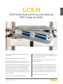
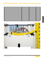
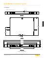
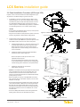
1
Bulkhead-Style Optical Panels
Telect LCX Series
The network’s ubiquitous solution for deploying, protecting, and managing fiber.
For every network. For every nation.
LCX Series
everything guide
Overview
Datasheets
Cross-Reference Guide/
Order Guide
Installation Guide
about us :: about you
It’s time to generate more revenue. It’s time to rev your network velocity.
It’s time to simplify your network.
It’s clear. You need to connect, power, protect, and manage your revenue stream. You need intuitive system integration, fast lead times, and
unyielding reliability. You need a global network manufacturer who dominates demanding network requirements, and a team who understands
network trajectory and gets the whole picture, from the central office to the edge. You need a futuristic manufacturer today.
It’s not about anybody else. It’s about you.
It’s about buying you-centric equipment. It’s about using a network manufacturer that grasps your vision for the future and knows how to build
it, backed by a history of network innovation; a deep portfolio of integrated, cross-sector network equipment; and the best team on earth.
At Telect, you get more than the crucial equipment you need to build and maintain your network. You get solutions for network dominance.
Telect :: We simplify networks.
www.telect.com
Contact Telect for more information and for assistance with configuring a solution.
[email protected] :: 1.509.926.6000
Bulkhead-style patching and splicing.
With hinge benefits.
Meet Telect’s ubiquitous patch and splice panel. With
hinge benefits.
Telect also escalated bend radius management and
laser protection by engineering LGX®-compatible, angled
adapter plates into the LCX-H.
Managing and protecting fiber just got simpler.
Telect designed the LCX-H to be the industry’s model
bulkhead-style panel.
With the product launch of LCX-H, a total front-access,
bulkhead-style panel, Telect blazes ahead in fiber-optic
equipment innovation with a reversible hinge. From now
on, you don’t have to decide the destiny of your hinged
swing before it leaves the factory. Now, when you’re
maneuvering tight network spaces in central offices,
switches, or data centers, you can get total front access
and the on-site freedom to install the bulkhead to swing
either left or right.
From the hinged bulkhead; to the adapter plates; to the
front-to-back, pass-through cables within the chassis; to
superior cable management; to thorough fiber protection;
to competitive pricing; to a cutthroat lead-time of 24-48
hours— Telect’s LCX-H panel is the clear solution for
simple fiber protection and management in all networks.
You’re going to love hinge benefits.
One more step toward total network flexibility.
© Telect, Inc., All Rights Reserved, 126254-6 A0
1.509.926.6000 :: telect.com
3
overview
LCX-H
LCX-H datasheet
Benefits
• Flexible hinged bulkhead for right or left exits
• Cutouts for fiber pass-through within the chassis
datasheet
• Premium-grade Senko adapters
• A LGX® compatible system
• Angled adapter plates for any LGX® compatible system
Applications
• Central office
• Data center
• Optical distribution frame
Specifications
• Fiber distribution within equipment room
Dimensions and Weights
• Total front access
All Panels
1 RU patch or splice panel
Capacities/Capabilities/Suitability
• LCX-H panels are available for universal 19-in., 23-in., and
ETSI racks.
3.5" H (89 mm), 6 lbs (2.72 kg)
3 RU patch or splice panel
5.25" H (133 mm), 7 lbs (3.18 kg)
2 RU combination panel
• Standard-size 6, 8, 12, or 24 adapters per patch plate for on-site
patch panel adaptation of empty panels.
• Standard-size Wavelength Division Multiplexing (WDM) and
splitter modules can be used along with adapter packs for
added flexibility.
1.75" H (44 mm), 5 lbs (2.27 kg)
2 RU patch or splice panel
4 RU patch or splice panel
• 12-144 (LC) termination capacities per panel (1 RU through
4 RU) using site-installed patch plates. Up to 144 terminations
per panel with factory-installed discrete adapters.
17" W (432 mm), 11" D (280 mm)
7" H (178 mm), 8 lbs (3.63 kg)
3.5" H (89 mm), 10 lbs (4.54 kg)
4 RU combination panel
7" H (282 mm), 12 lbs (5.44 kg)
6 RU combination panel
10.5" H (267 mm), 14 lbs (6.35 kg)
8 RU combination panel
14" H (356 mm), 16 lbs (7.26 kg)
Mechanical
• All LCX Patch/Splice Panels are fully compatible with standard
LGX® style panels for IFC entrance, splicing, and network
patching architecture.
Enclosure type
• 2 RU through 4 RU models include slip-on, split arcs for patch
cord entrance; optional cable management kits are available to
suit operating company preferences.
Connector type
Capacity
Rack-mount panel
12, 24, 48, 72, 96, 144 (LC only)
ports based on configuration
LC, LC quad, SC, SC duplex, ST, FC
or MPO based on configuration
Material
Aluminum
Panel mounting
19" or 23"
Environmental
Humidity
Temperature
0 to 90%, non-condensing
-5 to 55 deg. C
Compliance
Agency compliance
Mounting
NEBS, ETSI, Zone 4 Seismic
reliability
19-in. or 23-in. with ETSI, EIA, or
WECO spacing
Angled Adapter (also available in black)
© Telect, Inc., All Rights Reserved, 126254-6 A0
1.509.926.6000 :: telect.com
4
Protect and manage fiber with confidence.
In every network. In every nation.
Deploy fiber with confidence.
Brains :: Telect engineers get cerebral about fiber
protection. LCX simplifies patching, splicing, and splitting,
from fiber bend radius protection; to standard 19", 23",
or ETSI footprints; to LGX®-compatibility; to NEBS
certification; to superior integrated cable management; to
densities from 12 to 144 terminations; to hinged bulkheadstyle panel configurations and adapter plates. LCX panels
fit the network.
Telect’s LCX bulkhead-style panels are fundamental for
your fiber network. As the ubiquitous fiber management
solution for cost-effective patching, splicing, and splitting
across all networks, LCX bulkhead-style panels protect
fiber and build sustainability into your infrastructure.
Everybody’s talking about the LCX.
Find it all in the LCX series.
Potential :: LCX’s minimal footprint—from 1 to 4 RUs—
leaves plenty of space for other equipment. The NEBS
Level 3 certification ensures that you’re investing in
network sustainability, and the modularity enables you to
build future revenue opportunities into your network.
Money-smarts :: From CAPEX to OPEX, LCX helps you
maintain a green bottom line.
The good looks and charm are bonuses. But we think
you’ll appreciate them.
Money-smarts. Brains. Potential. Good looks. Even some
charm.
© Telect, Inc., All Rights Reserved, 126254-6 A0
1.509.926.6000 :: telect.com
5
overview
LCX Series
LCX Series datasheet
Benefits
Telect’s LCX Splice/Patch Panels are ideal for central office, headend and wiring centers. Benefits include:
datasheet
• Compliance in design
• Bend radius management
• Flammability safety
• Structural reliability
• Lightweight construction
• Standard footprint
• Simple installation
• Scalability to help manage costs
Specifications
• Pre-loaded configurations to accelerate deployment
Dimensions and Weights
Applications
All Panels
• CATV
1 RU patch or splice panel
• MTSO
• Outside plant
• Central office
• Optical distribution/cross-connect
Capacities/Capabilities/Suitability
• LCX panels are available for universal 19-in., 23-in., and
ETSI racks.
• 12-144 (LC) termination capacities per panel (1 RU through
4 RU) using site-installed patch plates. Up to 144 terminations
per panel with factory-installed discrete adapters. 144 for SC
duplex and LC quad provides 288.
17" W (432 mm), 11" D (280 mm)
1.75" H (44 mm), 5 lbs (2.27 kg)
2 RU patch or splice panel
3.5" H (89 mm), 6 lbs (2.72 kg)
3 RU patch or splice panel
5.25" H (133 mm), 7 lbs (3.18 kg)
4 RU patch or splice panel
7" H (178 mm), 8 lbs (3.63 kg)
2 RU combination panel
3.5" H (89 mm), 10 lbs (4.54 kg)
4 RU combination panel
7" H (282 mm), 12 lbs (5.44 kg)
6 RU combination panel
10.5" H (267 mm), 14 lbs (6.35 kg)
8 RU combination panel
14" H (356 mm), 16 lbs (7.26 kg)
Mechanical
Enclosure type
Capacity
• Standard-size 6, 8, 12 or 24 adapters per patch plate for on-site
patch panel adaptation of empty panels.
Connector type
• Standard-size Wavelength Division Multiplexing (WDM) and
splitter modules can be used along with adapter packs for
added flexibility.
• All LCX Patch/Splice Panels are fully compatible with standard
LGX® style panels for IFC entrance, splicing, and network
patching architecture.
Rack-mount panel
12, 24, 48, 72, 96, 144 (LC only)
ports based on configuration
LC, LC quad, SC, SC duplex, ST, FC
or MPO based on configuration
Material
Aluminum
Panel mounting
19" or 23"
Environmental
• 2 RU through 4 RU models include slip-on, split arcs for patch
cord entrance; optional cable management kits are available to
suit operating company preferences.
Humidity
Temperature
0 to 90%, non-condensing
-5 to 55 deg. C
Compliance
Agency compliance
Mounting
© Telect, Inc., All Rights Reserved, 126254-6 A0
1.509.926.6000 :: telect.com
6
NEBS, ETSI, Zone 4 Seismic
reliability
19-in. or 23-in. with ETSI, EIA, or
WECO spacing
LCX-H competitive cross-reference/ordering guide
LCX-H Chassis Only
Description
Competitor Part Number
Telect Part Number
LCX Hinged Splice/Patch Chassis 24 Fiber, 4 RU
FL2-24TS525
LCX-HC4 RU
LCX Hinged Splice/Patch Chassis 48 Fiber, 6 RU
FL2-48TS875
LCX-HC6 RU
LCX Hinged Splice/Patch Chassis 72/96 Fiber, 8 RU
FL2-72TS140
LCX-HC8 RU
LCX Hinged Patch Chassis 24 Fiber, 2 RU
FL2-24RPNL
LCX-H2 RU
LCX Hinged Patch Chassis 48 Fiber, 3 RU
FL2-48RPNL
LCX-H3 RU
LCX Hinged Patch Chassis 72/96 Fiber, 4 RU
FL2-72RPNL
LCX-H4 RU
Quantity
LCX-S2 RU
LCX Splice Chassis 24 Fiber, 2 RU
FL2-48SPNL
LCX-S3 RU
LCX Splice Chassis 72/96 Fiber, 4 RU
FL2-96SPNL
LCX-S4 RU
LCX Hinged Splice/Patch Chassis 48 Fiber, 6 RU
LCX-HC6 RU-BLK
LCX Hinged Splice/Patch Chassis 72/96 Fiber, 8 RU
LCX-HC8 RU-BLK
LCX Hinged Patch Chassis 24 Fiber, 2 RU
LCX-H2 RU-BLK
LCX Hinged Patch Chassis 48 Fiber, 3 RU
LCX-H3 RU-BLK
LCX Hinged Patch Chassis 72/96 Fiber, 4 RU
LCX-H4 RU-BLK
LCX Splice Tray - 24 Fiber RoHs
LCX-S-HSF
cross-reference
order guide
LCX Splice Chassis 48 Fiber, 3 RU
LCX-H Configured Patch Only Panels :: For black add -BLK
Description
Competitor Part Number
Telect Part Number
LCX-HP241D
LCX-Hinged 24 Patch, FC/APC, 19/23" Std 2 RU
LCX-Hinged 24 Patch, FC/UPC, 19/23" Std. 2 RU
FL2-R220024A0-0A00
LCX-HP241F
LCX-Hinged 24 Patch, LC/APC, 19/23" Std. 2 RU
FL2-R2B0024A0-0A00
LCX-HP241G
LCX-Hinged 24 Patch, LC/UPC, 19/23" Std. 2 RU
FL2-R280024A0-0A00
LCX-HP241L
LCX-Hinged 24 Patch, LC Multimode, 19/23" Std. 2 RU
FL2-R260024A0-0A00
LCX-HP241L-MM
LCX-Hinged 24 Patch, SC/APC, 19/23" Std. 2 RU
FL2-R2J0024A0-0A00
LCX-HP241N
LCX-Hinged 24 Patch, SC/UPC, 19/23" Std. 2 RU
FL2-R270024A0-0A00
LCX-HP241S
LCX-Hinged 24 Patch, SC Multimode, 19/23" Std. 2 RU
FL2-R290024A0-0A00
LCX-HP241S-MM
LCX-Hinged 24 Patch, ST/UPC, 19/23" Std. 2 RU
LCX-HP241T
LCX-Hinged 48 Patch, FC/APC, 19/23" Std. 3 RU
LCX-HP481D
LCX-Hinged 48 Patch, FC/UPC, 19/23" Std. 3 RU
FL2-R420048A0-0A00
LCX-HP481F
LCX-Hinged 48 Patch, LC/APC, 19/23" Std. 2 RU
FL2-R4B0048A0-0A00
LCX-HP481G
LCX-Hinged 48 Patch, LC/UPC, 19/23" Std. 2 RU
FL2-R480048A0-0A00
LCX-HP481L
LCX-Hinged 48 Patch, LC Multimode, 19/23" Std. 2 RU
FL2-R460048A0-0A00
LCX-HP481L-MM
LCX-Hinged 48 Patch, SC/APC, 19/23" Std. 3 RU
FL2-R4J0048A0-0A00
LCX-HP481N
LCX-Hinged 48 Patch, SC/UPC, 19/23" Std. 3 RU
FL2-R470048A0-0A00
LCX-HP481S
LCX-Hinged 48 Patch, SC Multimode, 19/23" Std. 3 RU
FL2-R490048A0-0A00
LCX-HP481S-MM
LCX-Hinged 48 Patch, ST/UPC, 19/23" Std. 3 RU
LCX-HP481T
LCX-Hinged 72 Patch, FC/APC, 19/23" Std. 4 RU
LCX-HP721D
LCX-Hinged 72 Patch, FC/UPC, 19/23" Std. 4 RU
FL2-R720072A0-0A00
LCX-HP721F
LCX-Hinged 72 Patch, LC/APC, 19/23" Std. 3 RU
FL2-R7B0072A0-0A00
LCX-HP721G
LCX-Hinged 72 Patch, LC/UPC, 19/23" Std. 3 RU
FL2-R780072A0-0A00
LCX-HP721L
LCX-Hinged 72 Patch, LC Multimode, 19/23" Std. 3 RU
FL2-R760072A0-0A00
LCX-HP721L-MM
LCX-Hinged 72 Patch, SC/APC, 19/23" Std. 4 RU
FL2-R7J0072A0-0A00
LCX-HP721N
LCX-Hinged 72 Patch, SC/UPC, 19/23" Std. 4 RU
FL2-R770072A0-0A00
LCX-HP721S
LCX-Hinged 72 Patch, SC Multimode, 19/23" Std. 4 RU
FL2-R790072A0-0A00
LCX-HP721S-MM
LCX-HP721T
LCX-Hinged 72 Patch, ST/UPC, 19/23" Std. 4 RU
LCX-Hinged 96 Patch, LC/APC, 19/23" Std. 3 RU
FL2-R9B0096A0-0A00
LCX-HP961G
LCX-Hinged 96 Patch, LC/UPC, 19/23" Std. 3 RU
FL2-R980096A0-0A00
LCX-HP961L
© Telect, Inc., All Rights Reserved, 126254-6 A0
1.509.926.6000 :: telect.com
7
Quantity
LCX-H competitive cross-reference/ordering guide
LCX-H Configured Patch/Splice Combo Panels
Description
Competitor Part Number
cross-reference
order guide
Telect Part Number
Quantity
LCX-HC241D
LCX-Hinged 24 Patch/Splice, FC/APC, 19/23" Std. 4 RU
LCX-Hinged 24 Patch/Splice, FC/UPC, 19/23" Std. 4 RU
FL2-C220024P2-2A00
LCX-HC241F
LCX-Hinged 24 Patch/Splice, LC/APC, 19/23" Std. 3 RU
FL2-C2B0024P2-2A00
LCX-HC241G
LCX-Hinged 24 Patch/Splice, LC/UPC, 19/23" Std. 3 RU
FL2-C260024P2-2A00
LCX-HC241L
LCX-Hinged 24 Patch/Splice, LC Multimode,19/23" Std. 3 RU
FL2-C280024P2-2A00
LCX-HC241L-MM
LCX-Hinged 24 Patch/Splice, SC/APC, 19/23" Std. 4 RU
FL2-C2J0024P2-2A00
LCX-HC241N
LCX-Hinged 24 Patch/Splice, SC/UPC, 19/23" Std. 4 RU
FL2-C270024P2-2A00
LCX-HC241S
LCX-Hinged 24 Patch/Splice, SC Multimode,19/23" Std. 4 RU
FL2-C290024P2-2A00
LCX-HC241S-MM
LCX-HC241T
LCX-Hinged 24 Patch/Splice, ST/UPC, 19/23" Std. 4 RU
LCX-HC481D
LCX-Hinged 48 Patch/Splice, FC/APC, 19/23" Std. 6 RU
LCX-Hinged 48 Patch/Splice, FC/UPC, 19/23" Std. 6 RU
FL2-C420048P2-4A00
LCX-HC481F
LCX-Hinged 48 Patch/Splice, LC/APC, 19/23" Std. 5 RU
FL2-C4B0048P2-4A00
LCX-HC481G
LCX-Hinged 48 Patch/Splice, LC/UPC, 19/23" Std. 5 RU
FL2-C4B0048P2-4A00
LCX-HC481L
LCX-Hinged 48 Patch/Splice, LC Multimode,19/23" Std. 5 RU
FL2-C480048P2-4A00
LCX-HC481L-MM
LCX-Hinged 48 Patch/Splice, SC/APC, 19/23" Std. 6 RU
FL2-C4J0048P2-4A00
LCX-HC481N
LCX-Hinged 48 Patch/Splice, SC/UPC, 19/23" Std. 6 RU
FL2-C470048P2-4A00
LCX-HC481S
LCX-Hinged 48 Patch/Splice, SC Multimode, 19/23" Std. 6 RU
FL2-C490048P2-4A00
LCX-HC481S-MM
LCX-HC481T
LCX-Hinged 48 Patch/Splice, ST/UPC, 19/23" Std. 6 RU
LCX-Hinged 72 Patch/Splice, FC/APC,19/23" Std. 8 RU
FL2-C720072P2-6A00
LCX-HC721D
LCX-Hinged 72 Patch/Splice, FC/UPC, 19/23" Std. 8 RU
FL2-C7B0072P2-6A00
LCX-HC721F
LCX-Hinged 72 Patch/Splice, LC/APC, 19/23" Std. 7 RU
FL2-C760072P2-6A00
LCX-HC721G
LCX-Hinged 72 Patch/Splice, LC/UPC, 19/23" Std. 7 RU
FL2-C780072P2-6A00
LCX-HC721L
LCX-Hinged 72 Patch/Splice, LC Multimode, 19/23" Std. 7 RU
FL2-C7J0072P2-6A00
LCX-HC721L-MM
LCX-Hinged 72 Patch/Splice, SC/APC, 19/23" Std. 8 RU
FL2-C770072P2-6A00
LCX-HC721N
LCX-Hinged 72 Patch/Splice, SC/UPC, 19/23" Std. 8 RU
FL2-C790072P2-6A00
LCX-HC721S
LCX-HC721S-MM
LCX-Hinged 72 Patch/Splice, SC Multimode, 19/23" Std. 8 RU
LCX-Hinged 96 Patch/Splice, LC/APC, 19/23" Std. 7 RU
FL2-C960096P2-8A00
LCX-HC961G
LCX-Hinged 96 Patch/Splice, LC/UPC, 19/23" Std. 7 RU
FL2-C980096P2-8A00
LCX-HC961L
LCX-Hinged 96 Patch/Splice, LC Multimode, 19/23" Std. 7 RU
FL2-C9J0096P2-8A00
LCX-HC961L-MM
LCX-H Angled Adapter Plates (for black add -V and -BLKV)
Description
Competitor Part Number
Telect Part Number
Patch Plate, Blank
FL2-6PBLNK
055-0000-9000
Angled Patch Plate, 6-Port, FC/UPC
FL2-6PSMFC
055-0000-2A10
Angled Patch Plate, 6-Port, FC/APC
No Direct Cross
055-0000-2A70
Angled Patch Plate, 8-Port, FC/UPC
No Direct Cross
055-0000-2A80
Angled Patch Plate, 8-Port, FC/APC
No Direct Cross
055-0000-2A90
Angled Patch Plate, 6-Port, ST/UPC
No Direct Cross
055-0000-3A10
Angled Patch Plate, 8-Port, ST/UPC
No Direct Cross
055-0000-3A80
Angled Patch Plate, 12-Port, LC/UPC
FL2-6PSMLC
055-0000-5A10
Angled Patch Plate, 12-Port, LC Multimode
FL2-6PMMLC
055-0000-5A12
Angled Patch Plate, 12-Port, LC/APC
FL2-6PSMALC
055-0000-5A90
Angled Patch Plate, 16-Port, LC/UPC
No Direct Cross
055-0000-5A11
Angled Patch Plate, 16-Port, LC Multimode
No Direct Cross
055-0000-5A13
Angled Patch Plate, 16-Port, LC/APC
No Direct Cross
055-0000-5A91
© Telect, Inc., All Rights Reserved, 126254-6 A0
1.509.926.6000 :: telect.com
8
Quanitity
LCX-H competitive cross-reference/ordering guide
No Direct Cross
055-0000-5A210
Angled Patch Plate, 24-Port, LC/APC
No Direct Cross
055-0000-5A290
Angled Patch Plate, 24-Port, LC/MM
No Direct Cross
055-0000-2A412
Angled Patch Plate, 6-Port, SC/UPC
FL2-6PSMSC
055-0000-6A10
Angled Patch Plate, 6-Port, SC Multimode
FL2-6PMMSC
055-0000-6A20
Angled Patch Plate, 6-Port, SC/APC
FL2-6PSMASC
055-0000-6A70
Angled Patch Plate, 8-Port, SC/UPC
No Direct Cross
055-0000-6A80
Angled Patch Plate, 8-Port, SC Multimode
No Direct Cross
055-0000-6A82
Angled Patch Plate, 8-Port, SC/APC
No Direct Cross
055-0000-6A90
Angled Patch Plate, 12-Port, SC/UPC
No Direct Cross
055-0000-6A210
Angled Patch Plate, 12-Port, SC/APC
No Direct Cross
055-0000-6A270
Angled Patch Plate, 12-Port, SC/MM
No Direct Cross
055-0000-6A220
Angled Patch Plate, 6-Port, MTP/MPO
No Direct Cross
055-0000-MTA06
Angled Patch Plate, 8-Port, MTP/MPO
No Direct Cross
055-0000-MTA08
© Telect, Inc., All Rights Reserved, 126254-6 A0
1.509.926.6000 :: telect.com
9
cross-reference
order guide
Angled Patch Plate, 24-Port, LC/UPC
LCX-H competitive cross-reference/ordering guide
cross-reference
order guide
LCX Series Chassis Only
Description
Competitor Part Number
Telect Part Number
LCX Patch/Splice Chassis 12-Fiber, 2 RU
No Direct Cross
LCX-C2RU
LCX Patch/Splice Chassis 24-Fiber, 4 RU
No Direct Cross
LCX-C4RU
LCX Patch/Splice Chassis 48-Fiber, 6 RU
No Direct Cross
LCX-C6RU
LCX Patch/Splice Chassis 72/96-Fiber, 8 RU
No Direct Cross
LCX-C8RU
LCX Splice Chassis 12-Fiber, 1 RU
LSX-100000
LCX-M1RU
LCX Splice Chassis 24-Fiber, 2 RU
LSX-200000
LCX-M2RU
LCX Splice Chassis 48-Fiber, 3 RU
LSX-300000
LCX-M3RU
LCX Splice Chassis 72/96/144-Fiber, 4 RU
LSX-600000
LCX-M4RU
LCX Splice Chassis 12-Fiber, 1 RU
LSX-SPLCA01
LCX-S1RU
LCX Splice Chassis 24-Fiber, 2 RU
No Direct Cross
LCX-S2RU
LCX Splice Chassis 48-Fiber, 3 RU
No Direct Cross
LCX-S3RU
LCX Splice Chassis 72/96-Fiber, 4 RU
No Direct Cross
LCX-S4RU
LCX Splice Chassis 144-Fiber, 4 RU
LSX-SPLCA06
LCX-S141
LCX Splice Tray - 24-Fiber, ROHS
No Direct Cross
LCX-S-HSF
Description
Competitor Part Number
Part Number
LCX-12 Patch, FC/APC, 19/23" Std. 1 RU
No Direct Cross
LCX-P121D
LCX-12 Patch, FC/UPC, 19/23" Std. 1 RU
LSX-120000-12
LCX-P121F
LCX-12 Patch, LC/APC,19/23" Std. 1 RU
No Direct Cross
LCX-P121G
LCX-12 Patch, LC/UPC,19/23" Std. 1 RU
LSX-1K0000-12
LCX-P121L
LCX-12 Patch, LC Multimode, 19/23" Std. 1 RU
No Direct Cross
LCX-P121L-MM
LCX-12 Patch, SC/APC, 19/23" Std. 1 RU
LSX-1L0000-12
LCX-P121N
LCX-12 Patch, SC/UPC, 19/23" Std. 1 RU
LSX-170000-12
LCX-P121S
LCX-12 Patch, SC Multimode, 19/23" Std. 1 RU
LSX-1T0000-12
LCX-P121S-MM
LCX-12 Patch, ST/UPC, 19/23" Std. 1 RU
No Direct Cross
LCX-P121T
LCX-24 Patch, FC/APC, 19/23" Std. 2 RU
No Direct Cross
LCX-P241D
LCX-24 Patch, FC/UPC, 19/23" Std. 2 RU
LSX-120000
LCX-P241F
LCX-24 Patch, LC/APC,19/23" Std. 1 RU
LSX-1M0000
LCX-P241G
LCX-24 Patch, LC/UPC,19/23" Std. 1 RU
LSX-1K0000
LCX-P241L
LCX-24 Patch, LC Multimode, 19/23" Std. 1 RU
LSX-1C0000
LCX-P241L-MM
LCX-24 Patch, SC/APC,19/23" Std. 2 RU
LSC-20PL
LCX-P241N
LCX-24 Patch, SC/UPC,19/23" Std. 2 RU
LSX-24P7
LCX-P241S
LCX-24 Patch, SC Multimode, 19/23" Std. 2 RU
LSX-24P9
LCX-P241S-MM
LCX-24 Patch, ST/UPC, 19/23" Std. 2 RU
No Direct Cross
LCX-P241T
LCX-48 Patch, FC/APC, 19/23" Std. 3 RU
No Direct Cross
LCX-P481D
LCX-48 Patch, FC/UPC, 19/23" Std. 3 RU
LSX-220000
LCX-P481F
LCX-48 Patch, LC/APC, 19/23" Std. 2 RU
LSX-2M0000
LCX-P481G
LCX-48 Patch, LC/UPC, 19/23" Std. 2 RU
LSX-2K0000
LCX-P481L
LCX-48 Patch, LC Multimode, 19/23" Std. 2 RU
LSX-2C0000
LCX-P481L-MM
LCX-48 Patch, SC/APC, 19/23" Std. 3 RU
LSX-2L0000
LCX-P481N
LCX-48 Patch, SC/UPC, 19/23" Std. 3 RU
LSX-270000
LCX-P481S
LCX-48 Patch, SC Multimode, 19/23" Std. 3 RU
LSX-2T0000
LCX-P481S-MM
LCX-48 Patch, ST/UPC, 19/23" Std. 3 RU
No Direct Cross
LCX-P481T
LCX-72 Patch, FC/APC, 19/23" Std. 4 RU
No Direct Cross
LCX-P721D
Quantity
Configured LCX Patch Only Panels
© Telect, Inc., All Rights Reserved, 126254-6 A0
1.509.926.6000 :: telect.com
10
Quantity
LCX-H competitive cross-reference/ordering guide
LSX-620000
LCX-P721F
LCX-72 Patch, LC/APC, 19/23" Std. 3 RU
LSX-6M0000
LCX-P721G
LCX-72 Patch, LC/UPC, 19/23" Std. 3 RU
LSX-6K0000
LCX-P721L
LCX-72 Patch, LC Multimode, 19/23" Std. 3 RU
LSX-6C0000
LCX-P721L-MM
LCX-72 Patch, SC/APC, 19/23" Std. 4 RU
LSX-6L0000
LCX-P721N
LCX-72 Patch, SC/UPC, 19/23" Std. 4 RU
LSX-670000
LCX-P721S
LCX-72 Patch, SC Multimode, 19/23" Std. 4 RU
LSX-6T0000
LCX-P721S-MM
LCX-72 Patch, ST/UPC, 19/23" Std. 4 RU
No Direct Cross
LCX-P721T
LCX-96 Patch, FC/APC, 19/23" Std. 4 RU
No Direct Cross
LCX-P961D
LCX-96 Patch, FC/UPC, 19/23" Std. 4 RU
LSX-720000
LCX-P961F
LCX-96 Patch, LC/APC, 19/23" Std. 3 RU
LSX-7M0000
LCX-P961G
LCX-96 Patch, LC/UPC, 19/23" Std. 3 RU
LSX-7K0000
LCX-P961L
LCX-96 Patch, LC Multimode, 19/23" Std. 3 RU
LSX-7C0000
LCX-P961L-MM
LCX-96 Patch, SC/APC, 19/23" Std. 4 RU
LSX-7L0000
LCX-P961N
LCX-96 Patch, SC/UPC, 19/23" Std. 4 RU
LSX-770000
LCX-P961S
LCX-96 Patch, SC Multimode, 19/23" Std. 4 RU
LSX-7T0000
LCX-P961S-MM
LCX-96 Patch, ST/UPC, 19/23" Std. 4 RU
No Direct Cross
LCX-P961T
LCX-144 Patch, FC/APC, 19/23" Std. 4 RU
No Direct Cross
LCX-P141D
LCX-144 Patch, FC/UPC, 19/23" Std. 4 RU
LSX-T20000
LCX-P141F
LCX-144 Patch, LC/APC, 19/23" Std. 4 RU
LSX-TM0000
LCX-P141G
LCX-144 Patch, LC/UPC, 19/23" Std. 4 RU
LSX-TK0000
LCX-P141L
LCX-144 Patch, LC Multimode, 19/23" Std. 4 RU
LSX-TC0000
LCX-P141L-MM
LCX-144 Patch, SC/APC, 19/23" Std. 4 RU
LSX-TL0000
LCX-P141N
LCX-144 Patch, SC/UPC, 19/23" Std. 4 RU
LSX-T70000
LCX-P141S
LCX-144 Patch, SC Multimode, 19/23" Std. 4 RU
LSX-TT0000
LCX-P141S-MM
LCX-144 Patch, ST/UPC, 19/23" Std. 4 RU
No Direct Cross
LCX-P141T
cross-reference
order guide
LCX-72 Patch, FC/UPC, 19/23" Std. 4 RU
Configured LCX Splice Only Panels
Description
Competitor Part Number
Part Number
LCX-24 Fiber/Splice 19/23" Std. 2 RU
No Direct Cross
LCX-S241
LCX-48 Fiber/Splice 19/23" Std. 3 RU
No Direct Cross
LCX-S481
LCX-96 Fiber/Splice 19/23" Std. 4 RU
No Direct Cross
LCX-S961
© Telect, Inc., All Rights Reserved, 126254-6 A0
1.509.926.6000 :: telect.com
11
Quantity
LCX cross-reference/ordering guide
cross-reference
order guide
Configured LCX Combo Patch & Splice Panels
Description
Competitor Part Number
Part Number
LCX-12 Splice/Patch, FC/APC, 19/23" Std. 2 RU
No Direct Cross
LCX-C121D
LCX-12 Splice/Patch, FC/UPC, 19/23" Std. 2 RU
LSX-121012-A-SPL
LCX-C121F
LCX-12 Splice/Patch, LC/APC, 19/23" Std. 2 RU
No Direct Cross
LCX-C121G
LCX-12 Splice/Patch, LC/UPC, 19/23" Std. 2 RU
No Direct Cross
LCX-C121L
LCX-12 Splice/Patch, LC Multimode, 19/23" Std. 2 RU
No Direct Cross
LCX-C121L-MM
LCX-12 Splice/Patch, SC/APC, 19/23" Std. 2 RU
LSX-1L1012-A-SPL
LCX-C121N
LCX-12 Splice/Patch, SC/UPC, 19/23" Std. 2 RU
LSX-171012-A-SPL
LCX-C121S
LCX-12 Splice/Patch, SC Multimode, 19/23" Std. 2 RU
LSX-1T1012-A-SPL
LCX-C121S-MM
LCX-12 Splice/Patch, ST/UPC, 19/23" Std. 2 RU
No Direct Cross
LCX-C121T
LCX-24 Splice/Patch, FC/APC, 19/23" Std. 4 RU
No Direct Cross
LCX-C241D
LCX-24 Splice/Patch, FC/UPC, 19/23" Std. 4 RU
LSX-121022-A-SPL
LCX-C241F
LCX-24 Splice/Patch, LC/APC, 19/23" Std. 3 RU
No Direct Cross
LCX-C241G
LCX-24 Splice/Patch, LC/UPC, 19/23" Std. 3 RU
No Direct Cross
LCX-C241L
LCX-24 Splice/Patch, LC Multimode, 19/23" Std. 3 RU
No Direct Cross
LCX-C241L-MM
LCX-24 Splice/Patch, SC/APC, 19/23" Std. 4 RU
LSX-1L1022-A-SPL
LCX-C241N
LCX-24 Splice/Patch, SC/UPC, 19/23" Std. 4 RU
LSX-171022-A-SPL
LCX-C241S
LCX-24 Splice/Patch, SC Multimode, 19/23" Std. 4 RU
LSX-1T1022-A-SPL
LCX-C241S-MM
LCX-24 Splice/Patch, ST/UPC, 19/23" Std. 4 RU
No Direct Cross
LCX-C241T
LCX-48 Splice/Patch, FC/APC, 19/23" Std. 6 RU
No Direct Cross
LCX-C481D
LCX-48 Splice/Patch, FC/UPC, 19/23" Std. 6 RU
LSX-321042-A-SPL
LCX-C481F
LCX-48 Splice/Patch, LC/APC, 19/23" Std. 5 RU
No Direct Cross
LCX-C481G
LCX-48 Splice/Patch, LC/UPC, 19/23" Std., 5 RU
No Direct Cross
LCX-C481L
LCX-48 Splice/Patch, LC Multimode, 19/23" Std. 5 RU
No Direct Cross
LCX-C481L-MM
LCX-48 Splice/Patch, SC/APC, 19/23" Std. 6 RU
LSX-3L1042-A-SPL
LCX-C481N
LCX-48 Splice/Patch, SC/UPC, 19/23" Std. 6 RU
LSX-371042-A-SPL
LCX-C481S
LCX-48 Splice/Patch, SC Multimode, 19/23" Std. 6 RU
LSX-3T1042-A-SPL
LCX-C481S-MM
LCX-48 Splice/Patch, SC/UPC, 19/23" Std. 6 RU 3M PIGTAIL
No Direct Cross
LCX-C481S-3M
LCX-48 Splice/Patch, ST/UPC, 19/23" Std. 6 RU
No Direct Cross
LCX-C481T
LCX-72 Splice/Patch, FC/APC, 19/23" Std. 8 RU
No Direct Cross
LCX-C721D
LCX-72 Splice/Patch, FC/UPC, 19/23" Std. 8 RU
LSX-621062-A-SPL
LCX-C721F
LCX-72 Splice/Patch, LC/APC, 19/23" Std. 7 RU
No Direct Cross
LCX-C721G
LCX-72 Splice/Patch, LC/UPC, 19/23" Std., 7 RU
No Direct Cross
LCX-C721L
LCX-72 Splice/Patch, LC Multimode, 19/23" Std. 7 RU
No Direct Cross
LCX-C721L-MM
LCX-72 Splice/Patch, SC/APC, 19/23" Std. 8 RU
LSX-6L1062-A-SPL
LCX-C721N
LCX-72 Splice/Patch, SC/UPC, 19/23" Std. 8 RU
LSX-671062-A-SPL
LCX-C721S
LCX-72 Splice/Patch, SC Multimode, 19/23" Std. 8 RU
LSX-6T1062-A-SPL
LCX-C721S-MM
LCX-72 Splice/Patch, ST/UPC, 19/23" Std. 8 RU
No Direct Cross
LCX-C721T
LCX-96 Splice/Patch, FC/APC, 19/23" Std. 8 RU
No Direct Cross
LCX-C961D
LCX-96 Splice/Patch, FC/UPC, 19/23" Std. 8 RU
LSX-721082-A-SPL
LCX-C961F
LCX-96 Splice/Patch, LC/APC, 19/23" Std. 7 RU
No Direct Cross
LCX-C961G
LCX-96 Splice/Patch, LC/UPC, 19/23" Std., 7 RU
No Direct Cross
LCX-C961L
LCX-96 Splice/Patch, LC Multimode, 19/23" Std. 7 RU
No Direct Cross
LCX-C961L-MM
LCX-96 Splice/Patch, SC/APC, 19/23" Std. 8 RU
LSX-7L1082-A-SPL
LCX-C961N
LCX-96 Splice/Patch, SC/UPC, 19/23" Std. 8 RU
LSX-771082-A-SPL
LCX-C961S
LCX-96 Splice/Patch, SC Multimode, 19/23" Std. 8 RU
LSX-7T1082-A-SPL
LCX-C961S-MM
© Telect, Inc., All Rights Reserved, 126254-6 A0
1.509.926.6000 :: telect.com
12
Quantity
LCX cross-reference/ordering guide
No Direct Cross
LCX-C961T
LCX-144 Splice/Patch, FC/APC, 19/23" Std. 8 RU
No Direct Cross
LCX-C141D
LCX-144 Splice/Patch, C/UPC, 19/23" Std. 8 RU
LSX-T21122-A-SPL
LCX-C141F
LCX-144 Splice/Patch, LC/APC,19/23" Std. 8 RU
LSX-TM1122-A-SPL
LCX-C141G
LCX-144 Splice/Patch, LC/UPC,19/23" Std. 8 RU
LSX-TK1122-A-SPL
LCX-C141L
LCX-144 Splice/Patch, LC Multimode, 19/23" Std. 8RU
LSX-TC1122-A-SPL
LCX-C141L-MM
LCX-144 Splice/Patch, SC/APC, 19/23" Std. 8 RU
LSX-TL1122-A-SPL
LCX-C141N
LCX-144 Splice/Patch, SC/UPC, 19/23" Std. 8 RU
LSX-T71122-A-SPL
LCX-C141S
LCX-144 Splice/Patch, SC Multimode, 19/23" Std. 8 RU
LSX-TT1122-A-SPL
LCX-C141S-MM
LCX-144 Splice/Patch, ST/UPC, 19/23" Std. 8 RU
No Direct Cross
LCX-C141T
LCX Standard Adapter Plates
Description
Competitor Part Number
Part Number
Patch Plate, 6-Port, FC/UPC
LSX-6PSMFC
055-0000-2010
Patch Plate, 6-Port, FC/APC
No Direct Cross
055-0000-2070
Patch Plate, 8-Port, FC/UPC
LSX-8P2
055-0000-2080
Patch Plate, 8-Port, FC/APC
LSX-8PSMAFC
055-0000-2090
Patch Plate, 6-Port, ST/UPC
LSX-6PSMST
055-0000-3010
Patch Plate, 6-Port, ST Multimode
LSX-6PMMST
055-0000-3020
Patch Plate, 8-Port, ST/UPC
No Direct Cross
055-0000-3080
Patch Plate, 12-Port, LC/UPC
LSX-12PK
055-0000-5010
Patch Plate, 12-Port, LC Multimode
LSX-12PM
055-0000-5012
Patch Plate, 12-Port, LC/APC
LSX-12PC
055-0000-5090
Patch Plate, 6-Port, SC/UPC
LSX-6PSMSC
055-0000-6010
Patch Plate, 6-Port, SC Multimode
LSX-6PMMSC
055-0000-6020
Patch Plate, 6-Port, SC/APC
LSX-6PSMASC
055-0000-6070
Patch Plate, 8-Port, SC/UPC
LSX-8P7
055-0000-6080
Patch Plate, 8-Port, SC Multimode
LSX-8PT
055-0000-6082
Patch Plate, 8-Port, SC/APC
LSX-8PL
055-0000-6090
Patch Plate, Blank
No Direct Cross
055-0000-9000
© Telect, Inc., All Rights Reserved, 126254-6 A0
1.509.926.6000 :: telect.com
13
Quantity
cross-reference
order guide
LCX-96 Splice/Patch, ST/UPC, 19/23" Std. 8 RU
install guide
This page intentionally left blank.
© Telect, Inc., All Rights Reserved, 126254-6 A0
1.509.926.6000 :: telect.com
14
Bulkhead Style Optical Panels
Telect LCX Series installation guide
install guide
Applies to : LCX Series
© Telect, Inc., All Rights Reserved, 126254-6 A0
1.509.926.6000 :: telect.com
15
LCX Series installation guide
install guide
Table of Contents
1. LCX Series Fiber Panels������������������������������������������������������������������������������������������������������������������������������������ 18
1.1 General Information������������������������������������������������������������������������������������������������������������������������������������� 18
1.1.1 LCX Fiber Splice Panels������������������������������������������������������������������������������������������������������������������� 18
1.1.1.1 LCX 1 RU Fiber Splice Trays - 24-Splice Capability������������������������������������������������������������������ 18
1.1.1.2 LCX 2 RU, 3 RU, & 4 RU Fiber Splice Trays����������������������������������������������������������������������������� 19
1.1.2 LCX Fiber Patch Panels�������������������������������������������������������������������������������������������������������������������� 21
1.1.3 Angled and Standard Adapter Plates������������������������������������������������������������������������������������������������ 22
1.2 Special Function Modules���������������������������������������������������������������������������������������������������������������������������� 22
1.2.1 MTP Breakout Modules��������������������������������������������������������������������������������������������������������������������� 22
1.3 Drawings������������������������������������������������������������������������������������������������������������������������������������������������������ 23
2. Applications�������������������������������������������������������������������������������������������������������������������������������������������������������� 28
2.1 Interconnecting IFC to Network Elements��������������������������������������������������������������������������������������������������� 28
2.2 Interconnecting Network Elements�������������������������������������������������������������������������������������������������������������� 28
2.3 Cross-Connecting Network Elements���������������������������������������������������������������������������������������������������������� 29
2.4 Cross-Connecting Combinations����������������������������������������������������������������������������������������������������������������� 30
2.5 Interconnecting & Cross-Connecting Along with Special Function Modules������������������������������������������������ 31
3. Panel Installation������������������������������������������������������������������������������������������������������������������������������������������������ 32
3.1 Installation Considerations��������������������������������������������������������������������������������������������������������������������������� 32
3.1.1 Location & Space������������������������������������������������������������������������������������������������������������������������������ 32
3.1.2 Tools & Equipment���������������������������������������������������������������������������������������������������������������������������� 32
3.1.3 Inspection������������������������������������������������������������������������������������������������������������������������������������������ 32
3.2 Panel Installation Procedure (All Except 1 RU)������������������������������������������������������������������������������������������� 33
3.3 Panel Installation Procedure (1 RU)������������������������������������������������������������������������������������������������������������ 35
3.4 LCX-H Bulkhead Direction Change������������������������������������������������������������������������������������������������������������� 36
4. Fiber Installation������������������������������������������������������������������������������������������������������������������������������������������������� 37
4.1 Fiber Installation Overview��������������������������������������������������������������������������������������������������������������������������� 37
4.2 Fiber Installation Procedures (All Except 1 RU)������������������������������������������������������������������������������������������� 38
4.2.1 Splicing (All Except 1 RU)����������������������������������������������������������������������������������������������������������������� 38
4.2.1.1 Installing & Routing IFC Fiber���������������������������������������������������������������������������������������������������� 38
4.2.1.2 Installing & Routing Network Element Fiber������������������������������������������������������������������������������ 40
4.2.1.3 Splicing�������������������������������������������������������������������������������������������������������������������������������������� 41
4.2.2 Patching (All Except 1 RU)���������������������������������������������������������������������������������������������������������������� 42
4.3 Fiber Installation Procedures (1 RU)������������������������������������������������������������������������������������������������������������ 42
4.3.1 Splicing (1 RU)���������������������������������������������������������������������������������������������������������������������������������� 42
4.3.1.1 Installing & Routing IFC Fiber���������������������������������������������������������������������������������������������������� 42
4.3.1.2 Installing & Routing Network Element Fiber������������������������������������������������������������������������������ 43
4.3.1.3 Splicing�������������������������������������������������������������������������������������������������������������������������������������� 44
4.3.2 Patching (1 RU)��������������������������������������������������������������������������������������������������������������������������������� 45
4.3.3 Patching in the LCX-H����������������������������������������������������������������������������������������������������������������������� 45
5. Service46
5.1 Owner Maintenance������������������������������������������������������������������������������������������������������������������������������������� 46
5.2 Technical Support����������������������������������������������������������������������������������������������������������������������������������������� 46
5.3 In-Warranty Service������������������������������������������������������������������������������������������������������������������������������������� 46
5.4 Out-of-Warranty Service������������������������������������������������������������������������������������������������������������������������������ 46
5.5 Repacking for Shipment������������������������������������������������������������������������������������������������������������������������������� 47
5.6 High Insertion Loss and the Importance of Cleaning Connectors & Adapters��������������������������������������������� 47
6. Accessories�������������������������������������������������������������������������������������������������������������������������������������������������������� 48
6.1 Accessories and Replacement Parts����������������������������������������������������������������������������������������������������������� 48
© Telect, Inc., All Rights Reserved, 126254-6 A0
1.509.926.6000 :: telect.com
16
LCX Series installation guide
List of Figures
© Telect, Inc., All Rights Reserved, 126254-6 A0
1.509.926.6000 :: telect.com
17
install guide
Figure 1 - LCX Fiber Panels (Common Physical Features of 2 RU — 4 RU)�������������������������������������������������������� 18
Figure 2 - LCX 1 RU Fiber Panel���������������������������������������������������������������������������������������������������������������������������� 18
Figure 3 - 1 RU Fiber Splice Tray��������������������������������������������������������������������������������������������������������������������������� 18
Figure 4 - 1 RU Splice Tray (Right Corner Tray)���������������������������������������������������������������������������������������������������� 18
Figure 5 - 1 RU Splice Tray - Fiber Routing����������������������������������������������������������������������������������������������������������� 19
Figure 6 - 1 RU Cable Clamp Fits 12 to 24 Fiber IFC�������������������������������������������������������������������������������������������� 19
Figure 7 - LCX Splice Panel, 2 RU — 24 Termination Capacity����������������������������������������������������������������������������� 19
Figure 8 - LCX Splice Panel, 3 RU — 48 Termination Capacity����������������������������������������������������������������������������� 19
Figure 9 - LCX Splice Panel, 4 RU — 72 to 96 Termination Capacity�������������������������������������������������������������������� 19
Figure 10 - Splice Tray (Right Corner View)����������������������������������������������������������������������������������������������������������� 20
Figure 11 - Splice Tray (Fiber Routing)������������������������������������������������������������������������������������������������������������������� 20
Figure 12 - Optional Cable Clamp Fits All Sizes of IFC������������������������������������������������������������������������������������������ 20
Figure 13 - LCX Patch Panel, 1 RU — 12 Termination������������������������������������������������������������������������������������������ 21
Figure 14 - LCX Patch Panel, 2 RU — 24 Termination������������������������������������������������������������������������������������������ 21
Figure 15 - LCX Patch Panel, 3 RU — 48 Termination������������������������������������������������������������������������������������������ 21
Figure 16 - LCX Patch Panel, 4 RU — 72, 96, or 144 Termination������������������������������������������������������������������������ 21
Figure 17 - Patch Plates����������������������������������������������������������������������������������������������������������������������������������������� 21
Figure 18 - Angled Adapter Plate���������������������������������������������������������������������������������������������������������������������������� 22
Figure 19 - WDM & Splitter Modules���������������������������������������������������������������������������������������������������������������������� 22
Figure 20 - MTP Breakout Module������������������������������������������������������������������������������������������������������������������������� 22
Figure 21 - 1 RU LCX Chassis������������������������������������������������������������������������������������������������������������������������������� 23
Figure 22 - 2 RU LCX Chassis������������������������������������������������������������������������������������������������������������������������������� 24
Figure 23 - 3 RU LCX Chassis������������������������������������������������������������������������������������������������������������������������������� 25
Figure 24 - 4 RU LCX Chassis������������������������������������������������������������������������������������������������������������������������������� 26
Figure 25 - Pull-Out & Swing-Out Clearances�������������������������������������������������������������������������������������������������������� 27
Figure 26 - Interconnecting/Splicing Facility Cable to Network Elements�������������������������������������������������������������� 28
Figure 27 - Interconnecting Network Elements in a LCX Fiber Patch Panel���������������������������������������������������������� 28
Figure 28 - Cross-Connecting Network Elements�������������������������������������������������������������������������������������������������� 29
Figure 29 - Cross-Connecting IFC to Network Elements��������������������������������������������������������������������������������������� 30
Figure 30 - Interconnecting/Cross-Connecting Along with WDM/Splitter Modules������������������������������������������������� 31
Figure 31 - Removing Knockouts & Installing Plastic Grommets��������������������������������������������������������������������������� 33
Figure 32 - Installing a Standard Split Arc�������������������������������������������������������������������������������������������������������������� 33
Figure 33 - Installing a Standard Isolation Hook Kit����������������������������������������������������������������������������������������������� 33
Figure 34 - Installing an Optional Arc Kit���������������������������������������������������������������������������������������������������������������� 33
Figure 35 - Mounting LCX Panel to Rack��������������������������������������������������������������������������������������������������������������� 34
Figure 36 - Installing Adapter Pack & Special Function Modules��������������������������������������������������������������������������� 34
Figure 37 - Inserting Cabling Rings������������������������������������������������������������������������������������������������������������������������ 34
Figure 38 - Cable Restraint Layout (Top View of Chassis Bottom)������������������������������������������������������������������������ 34
Figure 39 - Mounting 1 RU LCX Panel to Rack������������������������������������������������������������������������������������������������������ 35
Figure 40 - Mounting 1 RU LCX Combo Panels to Rack��������������������������������������������������������������������������������������� 35
Figure 41 - Installing Patch Plates & Special Function Modules in a 1 RU������������������������������������������������������������ 35
Figure 42 - LCX-H Direction Change (Open Bulkhead and Remove Screws)������������������������������������������������������� 36
Figure 43 - LCX-H Direction Change (Remove Screws on the Fixed Swing���������������������������������������������������������� 36
Figure 44 - LCX-H Direction Change (Remove Assembly and Rotate)������������������������������������������������������������������ 36
Figure 45 - LCX-H Direction Change (Remove Hanger and Install Opposite)������������������������������������������������������� 36
Figure 46 - LCX-H Direction Change (Reinstall Screws and Close Bulkhead)������������������������������������������������������ 36
Figure 47 - IFC Clamp�������������������������������������������������������������������������������������������������������������������������������������������� 38
Figure 48 - IFC Breakout Length (2 RU through 4 RU)������������������������������������������������������������������������������������������ 38
Figure 49 - Installing IFC for Splicing��������������������������������������������������������������������������������������������������������������������� 39
Figure 50 - Cable Placement and Securing������������������������������������������������������������������������������������������������������������ 40
Figure 51 - Splice Tray (Right Corner View)����������������������������������������������������������������������������������������������������������� 41
Figure 52 - Splice Tray (Fiber Routing)������������������������������������������������������������������������������������������������������������������ 41
Figure 53 - Installing Interconnects or Cross-Connects in an LCX Fiber Patch Panel������������������������������������������� 42
Figure 54 - IFC Breakout Length (1 RU)���������������������������������������������������������������������������������������������������������������� 43
Figure 55 - IFC Breakout Length (1 RU)���������������������������������������������������������������������������������������������������������������� 43
Figure 56 - Cable Routing�������������������������������������������������������������������������������������������������������������������������������������� 43
Figure 57 - 1 RU Splice Tray (Right Corner Tray)�������������������������������������������������������������������������������������������������� 44
Figure 58 - 1 RU Splice Tray (Fiber Routing)��������������������������������������������������������������������������������������������������������� 44
Figure 59 - Patching the LCX-H����������������������������������������������������������������������������������������������������������������������������� 45
Figure 60 - Patching the LCX-H����������������������������������������������������������������������������������������������������������������������������� 45
Figure 61 - Cleaning the Adapter���������������������������������������������������������������������������������������������������������������������������� 47
LCX Series installation guide
1. LCX Fiber Panels
1.1 General Information
Telect manufactures LCX Fiber Splice Panels and LCX Fiber Patch Panels of various densities to suit network fiber splice, patching, and
routing requirements.
• 2 RU through 4 RU models vary in density from 24 to 144 fiber terminations. All have spring-hinged removable front and rear doors,
as shown in the following illustration. Knock-out holes at the top and bottom of the panel allow for routing from splice panels to patch
panels (and between patch panels) vertically within the rack. Hole pattern and positions are compatible with panels offered by other
manufacturers, allowing expansion and replacement of those systems using Telect’s low-cost LCX panels.
install guide
• Interconnection and cross-connection cabling from above or below enter at the two front corners of each Telect LCX panel via isolation
hooks and/or radius control arcs (sold seperately) installed on-site to suit the application and entry/exit direction. Eight split arcs and 24
snap-in cable rings are standard with each panel. Telect also offers optional kits (KIT-CMHOOK, KIT-CMRHOOK, KIT-CMARK) to satisfy
cable management practices requiring multiple arcs or guide posts to separate and isolate groups of fiber cables.
Brackets (2) for Either
19-in. or 23-in. Rack
Twist Latch
Figure 1 - LCX Fiber Panels (Common Physical
Features of 2 RU — 4 RU Panels)
Pivoting Arcs (8) Maintain
Bend Radius
Double-Hung Drawer Pulls Out
from Front or Rear
Figure 2 - LCX 1 RU Fiber Panel
1 RU models have densities up to 24 fiber terminations. Instead of front and rear doors, 1 RUs have a removable sliding drawer that can be
extended at the front or rear of the chassis to maximize access to fiber connections. Pivoting arcs at corner entries and exits provide cable
management. Entry and exit positions are compatible with entries and exits of other Telect LCX panels and those of other manufacturers.
1.1.1 LCX Fiber Splice Panels
Telect offers four sizes of LCX Fiber Splice Panels (1 RU through 4 RU) to accommodate up to 144 splices. Each removable splice tray
(LCX-S-HSF) holds up to 24 splices along with 1½ m of fiber cable storage:
• For a 1 RU splice tray, all fiber (subunit, cable, and strands) is stored on the tray.
• For a 2 RU, 3 RU or 4 RU splice tray, all subunit and interconnection cable storage is below the trays.
Trays easily slip free of the panels to allow splicing. Storage spools or arcs, along with splice holders, are mounted directly on the tray, eliminating
the need for special splice cassettes.
1.1.1.1 LCX 1RU Fiber Splice Trays - 24-Splice Capability
Arcs (14)
Splice Cover
LCX 1 RU Fiber Splice Trays use sets of pivoting arcs for routing and
storing both fiber subunits and interconnection cable.
Each of Two Splice Holders
Holds 12 Splices
Figure 3 - 1 RU Fiber Splice Tray
Figure 4 - 1 RU Splice Tray (Right Corner Tray)
© Telect, Inc., All Rights Reserved, 126254-6 A0
1.509.926.6000 :: telect.com
18
LCX Series installation guide
From
IFC
2 4 -F ibe r IF C
Tie-Down for Cable Ties*
N e tw o rk C a ble
Tie-Down for Cable Ties*
To Network
Elements
Leave s ufficient
s la c k to a llo w dra w e r
to open.
C a ble C la m p
027-1000-1001
* Use either lacing or cable ties to secure cable subunit, flexible tubing, and/or sheathing.
Figure 6 - 1 RU Cable Clamp Fits 12 to 24 Fiber IFC
IFC stranded cable from the splice vault is secured at either rear corner of the LCX Splice Panel by an optional cable clamp. (A single clamp
comes with two Rubber bushings to fit either a 12- or 24-fiber IFC riser/plenum cable.) The following illustration shows a clamp holding an IFC
cable installed on the rear rack flange near the entry/exit of an LCX 1 RU Splice Panel. The interconnection cables enter the tray at one of the
other corners of the splice tray.
1.1.1.2 LCX 2 RU, 3 RU, & 4 RU Fiber Splice Trays
The following Figures show termination capacities of LCX 2 RU, 3 RU,and 4 RU Fiber Splice Panels. A 144-splice, 4 RU LCX panel,
(LCX-S141) accommodating 6 splice trays is available but not pictured.
• 24-splice, 2 RU LCX panel accommodates 1 splice tray
• 48-splice, 3 RU LCX panel accommodates 2 splice trays
• 72-splice, 4 RU LCX panel accommodates 3 splice trays
• 96-splice, 4 RU LCX panel accommodates 4 splice trays
2 RU, 3 RU, and 4 RU Fiber Splice Trays use storage spools to route and store stranded fiber.
Figure 7 - LCX Splice Panel, 2 RU — 24 Termination Capacity
Figure 8 - LCX Splice Panel, 3 RU — 48 Termination Capacity
Figure 9 - LCX Splice Panel, 4 RU —
72 to 96 Termination Capacity
© Telect, Inc., All Rights Reserved, 126254-6 A0
1.509.926.6000 :: telect.com
19
install guide
Figure 5 - 1 RU Splice Tray - Fiber Routing
LCX Series installation guide
S plice C over
S p o ols (2)
T ie-D ow n Locations
for Incom ing/O utgoing C able*
E ach of tw o splice holders
h olds 1 -1 2 splice s
*Use either lacing or cable ties to secure cable
subunit, flexible tubing, and/or sheathing
install guide
Figure 10 - Splice Tray (Right Corner View)
IFC stranded cable from the splice vault is
secured at either rear corner of the LCX Splice
Panel by an optional cable clamp. (A single
clamp, KIT-CLMP fits all sizes of IFC riser and
plenum cable.) Figure 13 on the following page
shows a clamp holding a 96-strand IFC cable
installed at the left rear corner of an LCX Splice
Panel. Cable rings in the rear portion of the panel
lead the IFC tubes to one of the front corners of
the splice trays. The interconnection cables enter
the tray at the other front corner of the 2 RU/3
RU/4 RU splice tray.
Stranded fiber from IFC is wound
around one of the spools...
Pigtail from NE is wound around
the other spool.*
From IFC
Tie-Down Locations for Cable Ties
To Network Elements
* Strands are always routed clockwise on the left spool and counter-clockwise on the right spool.
Figure 11 - Splice Tray (Fiber Routing)
96-Fiber IFC
KIT-CMRHOOK
Cable Clamp
KIT-CLMP
Figure 12 - Optional Cable Clamp Fits All Sizes of IFC
© Telect, Inc., All Rights Reserved, 126254-6 A0
1.509.926.6000 :: telect.com
20
LCX Series installation guide
1.1.2 LCX Fiber Patch Panels
LCX Fiber Patch Panels come in six termination capacities and can be loaded with various patch plates. Refer to Figures 13 - 16.
In addition to patch panels with or without installed patch plates, Telect offers a special factory-configured 4 RU patch panel with 144 discrete
SC adapters.
All panels can accommodate SC/UPC, SC/APC, FC/UPC, FC/APC, LC/UPC, or ST/UPC patch plates. Patch plates simply snap into the
chassis’ bulkhead.:
• SC/UPC, SC/APC, FC/UPC, FC/APC, ST/UPC, LC/APC and MPO are available in patch plates with 6 or 8 adapters
• LC/SC is available in patch plates with 12 adapters
• LC/UPC and LC/APC are available in patch plates with 24 adapters
• MTP/MPO feed through patch plates are available with 6 and 8 adapters
All adapters also offered in multimode versions. All adapters include dust covers. Like the chassis, most patch plates are available in white or
black. Refer to Figure 17.
Figure 13 - LCX Patch Panel, 1 RU — 24 Termination SC
24 Termination LC
Figure 16 - LCX Patch Panel, 4 RU — 72, 96, or 144 Termination
Figure 15 - LCX Patch Panel, 3 RU — 48 Termination
6-Adapter Patch Plate
(SC, FC, ST)
8-Adapter Patch Plate
(MPO)
8-Adapter Patch Plate
(SC, FC, ST)
12-Adapter Patch Plate
(SC duplex)
12-Adapter Patch Plate
(LC Only)
24-Adapter Patch Plate
(LC quad)
Figure 17 - Patch Plates
© Telect, Inc., All Rights Reserved, 126254-6 A0
1.509.926.6000 :: telect.com
21
install guide
Figure 14 - LCX Patch Panel, 2 RU — 24 Termination
LCX Series installation guide
1.1.3 Angled and Standard Adapter Plates
Angled Adapter Plates
6-port
8-port
12-port
SC/UPC
055-0000-6A10
055-0000-6A80
055-0000-6A210
SC/APC
055-0000-6A70
055-0000-6A90
055-0000-6A270
16-port
24-port
LC/UPC
055-0000-5A10
055-0000-5A11
055-0000-5A210
LC/APC
055-0000-5A90
055-0000-5A91
055-0000-5A290
055-0000-5A13
055-0000-2A412
FC/UPC
055-0000-2A10
055-0000-2A80
FC/APC
055-0000-2A70
055-0000-2A90
ST/UPC
055-0000-3A10
055-0000-3A80
MTP/MPO
055-0000-MTA06
055-0000-MTA08
SC MM
055-0000-6A20
055-0000-6A82
055-0000-6A22
LC MM
055-0000-5A12
install guide
Blank adapter plate: 055-0000-9000; Add -BLK for black adapter plates
Note :: All standard and angled adapter plates are LGX® compatible
and fit in:
Telect LCX and LCX-H, Corning LDC®, TE/ADC LSX®
Leviton LightSpace®, OFS LGX®
AFL WME, XFM®, and LS Series Patch Panels
Any other LGX® Compatible Panel
Figure 18 - Angled Adapter Plate
1.2 Special Function Modules
Empty LCX Fiber Patch Panels can be configured on-site with
adapter packs and special function modules.
Telect offers a full line of standard-size Wavelength Division Multiplexing
(WDM) modules and splitter modules that can be used in place of
adapter packs. Some special-function Telect modules are illustrated
below. Call Telect at 1-509-926-6000. See Telect.com for detailed
information.
Standard Adaptor Plates
Part Number
Patch Plate, 6-Port, FC/UPC
055-0000-2010
Patch Plate, 6-Port, FC/APC
055-0000-2070
Patch Plate, 8-Port, FC/UPC
055-0000-2080
Patch Plate, 8-Port, FC/APC
055-0000-2090
Patch Plate, 6-Port, ST/UPC
055-0000-3010
Patch Plate, 6-Port, ST Multimode
055-0000-3020
Patch Plate, 8-Port, ST/UPC
055-0000-3080
Patch Plate, 12-Port, LC/UPC
055-0000-5010
Patch Plate, 12-Port, LC Multimode
055-0000-5012
Patch Plate, 12-Port, LC/APC
055-0000-5090
Patch Plate, 6-Port, SC/UPC
055-0000-6010
Patch Plate, 6-Port, SC Multimode
055-0000-6020
Patch Plate, 6-Port, SC/APC
055-0000-6070
Patch Plate, 8-Port, SC/UPC
055-0000-6080
Patch Plate, 8-Port, SC Multimode
055-0000-6082
Patch Plate, 8-Port, SC/APC
055-0000-6090
Patch Plate, Blank
055-0000-9000
1.2.1 MTP Breakout Modules
Figure 20 - MTP Breakout Module
drawing no
user manual drawing
056-MTP-SV12
MOD; SM MTP to SC/UPC 12
rev
N/A
units
inch
designed by
G. HILBERT
date
6/5/2013
tolerances (unless otherwise specified)
.X
±.060
.XX
±.020
.XXX ±.010
hole size: ±.005
angularity: ±1°
© Telect, Inc., All Rights Reserved, 126254-6 A0
1.509.926.6000 :: telect.com
drawn by
G. HILBERT
date
8/7/2013
sheet
1 of 1
sheet size
B
scale
NTS
project
F200
projection
22
CONFIDENTIAL NOT FOR REPRODUCTION
copyright 2013
telect.com :: 1.509.926.6000
Telect offers both MTP and MPO cassettes that are LGX compatible.
Please call for more information.
Figure 19 - WDM & Splitter Modules
LCX Series installation guide
1.3 Drawings
NOTE: Dimensions are in [mm].
0.12 [2.9]
1.64 [41.6]
1.73 [44.0]
R E A R V IE W
(ROTATED)
0.06 [1.4]
install guide
11.00 [279.4]
1.50 [38.1]
3.55 [90.2]
0.30 [7.6]
T OP V IE W
23.04 [585.3]
22.35 [567.8]
19.04 [483.7]
18.36 [466.3]
1.25 [31.7]
1.00 [25.4]
15.06 [382.4]
F R ONT V IE W
Figure 21 - 1 RU LCX Chassis
© Telect, Inc., All Rights Reserved, 126254-6 A0
1.509.926.6000 :: telect.com
23
LCX Series installation guide
NOTE: Dimensions are in [mm].
0.10 [2.5]
0.18 [4.7]
3.26 [82.8]
3.45 [87.6]
0.19 [4.7]
R E A R V IE W
(ROTATED)
0.24 [6.2]
install guide
0.99 [25.3]
0.12 [2.9]
Ø1.50 [Ø38.1]
10.74 [272.9]
1.50 [38.1]
3.21 [81.6]
7.38 [187.4]
Ø0.26 [Ø6.5]
0.12 [3.1]
0.24 [6.2]
T OP V IE W
23.00 [584.2]
22.31 [566.7]
19.00 [482.6]
18.28 [464.3]
1.76 [44.6]
2.01 [51.0]
0.19 [4.7]
0.19 [4.8]
17.03 [432.5]
F R ONT V IE W
Figure 22 - 2 RU LCX Chassis
© Telect, Inc., All Rights Reserved, 126254-6 A0
1.509.926.6000 :: telect.com
24
LCX Series installation guide
NOTE: Dimensions are in [mm].
0.09 [2.4]
0.18 [4.7]
4.92 [124.8]
0.19 [4.7]
NOTE: shown with optional cable hooks (KIT-CMHOOK3RU
R E A R V IE W
(ROTATED)
0.24 [6.2]
0.99 [25.2]
0.12 [2.9]
10.75 [273.0]
1.50 [38.1]
3.21 [81.6]
7.38 [187.5]
Ø0.26 [Ø6.5]
0.12 [2.9]
0.24 [6.2]
T OP V IE W
23.00 [584.2]
22.31 [566.7]
19.00 [482.6]
18.28 [464.3]
1.76 [44.6]
2.01 [51.0]
0.19 [4.7]
0.19 [4.8]
17.03 [432.5]
F R ONT V IE W
Figure 23 - 3 RU LCX Chassis
© Telect, Inc., All Rights Reserved, 126254-6 A0
1.509.926.6000 :: telect.com
25
install guide
Ø1.50 [Ø38.1]
LCX Series installation guide
NOTE: Dimensions are in [mm].
0.09 [2.4]
0.19 [4.7]
6.72 [170.6]
0.17 [4.3]
NOTE: shown with optional cable hooks (KIT-CMHOOK)
R E A R V IE W
(ROTATED)
install guide
1.29 [32.9]
0.24 [6.2]
0.12 [2.9]
Ø1.50 [Ø38.1]
10.72 [272.4]
7.36 [186.9]
Ø0.26 [Ø6.5]
3.21 [81.6]
0.12 [2.9]
0.24 [6.2]
T OP V IE W
23.00 [584.3]
22.31 [566.8]
19.01 [482.8]
18.32 [465.3]
3.00 [76.1]
1.76 [44.6]
0.19 [4.7]
0.19 [4.8]
17.03 [432.5]
F R ONT V IE W
Figure 24 - 4 RU LCX Chassis
© Telect, Inc., All Rights Reserved, 126254-6 A0
1.509.926.6000 :: telect.com
26
LCX Series installation guide
NOTE: shown with optional cable hooks
sold separately (KIT-CMHOOK)
R6.85 [R174.0]
R6.85 [R174.0]
4RU (Right-Side View)
install guide
R5.05 [R128.3]
R5.05 [R128.3]
3RU (Right-Side View)
REAR
FRONT
R3.39 [R86.1]
R3.39 [R86.2]
2RU (Right-Side View)
5.69 [144.6]
4.73 [120.2]
1RU (Top View)
Figure 25 - Pull-Out & Swing-Out Clearances
© Telect, Inc., All Rights Reserved, 126254-6 A0
1.509.926.6000 :: telect.com
27
LCX Series installation guide
2. Applications
2.1 Interconnecting IFC to Network Elements
Figure 26 shows a simple interconnection scheme where OSP is spliced at a vault to IFC plenum or a riser cable, which is then spliced at a
LCX Fiber Splice Panel to the network elements.
NOTE: Stranded or ribbon fiber should always enter or leave LCX panels in tied-down tubes, sheathed cable, or flex tubing.
Splice Vault
LCX Fiber Splice Panel
Subunit Tube
install guide
OSP
IFC
900µm
Sheathed
Cable
2 - 3 mm
055-4310-0000
To Network Elements
Figure 26 - Interconnecting/Splicing Facility Cable to Network Elements
2.2 Interconnecting Network Elements
In Figure 27, fiber from one set of network elements is interconnected to a second set.
LCX Fiber Patch Panel
To/From NE1s
Use rings to help guide
and organize strands,
ribbon, tubing, and
cable into smooth, neat
groups.
Cables and tubes must be secured to tie
downs using supplied or other restraint
on entering and leaving panel
Tie Down for Restraint
Velco-Style Retrains
are Supplied
From/To NE2s
Figure 27 - Interconnecting Network Elements in a LCX Fiber Patch Panel
© Telect, Inc., All Rights Reserved, 126254-6 A0
1.509.926.6000 :: telect.com
28
2 mm, 3 mm , or
Multifiber Sheathed
Cable
LCX Series installation guide
2.3 Cross-Connecting Network Elements
In a variation of “Interconnecting Network Elements”, NE1s and NE2s are connected to the rear of two LCX Fiber Patch Panels with the fronts
reserved for patch cords to cross-connect the two.
Figure 28 shows a stylized version of this application.
NE1 Pigtails
Network
Element 1
NE2 Pigtails
I
O
Rear
Front
Front
LCX Fiber Patch Panel
Figure 28 - Cross-Connecting Network Elements
© Telect, Inc., All Rights Reserved, 126254-6 A0
1.509.926.6000 :: telect.com
29
install guide
Patch Cords
Rear
LCX Series installation guide
2.4 Cross-Connecting Combinations
LCX Fiber Splice and Patch Panels can be used in combination to cross-connect IFC to network elements.
Figure 29 shows a 48-fiber LCX Combination Panel (a 48-fiber LCX Splice Panel bolted to a 48-fiber LCX Patch Panel). After the incoming IFC
is spliced, the fiber strands are passed through the 1½ in. (38.1 mm) diameter hole in the top of the splice shelf to the patch shelf. Notice that
flexible edge protectors are used to protect the unsheathed fiber strand passing through holes to an upper panel.
NOTE: If you create your own combination LCX Splice and Patch Panel onsite, remember to remove knockout plugs at the top and bottom
of LCX panels before installing panels in racks. (Knockouts can be removed and flexible edge protectors can be installed around the edge of
holes after panels are racked; however, it is easier before panels are racked.) Avoid removing the knockouts on the top of the top-most and
bottom of the bottom-most LCX panels. The knockout plugs also provide fire abatement. The hardware for connecting the patch splice together
are not included when purchased separately.
Sheathed Cable
or Patch Cords
Use flex tubing or other
sheathing wherever possible
to protect unsheathed fiber
strands and ribbon.
Flexible edge protectors
installed around access
hole edges of 3RU and
4RU combo
48-Fiber IFC
install guide
To NE s
Subunit
NOTE: shown with optional
cable clamp, sold separately
(KIT-CLMP)
Dimples with bolt holes
Holes allow panels to be
bolted together and handled
as a unit*
Tie Downs. Use Velcro-style strips,
(supplied) or other restraint
wherever cable or tubing enters
or exits panels or trays. Never
restrain unprotected fiber (individual
strands or ribbon); always place strands
or ribbon in protective tubing before restraining.
Leave fire-abatement knockouts in
place at the top of the top-most LCX
panel and at the bottom of the
lower-most panel.
*Combination LCX panels (patch panel on top; splice panel on bottom) are bolted together at the factory. Combination 3RU and 4RU panels are bolted
top to bottom as shown here.
Figure 29 - Cross-Connecting IFC to Network Elements
© Telect, Inc., All Rights Reserved, 126254-6 A0
1.509.926.6000 :: telect.com
30
LCX Series installation guide
2.5 Interconnecting & Cross-Connecting Along with Special Function Modules
Wavelength Division Multiplexing (WDM) and splitter modules can be used in LCX panels.
Figure 30 shows one way a 48-fiber IFC is spliced and then interconnected via splitters/WDMs to network elements.
Notice that three, 3 RU LCX Configurable Panels with dual, 1-to-3 splitters (or dual WDMs) are required for splitting/de-multiplexing the 48
incoming fiber signals.
Dedicated LCX Patch Panels can be used to interconnect/cross-connect the split/de-multiplexed signals with the network elements.
In such case,
• Splitting 48 signals three ways requires a 4 RU LCX Patch Panel with 144 adapters
• De-multiplexing 48 signals into two wavelengths requires a 4 RU LCX Patch Panel with 96 adapters.
A single, factory-configured 4RU Fiber
Patch Panel can be used for centralized
patching of outputs from the splitters.
install guide
144-Fiber, 4RU LCX Patch Panel
To 144 NEs
Three, 3RU LCX Configurable Patch Panels
with eight, 1-to-3 dual splitters can be used
to terminate spliced strands from a
single 48-fiber LCX Fiber Splice Panel.
48-Fiber IFC
One of Three, 3RU LCX Configurable Patch Panels
48-Fiber, 3RU LCX Fiber Splice Panel
Figure 30 - Interconnecting/Cross-Connecting Along with WDM/Splitter Modules
© Telect, Inc., All Rights Reserved, 126254-6 A0
1.509.926.6000 :: telect.com
31
LCX Series installation guide
3. Panel Installation
3.1 Installation Considerations
!
WARNING
WARNING! To avoid eye damage or blindness, never look directly into fibers or connectors.
ADVERTENCIA! Para evitar lesiones oculares o ceguera, nunca mire directamente a las fibras o conectores.
AVERTISSMENT! Pour éviter toute lésion occulaire ou cécité, ne regardez jamais directement dans les fibres ou dans les connecteurs.
!
ALERT
install guide
ALERT! This product must be installed and maintained by qualified technicians.
ALERT! These instructions presume you have verified that the Telect equipment being installed is compatible with the rest of
the system, including power, ground, circuit protection, signal characteristics, equipment from other vendors, and local codes or
ordinances.
3.1.1 Location & Space
LCX Fiber Panels adapt to standard 19 in., 23 in., or ETSI racks with WECO, EIA, or ETSI spacing and nominal 3¼-in. extensions beyond the
front rack flange.
Plan the input/output, upward/downward (cable feed) layout of each panel and its position in the rack before beginning LCX panel installation.
If you plan to pass fiber strands, cable, and/or tubing through the knocked-out holes in the tops and bottoms of the panels, the panels should
be mounted in contiguous vertical rack spaces.
3.1.2 Tools & Equipment
No special tools required.
3.1.3 Inspection
Please read and understand all instructions before starting installation. If you have questions, contact Telect Technical Support at support@
telect.com or call 1.509.926.6000.
When you receive the equipment, carefully unpack it and compare it to the packaging list. Please report any defective or missing parts to Telect
at [email protected] or call 1.509.926.6000.
Telect is not liable for transit damaged. If the product is damaged, please report it to the carrier and contact Telect Quality.
© Telect, Inc., All Rights Reserved, 126254-6 A0
1.509.926.6000 :: telect.com
32
LCX Series installation guide
3.2 Panel Installation Procedure (All Except 1RU)
Prepare, mount, and insert modules and cable management rings in
all panels in a rack before cabling any panels in the rack.
1.
If applicable, if you plan to pass fiber strands, cables, and/or
tubing through the 1½ in. (38.1 mm) diameter holes in the tops
and bottoms of panels, see the notes below and then knock out
the applicable fire-abatement plugs covering these holes, as
shown in Figure 31. Install flexible edge protectors, 110048-F01
(or a standard grommet for 1½ in. holes) in place of plugs.
NOTES:
Flexible Plastic Edge Protector
• Avoid removing fire-abatement plugs on the top of the top-most
and bottom of the bottom-most panel.
Figure 31 - Removing Knockouts & Installing Plastic Grommets
• Plugs can be knocked out when panels are in place on the rack;
however, plug removal is easiest before racking panels.
Install standard entry/exit split arcs and/or either optional
isolation hooks kits, KIT-CMHOOK or optional entry/exit arc kits,
KIT-CMARC at the front and/or rear corners of the panel.
a. install guide
2.
Standard Split Arcs
Installing standard split arcs - Slip the arc over the top and/
or bottom edges of the chassis at the entry/exit corners. Refer to Figure 32. Note: two of the provided arcs are longer than the rest. These should go on the bottom rear
of the LCX chassis
b. Installing an isolation hook kit (purchased separately) - Proceed as follows. Refer to Figure 33.
Figure 32 - Installing a Standard Split Arc
• Remove the split arc at the top and bottom of the
applicable corner entry/exit.
• Use the two Phillips head machine screws (screws with
cross recessed heads) to secure the hook mounting plate
and flat backing plate to either side of the panel sidewall.
c. Installing an optional arc kit - Proceed as
follows. Refer to Figure 34.
• NOTE: Arcs are attached to the angle-shaped mounting bracket
using a threadforming screw and an anti-rotation boss. The
bracket contains two sets of screw and boss holes so that
each arc can be mounted with the arrow-shaped keeper flange
pointing either up or down.
Figure 33 - Installing a Standard Isolation Hook Kit
• Remove the split arc at the top of the applicable corner entry/
exit. Leave the split arc at the bottom in place, as shown in the
illustration on the right.
Angle Bracket
• Use the three thread-forming Phillips head screws (screws with
cross-recessed heads) to attach the arcs to the angle bracket.
Normally, the arrow-shaped keeper flange of the top two arcs
point down and the bottom one points up. For flange clearance,
the middle and bottom arcs must use a different set of screw
and boss holes.
Arcs
• Use the two Phillips head machine screws along with the flat
backing plate to secure this arc assembly to the panel.
Leave Bottom Split
Arc in Place
Backing Plate
Figure 34 - Installing an Optional Arc Kit
© Telect, Inc., All Rights Reserved, 126254-6 A0
1.509.926.6000 :: telect.com
33
LCX Series installation guide
3.
Mount each panel to the rack using four, 12-24, thread-forming
mounting screws supplied, two per side. Refer to Figure 35.
Torque to 35 in.-lb. (4.29 N•m.). For one of the mounting screws,
if desired, include a ground lug and star washer. (Use one
ground lug with #14 AWG stranded wire per chassis.)
4.
Install adapter packs and/or special function modules in
configurable LCX Fiber Patch Panels. Figure 36 shows a
6-adapter pack being installed in a 4 RU LCX Fiber Configurable
Patch Panel. Push in quick-connect plungers at both ends of
faceplate to lock pack or module in bulkhead.
5.
Place a plastic cabling ring at each of the four corners of the
chassis, as shown in Figures 37 and 38. Rings can be added
and moved around later during cabling. The rings not only serve
as corrals for fiber cable but also as guideposts. Cables can be
inserted in the split rings or routed around the rings.
Figure 35 - Mounting LCX Panel to Rack
NOTE: Each shelf of an LCX Fiber Splice/Patch Combination Panel
must be grounded separately.
install guide
Plunger at Top & Bottom
of Patch Plates
Plastic Cabling Rings
Figure 36 - Installing Adapter Pack & Special Function Modules
Figure 38 - Cable Restraint Layout (Top View of Chassis Bottom)
© Telect, Inc., All Rights Reserved, 126254-6 A0
1.509.926.6000 :: telect.com
fabrication drawing
DESCRIPTION
rev
---
units
inch
designed by
ENGINEER
drawn by
---
date
1/1/2011
date
1/1/2013
34
tolerances (unless otherwise specified)
.X
±.060
.XX ±.020
.XXX ±.010
hole size: ±.005
angularity: ±1°
sheet
1 of 1
sheet size
B
scale
NTS
project
999
projection
CONFIDENTIAL NOT FOR REPRODUCTION
copyright 2013
telect.com :: 1.509.926.6000
Figure 37 - Inserting Cabling Rings
LCX Series installation guide
3.3 Panel Installation Procedure (1 RU)
1.
Mount each panel to rack using four, 12-24, thread-forming mounting screws supplied, two per side, as shown in Figures 39 and 40.
Torque to 35 in.-lb. (4.29 N•m.) With one of the screws, if desired, include a ground lug and star washer. (Use one ground lug and #14
AWG stranded wire per chassis.)
install guide
Figure 39 - Mounting 1RU LCX Panel to Rack
Figure 40 - Mounting 1RU LCX Combo Panels to Rack
NOTE: Each shelf of an LCX Fiber Splice/Patch Combination Panel must be
grounded separately
2. If applicable, install adapter packs and/or special function modules in configurable LCX Fiber Patch Panels. Figure 41 shows a special-function module being installed in a 1 RU LCX Fiber Configurable Patch Panel. Push in quick-connect plungers at either end of faceplate to lock pack or module in bulkhead.
Figure 41 - Installing Patch Plates & Special Function Modules in a 1 RU
© Telect, Inc., All Rights Reserved, 126254-6 A0
1.509.926.6000 :: telect.com
35
LCX Series installation guide
3.4 LCX-H Bulkhead Direction Change
Figure 42 - Open both doors on the bulkhead and remove two
screws on the fixed stop.
2.
Figure 43 - Remove the two screws on the fixed swing.
3.
Figure 44 - Remove the bulkhead assembly and rotate it.
4.
Figure 45 - Remove the hanger and install it on the opposite side.
5.
Figure 46 - Reinstall 4 screws and close the bulkhead.
Figure 42 - Open Bulkhead and Remove Screws
drawing no
fabrication drawing
SWINGINSTRUC
ASSY:PLATE, PATCH,FO,LCX SWING 9 PACK,ROHS
rev
---
units
designed by
S. Ellison
inch
drawn by
date
4/10/13
tolerances (unless otherwise specified)
.X
.XX
.XXX
date
1/1/2013
±.060
±.020
±.010
sheet
hole size: ±.005
angularity: ±1°
sheet size
scale
B
2 of 4
project
projection
NTS
$PRPSHEET:"Project"
fabrication drawing
ASSY:PLATE, PATCH,FO,LCX SWING 9 PACK,ROHS
rev
---
units
inch
designed by
S. Ellison
drawn by
date
4/10/13
date
1/1/2013
tolerances (unless otherwise specified)
.X
.XX
.XXX
±.060
±.020
±.010
sheet
hole size: ±.005
angularity: ±1°
sheet size
3 of 4
B
scale
project
projection
NTS
$PRPSHEET:"Project"
Figure 44 - Remove Assembly and Rotate
drawing no
fabrication drawing
SWINGINSTRUC
ASSY:PLATE, PATCH,FO,LCX SWING 9 PACK,ROHS
rev
units
designed by
inch
---
S. Ellison
drawn by
date
4/10/13
date
1/1/2013
tolerances (unless otherwise specified)
.X
.XX
.XXX
±.060
±.020
±.010
sheet
hole size: ±.005
angularity: ±1°
3 of 4
sheet size
scale
B
project
projection
NTS
$PRPSHEET:"Project"
rev
ASSY:PLATE, PATCH,FO,LCX SWING 9 PACK,ROHS
---
units
inch
designed by
S. Ellison
drawn by
---
date
4/10/13
date
1/1/2013
tolerances (unless otherwise specified)
.X
.XX
.XXX
±.060
±.020
±.010
hole size: ±.005
angularity: ±1°
sheet
3 of 4
sheet size
B
scale
project
projection
NTS
$PRPSHEET:"Project"
copyright 2013
Figure 46 - Reinstall Screws and Close Bulkhead
drawing no
fabrication drawing
SWINGINSTRUC
ASSY:PLATE, PATCH,FO,LCX SWING 9 PACK,ROHS
rev
---
units
inch
designed by
S. Ellison
drawn by
---
© Telect, Inc., All Rights Reserved, 126254-6 A0
1.509.926.6000 :: telect.com
36
date
4/10/13
date
1/1/2013
tolerances (unless otherwise specified)
.X
.XX
.XXX
±.060
±.020
±.010
hole size: ±.005
angularity: ±1°
sheet
3 of 4
sheet size
B
scale
project
projection
NTS
$PRPSHEET:"Project"
CONFIDENTIAL NOT FOR REPRODUCTION
fabrication drawing
CONFIDENTIAL NOT FOR REPRODUCTION
Figure 45 - Remove Hanger and Install Opposite
telect.com :: 1.509.926.6000
copyright 2013
telect.com :: 1.509.926.6000
---
CONFIDENTIAL NOT FOR REPRODUCTION
copyright 2013
---
telect.com :: 1.509.926.6000
Figure 43 - Remove Screws on the Fixed Swing
drawing no
SWINGINSTRUC
CONFIDENTIAL NOT FOR REPRODUCTION
copyright 2013
telect.com :: 1.509.926.6000
install guide
---
CONFIDENTIAL NOT FOR REPRODUCTION
copyright 2013
telect.com :: 1.509.926.6000
1.
LCX Series installation guide
4. Fiber Installation
4.1 Fiber Installation Overview
!
WARNING
WARNING! To avoid eye damage or blindness, never look directly into fibers or connectors.
ADVERTENCIA! Para evitar lesiones oculares o ceguera, nunca mire directamente a las fibras o conectores.
AVERTISSMENT! Pour éviter toute lésion occulaire ou cécité, ne regardez jamais directement dans les fibres ou dans les connecteurs.
Fiber installation involves splicing, storage, and patching using LCX Splice & Patch Panels. Splicing begins with installation of the IFC at the
rear of the LCX Fiber Splice Panel. Each stranded or ribbon IFC subunit contains up to 12 fibers and each LCX splice tray handles up to 24
splices (two subunits of fiber.)
Pairs or groups of tubes containing stranded or ribbon fiber enter the designated tray at one of the four corners (with one of the other corners
reserved for corresponding fibers originating from network elements.)
• For 2 RU, 3 RU, and 4 RU splice trays, the IFC and cables originating from the network elements are tied down near the front of the
splice tray. The unprotected strands or ribbon from the tied-down tubes and cables are wound several times around the two spools on the
tray. One of the spools is for the strands or ribbon from the IFC and the other for the network element leads. The bottom of 2 RU, 3 RU,
and 4 RU LCX Fiber Splice Panels is used for storing coils of excess tubes and cables.
The loose ribbon or strands are then spliced (interconnected) with the resulting splices placed in one of two, 12-place splice holders on the tray.
LCX Fiber Patch Panels can be used to either interconnect or cross-connect network elements. The panels are typically used to interconnect
IFC splices from the LCX Fiber Splice Panel to network elements, to interconnect one system of network elements to another, as in a
demarcation, or to cross-connect network elements within the same system.
In all cases, pigtails (connected leads) from the splice panel or jumpers from the network elements are connected to adapters on one side
of the patch panel’s bulkhead. Corresponding adapters on the other side of the bulkhead are used for interconnecting or cross-connecting
complementary network element pigtails, jumpers, or patch cords.
Pigtails/jumpers/patch cords can enter the LCX Fiber Patch Panel at any of the four corners. Plastic rings or optional cable management
accessories guide the pigtails/jumpers/cords to the designated adapter.
© Telect, Inc., All Rights Reserved, 126254-6 A0
1.509.926.6000 :: telect.com
37
install guide
• For 1RU splice trays, the tubes from the IFC or cables from the network elements are wound around a set of arcs and then tied down to
the floor of the tray. All fiber storage is on the tray.
LCX Series installation guide
4.2 Fiber Installation Procedures (All Except 1 RU)
4.2.1 Splicing (All Except 1 RU)
The paragraphs that follow contain installation and routing procedures required for splicing IFC to network elements in 2 RU, 3 RU,and 4 RU
LCX Splice Panels.
4.2.1.1 Installing & Routing IFC Fiber
An optional cable clamp, KIT-CLMP is required for installing IFC to an LCX Fiber Splice Panel. (See Accessories, Section 6.)
1.
Route IFC to a rear corner entrance of the LCX Fiber Splice Panel, as shown in Figure 41. IFC can be routed from the bottom up or top
down, at either rear corner of the splice panel.
install guide
NOTE: Coiling, routing, and storage of fiber from IFC and network elements work best if the IFC and network element leads exit/enter the
splice panel at either the same side of the panel (IFC at the rear and network fiber at the front) or at the two rear corners.
2.
Measure an additional 83 in. (2110 mm) and then trim excess IFC.
3.
Before clamping IFC to panel, strip away sheathing from this last 83 in. of IFC to expose subunits.
4.
For stranded cable, strip away leading 24 in. (610 mm) of tubing to expose 900 μm fiber.
An IFC clamp, sold separately (KIT-CLMP) consists of clamp halves
that fit around the IFC. Accommodate various sizes of interfacility
cables by using various layers (or leaves) of bushing between the
cable and clamp.
IFC
Breakout Point
The cable clamp kit contains a cylinder of bushing leaves, as shown
on the right. Measure the diameter of the IFC, and then remove and
discard that much from the interior of the cylinder. The remaining
bushing halves are used between the clamp halves and the IFC, as
shown in Figure 47.
Solid Core (Discard)
REAR VIEW
83 in. (2110 mm) of Breakout for
Subunit Storage & Splicing
Bushing Leaf
Figure 48 - IFC Breakout Length (2 RU through 4 RU)
Figure 47 - IFC Clamp
© Telect, Inc., All Rights Reserved, 126254-6 A0
1.509.926.6000 :: telect.com
38
LCX Series installation guide
install guide
C lam p H alf Bushing
C la m p P late
C lam p H alf
IFC : 144 S trands in 1 2 S ubunits
A tt a c h c la m p p la te to
lo w e r tw o h o le s in
s id ew a ll f o r b o tt o m - u p ca b le f e e d s .
C able C lam p
H ook an d loo p strap inserted
through tie-dow n to hold
sub units to floor of pa nel
S ubunit
C ab le clam ps can be p iggy-backe d to allow m ore than
one IFC at each panel entra nce . Pig gy-backing also
provides cable clearance to low er LC X S plice Pane ls.
(T he clam ps can also be secured to LC X P atch Pane ls.)
Figure 49 - Installing IFC for Splicing
5.
Assemble cable clamp, as shown in Figure 49.
6.
For unprotected ribbon fiber, place ~60 in. (~1½ m) of flex tubing over exposed ribbon. The end of the flex tubing should be pushed back
to the IFC clamp.
7.
Select pairs or groups of tubing for each tray. Tape or tie these together and allow tubes to hang out the front of the panel for splicing.
8.
As shown in Figure 49, place tubes in plastic ring at panel entrance and then use supplied cable ties (or other restraint) to tie down tubes
to floor of panel.
© Telect, Inc., All Rights Reserved, 126254-6 A0
1.509.926.6000 :: telect.com
39
LCX Series installation guide
4.2.1.2 Installing & Routing Network Element Fiber
Network element fiber cable enters the panel at either the rear corner opposite the IFC or one of the front corners.
1.
Route cable to a corner entrance of the LCX Fiber Splice Panel:
• If network element fiber is gathered in IFC, use a cable clamp at a rear corner, just as you would for IFC from a splice vault.
• If using discrete fiber cables at a front corner entrance, use a cable management system such as illustrated below.
Network element leads can be routed from the bottom up or top down at either a rear or front corner of the splice panel.
install guide
NOTE: Coiling, routing, and storage of fiber from IFC and network elements work best if the IFC and network element leads exit/enter the splice
panel at either the same side of the panel (IFC at the rear and network fiber at the front) or at the two rear corners (one rear corner for the IFC and
the other for the network fiber.)
C able tie inserted through
tie-dow n to hold cables to
floor of panel.
83 in. (2110 m m ) from
panel entrance for cable
storage & splicing.
W aveTrax™ C able M anagem ent System
Vertical D uct or CableLinks can be used to
route cable to panel entrance at front or
rear corner of all LC X fiber panels.
(D uct show n w ith cover rem oved.)
027-2000-4203
Figure 50 - Cable Placement and Securing
2.
Measure off an additional 83 in. (2110 mm) and then trim off excess cable.
3.
Strip away leading 24 in. (610 mm) of cable sheathing to expose either stranded or ribbon fiber.
4.
Select pairs/groups of cable for each tray. Tape or tie together and allow cables to hang out front of panel for splicing.
5.
As shown in Figure 50 place cables in plastic ring at panel entrance and then use supplied cable ties (or other restraint) to tie down cables to
floor of panel.
© Telect, Inc., All Rights Reserved, 126254-6 A0
1.509.926.6000 :: telect.com
40
LCX Series installation guide
4.2.1.3 Splicing
Start with the bottom-most splice tray and work up.
1.
Locate splicing unit within about ~5 ft. (1½ m) of panel.
2.
Remove tray from panel and remove splice cover, as shown in the following illustrations.
3.
Select a pair or group of tubes and cables for splicing.
4.
Use cable ties or other restraint to secure tubes and cables to floor of tray. Note that strands or ribbon always emerge from cables or
tubes at the tie down furthest from its tray entrance.
5.
Wrap the unprotected strands or ribbon around the nearby adjacent spool.
6.
Make splices, place in holder, and then re-attach splice cover.
7.
Fill out designation cards located in holders on the inside of front and rear doors.
8.
Place tray in panel and then coil tubing and cables, and lay them flat on floor of panel.
S plice C over
install guide
S p o ols (2)
T ie-D ow n Locations
for Incom ing/O utgoing C able*
E ach of tw o splice holders
h olds 1 -1 2 splice s
*Use either lacing or cable ties to secure cable
subunit, flexible tubing, and/or sheathing
Figure 51 - Splice Tray (Right Corner View)
Stranded fiber from IFC is wound
around one of the spools...
Pigtail from NE is wound around
the other spool.*
From IFC
Tie-Down Locations for Cable Ties
To Network Elements
* Strands are always routed clockwise on the left spool and counter-clockwise on the right spool.
Figure 52 - Splice Tray (Fiber Routing)
© Telect, Inc., All Rights Reserved, 126254-6 A0
1.509.926.6000 :: telect.com
41
LCX Series installation guide
4.2.2 Patching (All Except 1RU)
NOTE: If network element jumpers are routed in IFC cable, use the same type of cable clamp, attached in the same way, as shown in
Figure 49. To install pigtails, jumpers, or patch cords:
Route pigtails, jumpers, or patch cords through a plastic ring located at the panel entrance. Refer to Figure 53.
2.
In the panel’s front compartment, use additional plastic rings to sort and route pigtails, jumpers, or cords from the tie-down to the adapter.
3.
Pull out or unscrew the adapter plug and insert the pigtail, jumper, or patch cord connector.
4.
After cabling, use cable ties or other restraints to tie down the pigtails/jumpers/cords to the floor of the panel.
5.
Fill out designation cards located in holders on the inside of front and rear doors.
6.
If applicable, store excess cabling on an appropriate interbay storage frame.
install guide
1.
Hook & Loop Straps, Cable Ties,
or other restrainsts
Network Element Jumper
Network Element Jumpers
(Interconnect) or Patch Cords
(Cross-Connect)
Figure 53 - Installing Interconnects or Cross-Connects in an LCX Fiber Patch Panel
4.3 Fiber Installation Procedures (1 RU)
4.3.1 Splicing (1 RU)
The paragraphs that follow contain installation and routing procedures required for splicing IFC to network elements in a 1RU LCX
Splice Panel.
4.3.1.1 Installing & Routing IFC Fiber
An optional cable clamp, 027-1000-1001 is required for installing IFC to an LCX Fiber Splice Panel. (See Accessories, Section 6.)
1.
Route IFC to a rear corner entrance of the LCX Fiber Splice Panel, as shown in Figure 54. IFC can be routed from the bottom up or top
down, at either rear corner of the splice panel.
2.
From a point approximately 2 in. (50 mm) just above or below the panel, measure out an additional 70 in. (1778 mm) and then trim
excess IFC.
3.
Before clamping IFC to the rack, strip away sheathing from this last 70 in. of IFC to expose subunits.
4.
Assemble cable clamp, as shown in Figure 55.
5.
For unprotected ribbon fiber, place all of exposed ribbon in flex tubing. The end of the flex tubing should be pushed back to the IFC
clamp.
6.
Remove the tray and allow the tubing to hang out front of panel.
© Telect, Inc., All Rights Reserved, 126254-6 A0
1.509.926.6000 :: telect.com
42
LCX Series installation guide
2 4 -F ibe r IF C
N e tw o rk C a ble
Leave s ufficient
s la c k to a llo w dra w e r
to open.
C a ble C la m p
027-1000-1001
Figure 55 - IFC Breakout Length (1 RU)
4.3.1.2 Installing & Routing Network Element Fiber
Network element fiber cable enters the panel at either the rear corner opposite the IFC or one of the front corners.
1.
Route cable to a corner entrance of the LCX Fiber Splice Panel:
• If network element leads are gathered in IFC, use a cable clamp at a rear corner, just as you would for IFC from a splice vault.
• If using discrete fiber cables at a front corner entrance, use a cable management system as illustrated in Figure 56.
Network element leads can be routed from the bottom up or top down, at either a rear or front corner of the splice panel.
2. Measure off an additional 70 in. (1778 mm) and then trim off excess cable.
IF C S ubun its fro m S p lic e V au lt
N etw o rk E le m e n t
P ig ta ils
W a v eT rax ™ C ab le M anag e m en t S ys te m
V e rtic a l D u c t or CableLinks c an be u sed to ro ute c ab le to
pane l en tran c e a t front o r rea r c o rne r of all LC X
F ibe r P ane ls . (D u ct s how n w ith c ov er removed.)
70 in. (1778 m m ) from
P ane l E n tran c e for
C ab le S torage & S p lic ing
027-2000-4203
Figure 56 - Cable Routing
© Telect, Inc., All Rights Reserved, 126254-6 A0
1.509.926.6000 :: telect.com
43
install guide
Figure 54 - IFC Breakout Length (1 RU)
LCX Series installation guide
4.3.1.3 Splicing
1.
Locate splicing unit within about ~5 ft. (1½ m) of panel.
2.
Remove splice cover from tray, as shown in Figures 57.
3.
Strip 6 in. (150 mm) of sheathing from ends of all subunits and cables.
4.
Use cable ties or other restraint to secure pairs of tubes to floor of tray, as indicated in the illustrations. The splice holder used for each
set of 12 splices is the holder located furthest from the end of the tube at its tie-down point.
5.
Trim excess strand to match the selected holder slot, make the splice, and then place in holder.
6.
Re-attach splice cover when finished splicing tray.
7.
Fill out tray label and affix to front of tray.
8.
Place tray in panel. As you do, coil tubes to fit around the central set of 6 arcs in the tray. Do not coil the last 8 in. (200 mm) of tubings
around the arcs. These uncoiled lengths of tubing will serve as a service loop, allowing the splice trays to be extended for servicing.
Splice Cover
install guide
install guide
Arcs (14)
Each of Two Splice Holders
Holds 1-12 Splices
Figure 57 - 1 RU Splice Tray (Right Corner Tray)
From
IFC
Tie-Down for Cable Ties*
Tie-Down for Cable Ties*
To Network
Elements
* Use either lacing or cable ties to secure cable subunit, flexible tubing, and/or sheathing.
Figure 58 - 1 RU Splice Tray (Fiber Routing)
© Telect, Inc., All Rights Reserved, 126254-6 A0
1.509.926.6000 :: telect.com
44
LCX Series installation guide
4.3.2 Patching (1RU)
LCX 1 RU Patch Panels are cabled similarly to the other panels. If network element jumpers are gathered in IFC cables, use cable clamps as
used for LCX 1 RU Splice Panels. To install pigtails, jumpers, or patch cords in an LCX 1 RU Patch Panel:
1.
Route pigtails/jumpers/patch cords between pivoting arcs.
2.
Pull out or unscrew the adapter plug and insert the cabling connector.
3.
After connecting, use hook and loop straps, cable ties, or other restraints to tie down pigtails/jumpers/cords to floor of the panel.
4.
Fill out tray label and affix to front of tray.
5.
If applicable, store excess pigtails, jumpers, or cords on an appropriate interbay storage frame.
4.3.3 Patching in the LCX-H
install guide
install guide
Figure 59 - Patching the LCX-H
1.
The cable can be routed in different patterns in the rear
depending on amount of slack storage.
2.
900 micron or fiber jumper cables can be anchored on whatever
side the hinge is set up to swing.
3.
To avoid cable catching on cable rings when hinge is opened,
use a Velcro loop on the post of the hinged bulkhead to hold any
loose fiber up
4.
When routing all fibers out the rear, use cable pass-through
holes on the side of the hinged bulkhead.
Figure 60 - Patching the LCX-H
© Telect, Inc., All Rights Reserved, 126254-6 A0
1.509.926.6000 :: telect.com
45
LCX Series installation guide
5. Service
5.1 Owner Maintenance
Telect’s LCX Fiber Panels do not require any preventative maintenance. If equipment is not working properly, contact technical support and be
advised of the following warning and alert.
!
WARNING
WARNING! To avoid eye damage or blindness, never look directly into fibers or connections.
ADVERTENCIA! Para evitar lesiones oculares o ceguera, nunca mire directamente a las fibras o conectores.
AVERTISSMENT! Pour éviter toute lésion occulaire ou cécité, ne regardez jamais directement dans les fibres ou dans les connecteurs.
!
ALERT
install guide
ALERT! This product must be installed and maintained by qualified technicians.
5.2 Technical Support
By e-mail: [email protected]
By phone: 1-509-926-6000
5.3 In-Warranty Service
Contact your Telect equipment distributor, or call a Telect Customer Service Representative: 1-509-926-6000. Telect will repair or replace
defective products within the limits of the warranty. See "Repacking for Shipment" in this section.
NOTE: Call a Customer Service Representative for a Return Material Authorization (RMA) before returning any equipment.
5.4 Out-of-Warranty Service
The procedure for out-of-warranty service is the same as for in-warranty service; however, Telect charges a processing fee. You must submit
a Purchase Order along with a Return Material Authorization (RMA) before returning equipment. Call Telect for assistance in acquiring these
forms.
The processing fee guarantees a repair estimate and is credited against actual material and labor costs.
© Telect, Inc., All Rights Reserved, 126254-6 A0
1.509.926.6000 :: telect.com
46
LCX Series installation guide
5.5 Repacking for Shipment
1.
Tag the equipment showing owner’s name, address, and telephone number, together with a detailed description of the problem.
2.
Use the original shipping container if possible. If you do not have it, package the equipment in a way to prevent shipping damage. Include
the RMA inside the container and legibly print the RMA number on the outside of the package, near the shipping address.
3.
Insure the package.
NOTE: Telect is not liable for shipping damage.
5.6 High Insertion Loss and the Importance of Cleaning Connectors & Adapters
The major causes for poor performance (high insertion loss) are 1) attenuation due to too sharp or too many close radius bends in the fiber
cable, 2) loose connections, and 3) dirty connectors or adapters. If you experience insertion loss greater than 2.5 dB, check for sharp bends and
loose connections. Clean all polished ferrules on pigtails and both ends of the patch cord or jumper.
Though Telect includes dust caps with all adapters and connectors, it isn’t always possible to ensure that fiber ferrules stay clean. If you need
to clean connectors and adapters, Telect recommends a commercially available system or solution. Special formulation for cleaning fiber
ferrules allows the commercial solvent to stay liquid long enough to dissolve impurities quickly and thoroughly, yet evaporate quickly after
wiping dry. Always allow the ferrules to air dry thoroughly before reconnecting. You may use “canned air” to clean away debris initially, but
don’t use an aerosol after cleaning polished surfaces. Most aerosols contain contaminants.
Remove both connectors from the adapter.
1.
Blow compressed gas through the adapter.
2.
Moisten a lint-free wipe with the ethyl alcohol.
3.
Wipe completely around the ferrule of the connector twice. Repeat with a dry wipe.
4.
Moisten the center area of a third wipe and pass the face of the ferrule from the moistened area outward toward the dry area.
Do this twice.
5.
Allow ferrule to air dry. After completing this step, do not wipe the ferrule or allow it to touch anything before inserting the ferrule into the
adapter. Do not cover with a dust cap.
6.
Insert the connector into the adapter.
7.
Repeat Steps 2 through 7 for each connector.
Figure 61 - Cleaning the Adapter
© Telect, Inc., All Rights Reserved, 126254-6 A0
1.509.926.6000 :: telect.com
47
install guide
If a commercial solution isn’t available, you may use reagent-grade ethyl alcohol, nominally USP > 99%, available at pharmacies.
LCX Series installation guide
6. Accessories
6.1 Accessories and Replacement Parts
install guide
LCX accessories and replacement items are listed in the following table. Contact Telect for price, availability, and purchase. Order telect.com.
Angled Adaptor Plates
6-port
8-port
12-port
SC/UPC
055-0000-6A10
055-0000-6A80
055-0000-6A210
SC/APC
055-0000-6A70
055-0000-6A90
055-0000-6A270
16-port
24-port
LC/UPC
055-0000-5A10
055-0000-5A11
055-0000-5A210
LC/APC
055-0000-5A90
055-0000-5A91
055-0000-5A290
055-0000-5A13
055-0000-2A412
FC/UPC
055-0000-2A10
055-0000-2A80
FC/APC
055-0000-2A70
055-0000-2A90
ST/UPC
055-0000-3A10
055-0000-3A80
MTP/MPO
055-0000-MTA06
055-0000-MTA08
SC MM
055-0000-6A20
055-0000-6A82
055-0000-6A22
LC MM
055-0000-5A12
Blank adapter plate: 055-0000-9000; Add -BLK for black adapter plates
Standard Adaptor Plates
Part Number
Patch Plate, 6-Port, FC/UPC
055-0000-2010
Patch Plate, 6-Port, FC/APC
055-0000-2070
Patch Plate, 8-Port, FC/UPC
055-0000-2080
Patch Plate, 8-Port, FC/APC
055-0000-2090
Patch Plate, 6-Port, ST/UPC
055-0000-3010
Patch Plate, 6-Port, ST Multimode
055-0000-3020
Patch Plate, 8-Port, ST/UPC
055-0000-3080
Patch Plate, 12-Port, LC/UPC
055-0000-5010
Patch Plate, 12-Port, LC Multimode
055-0000-5012
Patch Plate, 12-Port, LC/APC
055-0000-5090
Patch Plate, 6-Port, SC/UPC
055-0000-6010
Patch Plate, 6-Port, SC Multimode
055-0000-6020
Patch Plate, 6-Port, SC/APC
055-0000-6070
Patch Plate, 8-Port, SC/UPC
055-0000-6080
Patch Plate, 8-Port, SC Multimode
055-0000-6082
Patch Plate, 8-Port, SC/APC
055-0000-6090
Patch Plate, Blank
055-0000-9000
© Telect, Inc., All Rights Reserved, 126254-6 A0
1.509.926.6000 :: telect.com
48
Item
Description
Part Number
IFC Clamp Kit (clamp, bushing, hardware)
For all IFCs up to 144 fibers
KIT-CLMP
For IFCs with 12 or 24 fibers
027-1000-1001
Heat-Shrink Fusion-Splice Cassette
24-Position Splice Tray for 2 RU Through 4 RU LCX
LCX-S-HSF
Splice Sleeves
Package of 12 Sleeve for splice trays
KIT-SLEEVES
Bonding Kit1
GND Kit for Armored OSP Cable
KIT-BOND
Entry/Exit Cable Management
Arc Kit
Hook Kit
4 RU - Front
White
Black
KIT-CMHOOK
KIT-CMHOOK-BLK
4 RU - Rear
White
Black
KIT-CMRHOOK
KIT-CMRHOOK-BLK
3 RU - Front
White
Black
KIT-CMHOOK3RU
KIT-CMHOOK3RU-BLK
3 RU - Rear
White
Black
KIT-CMRHOOK3RU
KIT-CMRHOOK3RUBLK
KIT-CMARC
2
Optical Patch Cords
See telect.com
Splitter & WDM Modules
Multifiber Indoor Cable (MIC)
1.
Kit contains hardware for OSP armored cable from 0.5 in. (12.7 mm) to 0.5 in. (40.64 mm). Kit also contains an 11 in. (~280 mm), 6AWG
ground wire assembly with single-hole lugs for #10 studs on both ends.
2.
Kit contains three arcs, mounting plates, and hardware for two panel entries/exits. (Fits front or rear corners of 3 and 4 RU LCX panels.)
© Telect, Inc., All Rights Reserved, 126254-6 A0
1.509.926.6000 :: telect.com
49