1
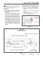
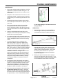
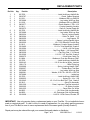
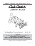
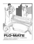
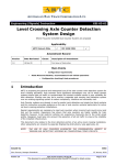
ACCLAIM ® OPERATOR, PARTS, AND INSTALLATION MANUAL BX4330 ACCLAIM® Tow Bar 2 Inch Coupler TOWING PRODUCTS DIVISION Page 1 of 8 292-2205 Rev. I 1/19/12 SAFETY DO NOT INSTALL, OPERATE OR USE THIS EQUIPMENT UNTIL THE FOLLOWING OPERATING AND SAFETY INSTRUCTIONS HAVE BEEN READ AND UNDERSTOOD. This symbol is used to bring attention to safety precautions and instructions. When you see this symbol, be alert and pay attention to all instructions. YOUR PERSONAL SAFETY IS INVOLVED. 1. Blue Ox tow bars are designed for the coupler to be parallel to the ground when towing. If the tow bar coupler is at an angle, damage or accident could occur. 2. Blue Ox tow bars are designed to tow manual transmission cars or automatics equipped with a transmission pump, drive shaft disconnect or half shaft disconnect. 3. Set the transmission for towing according to the owners manual. Verify recreational towing procedures in the vehicle owners manual. 4. Unlock the steering wheel to allow the front wheels of the towed vehicle to “track”. Be sure the front end of the car being towed is properly aligned. 5. The use of safety cables or chains is required by law in some states of the United States and territories of Canada. Check with the states or territories that you plan to travel through prior to your trip. Blue Ox strongly recommends the use of safety cables (BX88196 or BX88197) and our permanent baseplate safety cables (BX88207 or BX88208) with all applications of towing. Please refer to their specific installation instructions for more information. 6. Adjust the coupler for proper fit to the ball (see coupler fit adjustment). For added security, place a lock, pin or bolt through the hole provided in the coupler locking lever. A BX8860 padlock is recommended. 7. Check clearance between vehicles in a turning situation. 8. Rear lighting is required on the towed car. A BX8811, BX8847 or BX8869 Wiring Kit is recommended. 9. Prior to towing be sure all towing accessories and attachment points are secure. Check for cracked COUPLER FIT ADJUSTMENT (Unlocked Position) Locking Lever (Locked Position) Housing Pin & Chain (Optional) Light Spring Ball Clamp Heavy Spring Lock Nut Channel Lock 1.Using a 3/4" socket, tighten or loosen the nut until firm contact between coupler and ball is established. 2.Check ball to housing tension periodically and tighten if needed. 3.Lightly lubricate the ball. Page 2 of 8 292-2205 Rev. I 1/19/12 welds and loose or worn bolts/ pins on baseplate and tow bar. This is important on all occasions but particularly on a new installation, when they should be checked just prior to initial towing and again after 100-200 miles of towing. 10. Do Not Back Up when towing. Damage to both vehicles and towing system may occur. 11. Avoid sharp turns and rough terrain. Check towing system after unusual events and periodically on long trips. 12. Do not use towed vehicle for storing luggage, etc.; you may exceed the towing capacity of the tow bar. SAFETY CABLE INSTALLATION 1. Using the cable hooks, attach the cables to a solid part of the chassis of the towed vehicle or to the convenience links. Slip the end of the hook through the neoprene keeper to prevent the hook from unhooking. (See Fig. 3) NOTE: It is best to have permanent chains that connect the convenience links to the frame of the car. (See Fig. 2) 2. NOTE: Do not wrap safety cables around legs or damage could occur to rubber boot. If it is necessary to remove slack from the cables, wrap each once around their respective tow bar leg in front of the latch housing and then cross them under tow bar. (See Fig. 1) 3. Using the cable hooks, attach the opposite ends of the cables to a solid part of the chassis of the towing vehicle if at all possible. Slip the end of the hook through the neoprene keeper to prevent the hook from unhooking. (See Fig. 3) 4. Adjust slack so that the cables cannot touch the ground or become caught beneath the ball. If either of these things happen, the cables may become damaged and ineffective. DO NOT USE DAMAGED CABLES! 5. Be sure each cable or chain used has at least the load rating of the coupler. INSTALLATION / ADJUSTMENT CAUTION: As with any mechanical product, care should be taken during installation and operation, to prevent your fingers from being pinched. INSTALLATION NOTE: The Acclaim may only be used with removable tab baseplates that have 23" or greater spaced tabs. Warning: If quick pin ring is not folded to the nose side of the quick pin it is not in the locked position. 2. Extend the tow bar legs (See Hooking-Up To Towing Vehicle section) and place coupler over the two inch ball. 3. Fold the tow bar for storage. (See Unhooking/ Folding section) 1. Refer to figure 1 while installing the tow bar. Hold the tow bar in position aligning the triple lug (with holding pin) onto the passengers side attachment tabs. Insert the 1/2 inch pin through the attachment tab and triple lug and secure with quick pin assembly, folding the quick pin ring down to the nose side. Refer to figure 2. Next hold the coupler end of the tow bar to the drivers side attachment tabs. Align the coupler holding bracket (on under side of coupler) between the driver side attachment tabs and insert the 1/2 inch pin through the tabs and bracket. Secure the 1/2 inch pin with a quick pin assembly, folding the quick pin ring down to the nose side. Refer to figure 2. 4. DEALER OR INSTALLER: BE CERTAIN USER RECEIVES TOW BAR MANUAL. DRIVERS SIDE SHOWN Figure 2 ACCLAIM STORAGE POSITION Figure 1 Page 3 of 8 292-2205 Rev. I 1/19/12 HOOKING UP / EXTENDING HOOKING-UP TO THE TOWING VEHICLE Make sure you are able to identify the tow bar parts, (Figure 1), before proceeding. 1. Position the towing vehicle on a level surface and engage the parking brake. (Later, You will be driving straight ahead to latch the legs when extending the tow bar.) Position the towed vehicle behind the towing vehicle in the approximate towing position and Figure 3 engage the parking brake of the towed vehicle. 2. Pull the top tow bar leg off the holding pin of the other leg. 3. Extend the coupler and adjust correctly (See Coupler Fit Adjustment page 1) onto the 2" inch ball and push down to lock the coupler locking lever. Insert coupler pin or padlock to prevent locking lever from releasing. Important: For safety, you should put the coupler pin provided, a padlock or a bolt with nut through holes on the coupler lever. A BX8860 padlock is recommended. NOTE: If only one locking handle is locked turn the towed vehicle's steering wheel towards the unlocked side approximately 1/2 to 3/4 turn. Pull the towing vehicle forward one to two feet until the leg locks into place. IMPORTANT: Check to insure both legs are latched properly before towing. The steering wheel on the towed vehicle must be unlocked at all times while being towed. Failure to do so will create hazardous driving conditions. 2. Install safety cables or chains and lighting. (See safety cable installation - page 1). UNHOOKING / FOLDING 1. Park the towing vehicle with vehicle in tow, in a straight line, on a flat, level surface to insure minimum pressure is exerted on the tow bar legs. This will aid in releasing the locking handles. Engage the towing vehicle parking brake. Place the towed vehicle either in park for automatic transmissions or securely in first gear for manual transmissions. Unhook the lighting and safety cables. 2. Push straight down on the end of the locking handles to release tow bar legs. 3. Remove the clip or lock from the coupler locking lever and lift up. Lift the coupler off the ball on the hitch. 4. Extend the other tow bar leg over to the vacant attachment tab and insert the half 1/2" pin through the triple lug and the tabs. Insert the quick pin assembly into the half inch pin folding the ring knob side down. See Figure 2 of the Installation section. EXTENDING TOW BAR Caution: It is possible to extend the tow bar by driving away with the towing vehicle. This can cause the towed vehicle to wander from side to side and does not insure that the legs will lock into position. We DO NOT recommend towing any vehicle until the operator has confirmed that the leg latches have been properly locked as outlined below. Figure 4 1. On the towed vehicle disengage parking brake, set up the transmission for towing, (See SAFETY section - Page 1) and unlock the steering wheel. Pull forward with the towing vehicle until one or both of the locking handles are engaged and locked. (When locked the handles will "pop" up) Page 4 of 8 292-2205 Rev. I 1/19/12 4. With the coupler removed from the ball and the leg handles unlocked, slide the tow bar forward and remove the 1/2" pin from the drivers side leg. Bring the leg over to the passenger side and set the triple lug onto the holding pin of the opposite leg. 5. Bring the coupler over to the drivers side attachment tabs and pin together the holding bracket and the attachment tabs. FOLDING / MAINTENANCE MAINTENANCE 1. This tow bar requires periodic maintenance. It will be subjected to road dirt and weather during use. The following tips will help maintain the condition of your new tow bar. 2. Keep the tow bar covered when not in use, on or off of the towing vehicle. This will cut down on the dust and dirt build up on the inside legs and latches of the tow bar. 3. Periodically clean the entire surface of the tow bar with a mild soap and water solution. Wipe dry with a clean cloth. 4. Prior to each towing trip check to be sure all the towing accessories and attachment points are secure. Replace any bolts or pins that may be worn. If a nylon inserted lock nut is removed, replace with a new one. 5. Check for cracked welds and loose bolts on the baseplate, towed vehicle (where baseplate is bolted) and the hitch on the towing vehicle. Figure 5 is at an angle, damage or accident could occur. See figure below. LUBRICATION 1. Approximately once per year or if it is difficult to move the legs in and out you should remove the small cable ties holding the rubber boots on the 6. Do not back up when towing, the towed vehicle may jack knife causing abnormal stress to the tow bar, car chassis, baseplate and hitch receiver of the towing vehicle. 7. In normal straight line towing conditions, both legs will be in tension. Due to the design of the latch, both handles will feel loose. During turning, braking or parking one or both of the legs may be in compression. This will make the handles feel stiff or tight. Due to parking on slopes or the angle between the coach and the car, the two locking mechanisms could be in compression or tension or any combination of the two. Having one lock in tension and one in compression may give the operator the feeling that one leg is locked and one is not, when in fact whenever the legs are fully extended and the springs are holding the latch handles up, the legs are locked and ready to tow whether in tension or compression. legs and slide the boots back. Wipe clean each inside leg and apply a light coat of multipurpose grease to insure smooth operation. Secure each boot back in place with an 8 inch nylon cable tie (available at most automotive and hardware stores). See Figure 6. 2. All other pivot points should be cleaned, sprayed with silicon and allowed to dry before using. If you are using the Towbar in a harsh environment, these recommendations need to be done more often. 8. The Acclaim tow bar is designed for the coupler to be parallel to the ground when towing. If the tow bar coupler is at and angle, damage or accident could occur. Drop receivers of 2, 4, 6, 8 and 10 inches (BX88128 through BX88132) are available through any Blue Ox dealer or distributor. See Figure 5. 9. Blue Ox tow bars are designed for the coupler to be parallel to the ground when towing. The height difference from the center of the attachment tabs to the center of the 2" ball on the towing vehicle should be approximately 7 inches. If the tow bar coupler Figure 6 Page 5 of 8 292-2205 Rev. I 1/19/12 REPLACEMENT PARTS Page 6 of 8 292-2205 Rev. I 1/19/12 REPLACEMENT PARTS Parts List Ref. No. Qty. Part No. Description 12 62-3750..........................................................................Latch Hndl Assy, Ald/AV2/Alx 21 292-0797................................................................................Decal, Cables Required 31 61-5121............................................................................Weldment DS Leg, BX4330 44 207-0908............................................................................ Leg Inside, With Leg Stop 51 61-5120............................................................................ Weldment PS Leg, BX4330 62 290-0377.........................................................................Plastic Washer, 1 OD x 1/16 71 61-5411..............................................................................Coupler Assembly, Acclaim 293-0273.......................................................................... Class III Coupler Repair Kit 82 62-3750..........................................................................Latch Hndl Assy, Ald/AV2/Alx 92 207-0908............................................................................ Leg Inside, With Leg Stop 102 299-0234................................................................................ Swivel, Locking Handle 112 290-0364.................................................................................Cable Tie, Black, .3 x 9 121 299-0250............................................................................................Leg Support, ZP 132 290-0394.................................................................... Spacer, Locking Handle, Nylon 142 229-0520................................................................ 1/2 x 2 5/8 Effective Pin with Ring 151 61-5413.............................................................. Weldment, Coupler Spacer, Acclaim 162 201-0490.............................................................. 1/2-13 x 3 Hex Head Bolt, Grade 5 172 201-0504................................................................................. 1/4-20 x 1/4 Set Screw 184 290-0332............................................................ Cap Plug, Black, 1 1/4 Square DMC 192 290-0328.........................................................................Cap Plug, Red, 1 1/2 Round 202 201-0369................................................................. 1/2-13 x 3 1/2 Hex Bolt, Grade 5 212 290-0275................................................................................. 8 Inch Nylon Cable Tie 222 61-5484............................................................. Weldment, Pivot Arm Receiver, DMC 232 62-3750..........................................................................Latch Hndl Assy, Ald/AV2/Alx 246 202-0143................................................................1/2-13 Hex Nut w/ Nylon, Jamlock 252 100-1176............................................................................................ Offset Triple Lug 262 222-0068...................................................................... Spring, Locking Handle, DMC 272 250-0227.................................................................................Rubber Boot, Tow Bars 282 207-0908............................................................................ Leg Inside, With Leg Stop 294 290-0381......................................................... Washer, 0.531 ID x 3/8 OD x 0.05 Thk 302 207-0688..................................................................................................... Inside Leg 312 62-3750..........................................................................Latch Hndl Assy, Ald/AV2/Alx 322 220-0033.................................................................................. Spring Pin, 1/4 x 1 3/8 332 201-0645..................................................... 1/2-13 x 2 Hex Bolt, Shrt. Thrd., Grade 5 342 62-3213........................................................................................Quick Pin Assembly 351 292-1206...........................................................Decal, Important, Tow Bar Instruction 361 292-2203........................................................................................ID Sticker, Acclaim 372 292-1035...................................................................................Decal, Blue Ox, White 381 84-0055........................................................................ Kit, Driver Side Leg Assembly 391 84-0056.................................................................Kit, Passenger Side Leg Assembly 402 201-0699............................................................ 1/4-20 X 1/2 Set Screw, Knurled, ZP IMPORTANT: Use only genuine factory replacement parts on your Tow Bar. Do not substitute homemade or nontypical parts. If a bolt is lost or in need of replacement, for your safety and the preservation of your Tow Bar, be sure to use a replacement bolt of the same grade (Usually Grade 5). Repair parts may be ordered through your nearest Automatic dealer or distributor. Page 7 of 8 292-2205 Rev. I 1/19/12 QUICK REFERENCE GUIDE HOOKING UP & EXTENDING FOR TOWING UNHOOKING & FOLDING FOR STORAGE 1. Align vehicles in towing position with straight driveway ahead and parking brakes locked. 1. Park vehicles in a straight line on level surface. Apply towing vehicle parking brake. Place towed vehicle in park or 1st gear for manual transmissions. 2. Place ball coupler on 2 inch ball. Pin legs to attachment tabs. 3. Drive towing vehicle forward until both legs are locked. (Locking Levers Up) 2. Remove safety cables and towed vehicle lighting. 4. Install safety cables and towed vehicle lighting. 3. Disengage leg latches. Unpin drivers side leg from attachment tabs and place triple lug on holding pin of opposite leg. Pin coupler brace into empty attachment tab and pin in place. 5. Detailed instructions appear on pages 3-4. 4. Detailed instructions appear on page 4. TO BE VALID, THE WARRANTY CARD MUST BE COMPLETED IN ITS ENTIRETY BY AN AUTHORIZED DISTRIBUTOR OR DEALER AND SENT TO AUTOMATIC EQUIPMENT MFG. CO., PENDER, NEBRASKA. FAILURE TO DO SO WILL VOID THE WARRANTY. Repair parts may be ordered through your nearest Automatic dealer or distributor. Product Safety Policy Statement It is, and shall continue to be, a primary objective of Automatic Equipment Manufacturing Company to provide customers with safe and reliable products. Automatic will, and has, established safety procedures in product design, manufacture, promotion and sales; and will coordinate efforts to promote customer safety to the greatest extent possible. Each department has primary responsibility for the promotion of safety under the guidelines of the Product Safety Committee. WARNING: Ensure that your towing vehicle is of adequate size to properly control your towed vehicle. The weight and braking capacity should be large enough to handle both vehicles in an emergency situation. Check your towing vehicle manufacturers recommendations for towing, hitch load, and braking capacities. The hitch, ball, motorhome chassis, and safety cables (each individual cable) need to be rated at a minimum for the weight of the vehicle being towed. Page 8 of 8 292-2205 Rev. I Automatic Equipment Mfg. Co. One Mill Road, Industrial Park 1/19/12 Pender, Nebraska 68047 © 1999, 04, 07, 08, 09, 11 Automatic Equipment Mfg. Co. Pender, NE 68047