1
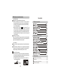
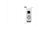
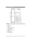
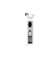
SMART
SENSOR
R
Model AR854
Digital Sound Level Meter
User's Manual
Version: SZ854-1
Precauction
Thank you for pruchasing
meter.
Digital sound level
This manual provides relative information on how
to use the unit and warnings in operation.
To make the best use of this product's functions,
read this manual thoroughly before use. Please
keep this manual quick reference.
Please make some simple test measurement to
ensure proper performance of the unit.
Maintenance and warranty
1). Maintenance
Replacement and maintenance of battery:
a.Remove the battery from the unit if it is not required for
extended periods of time in order to avoid damage to
the battery compartment and the electrode resulting
from a leaking battery.
b.After power on, if a symbol
appears on the LCD, you
need to replace the batteries immediately. Open the battery door, take out the old battery install new batteries,
(note the battery polarity), then close the battery door,
for details please refer figures and contents on page 10
of this manual.
Cleaning the casing:
Never use alcohol or thinner to clean the unit casing that
will especially erode the LCD surface; just clean the unit
lightly as needed with little clean water.
Contents
1. Before use notice
2.Operation instructions
2). Warranty
About relative warranties please read provided warranty
card.
We disclaim any liability due to: transportation damages;
incorrect use or operation; manipulation, alterations or
repair attempts; without warranty card, invoice.
Specific Declarations
a. We reserve the rights of the update and amendment
of the product design and the manual which are subject
to change without further notification.
b. Dispose of battery should in accordance with local
laws and regulations.
-31-
3. Other items
Familiar trouble shooting ------------------------(30)
Attentions ------------------------------------------(30)
Maintenance and warranty ----------------------(31)
Special declaration -------------------------------(31)
1. Before use notice
3. Other items
Familiar trouble shooting
Check-up
Carefully unpack your kit after you purchased this product
and ensure that you have the following items. In the event
that any item is missing or if you find any mismatch or damage or the manual appearing to lack page, etc. seriously influencing the reading, promptly contact your dealer.
Sound level meter
1PCS
Sponge ball
1PCS
Computer software disc
1PCS
USB connection cable
1PCS
1.5V battery (AA)
4PCS
EN user's manual
1PCS
Warranty card
1PCS
PP packing box
1PCS
The following is a list of actions to be taken if the unit is not
working properly:
1). Screen is Blank:
Check the batteries are installed correctly. Open the
battery door on rear of the unit. The + and - symbols on the
battery should match the corresponding + and - symbols
marked in the battery compartment.
2). If the unit can not connect to PC normally, please check
if the USB cable is OK, if the cable can not be used formally,
please replace it for a new one.
Attentions
1). Environment conditions on operation:
Indoor use;
2000 meters high below;
Temperature:0~40
Relative humidity: 80%RH
2). Do not store or use the unit in following conditions:
a. Splashes of water or high levels of dust.
b. Air with high salt or sulphur content.
c. Air with other gases or chemical materials.
c. High temperature or humidity or direct sunlight.
3). Never impact the unit or used on humidity conditions.
-01-
-30-
5) On line measurement:
Introduction
Click Real Time Measure in File menu bar or Real Time
Measure button in tool column will enter into the window
as shown in figure 24:
Figure 24
Supervision window of sound level meter displaying
Real time measurement
carve diagram
This unit has been designed to meet the measurement
requirement of noise engineers, noise quality control and
health prevention in various environments. Such as noise
measurement in factory, office, traffic road, family and all
other noise measurement applications.
Features and function
Real time data
collection each
sound
Button instructions:
Button
Function
Click to start real-time measurement
Click to stop real-time measurement
Click to clear all the measuring data
Click to store real-time measuring data, input file
name in popup window, click to save the document
format of Lab.
Click to print curve diagram
Zoom in curve diagram
Zoom out curve diagram
Reset zoom, resume to defaulted value
Move curve diagram to left or right
This software supports to print measuring data curve
diagram, for details please refer to HELP content.
-29-
-02-
4) Connection with PC:
Diagram of the unit
12
DC OUT
13
Insert one end of USB wire into the USB socket on the
unit, as shown in figure 22
D C I N AC OUT
USB
Figure 22
SMART
SENSOR
R
SOUND LEVEL METER
14
M
F/S
Plug another end of USB wire into the interface port on
PC, as shown in figure 23
L ig
ax
CL ht
R
ON
OFF
Figure 23
REC
HOLD
1. Sponge ball (when outdoor use please put on, prevent
wind blowing noise disturbing the unit reading)
2. Prepolarized condenser microphone
3. LCD
4.
ON
OFF
5.
ax
M
: ON/OFF button
: Max function button
Note:
Once the connection is done, an USB icon appears on
the LCD of the unit indicates a success connection,
otherwise, the connection fails.
In connection with PC, the PC could supply the power
to the unit directly, in absence of 4 *AA batteries .
-03-
-28-
3) Software instruction
The software window as shown in figure 21
Menu
bar
6.
7.
: Fast / Slow time weighting switch
F/S
Li
CL ght
R
: Black-light and clear stored data button
(Press and hold for 2 seconds will clear the
Tool
column
stored data)
State
column
Figure 21
Note:
Check if this unit is connected well with the computer on state
column:
Connect OK: Connect successful;
Disconnect: failed to connect.
8.
REC
9.
HOLD
: Data store button (10000 storage)
: Data hold button
10.DC OUT : DC signal out(10mv/dB, impedance 500
Tool column instruction as shown in following diagram:
11.
Button Function
USB
: USB socket
12. DC IN : DC 4.5~9V input jack(outside P, inside N)
Real-time data measurement, the measured data in real time
will be displayed on computer screen
Download the data stored in the sound level meter to computer
Open measuring data file that is saved as Lab format
13. AC OUT : AC signal out put
14. Battery door
Save real-time measurement data
Save the measured data as Excel document
Print data sheet
System setting
Note:
Above key functions descriptions just are simple introduction, please read operation instructions part in this
manual for details.
Help
System information
Close this software
-27-
-04-
LCD display
14
13
12
dB/1
11
10
Figure 20
Finish
Note:
If you want delete this software, please open the
"control panel", then open the "add/delete program" to
select VoiceLAB in the list, click the Delete button to
remove the software.
-05-
-26-
Specifications
Figure 19
Cancel
If appears following picture, click Finish, the quick way of
starting software will produce automatically on the
tabletop, whose name is VoiceLAB,
as shown in figure 20:
-25-
Microphone
Sensitivity
Calibration
Measurement range
Accuracy
Frequency
response
Resolution
Over load indication
Frequency weighting
Digital display
Time weighting
Data store
Maxi reading
Auto power off
Power
Dimension
Net weight
Battery life
-06-
Calibration
Please use 94dB@1KHZ standard calibration instrument
Setting on sound level meter:
Frequency weighting is A;
Time weighting is FAST;
Insert the microphone head into the standard calibration
jack, set the standard source as 94dB@1KHZ, use a
small - screwdriver adjusts the calibration knob at the
round hole until LCD display93.8, as shown in figure1
Calibration knob
SMART
SENSOR
Figure 18
Install
R
SOUND LEVEL METER
In program installation process, if want stop it, please
click the Cancel button, as shown in figure 19:
M
F/S
L ig
ax
CL ht
R
ON
OFF
REC
HOLD
Figure 1
Note:
This unit has been calibrated before leaving factory, one
year calibration cycle is recommended.
-07-
-24-
2. Operation instructions
Battery installment
Open the batter door insert the 4PCS 1.5V batteries
into compartment properly, (note the battery polarity),
as shown in figure 2:
Figure 2
Figure 17
Next
Click the Install button to install the program into your
PC, as shown in figure 18:
-23-
-08-
Measure of sound level LP
Enter the user name and company name, click NEXT to
enter Next step, as shown in figure 16:
ON
OFF
Figure 3
Figure16
Next
Figure 4
Setup type selection, select the defaulted setup
(Complete) type, click NEXT to enter Next step,
as shown in figure 17:
-09-
-22-
Connection with PC
1). Requirements of computer configuration:
CPU: Pentium 600MHZ or above;
One free available USB connecting interface:
The lowest screen resolution of monitor is 800*600 (or
much higher), true color;
At least 8MB available memory;
At least 50MB available disk memory;
Operation system: MICROSOFT WINDOWS 98/ME/2000
/ XP HOME/XP Professional 32Bit
2). Installing the data collecting software:
Place the software disc in your disc driver, open the disc
driver file, double-click the Setup.exe program icon to enter
program installation contact interface, click NEXT to enter
Next step, as shown in figure 15
Figure 5
Figure 6
Figure 15
-21-
Next
-10-
Time weighting selection
It is defaulted as FAST after power on, the LCD
Figure D:
AR854 with a sponge ball in the absence of wind,
at free-field response in several incidence direction.
screen displays as in figure 7:
Figure 7
Press the
F/S
key it turns into SLOW , the LCD screen
displays as in figure 8
Figure 7
Note:
a.Selecting FAST is to pick up the current reading;
b.Selecting SLOW is to pick up the reading of average
within 1 second.
-11-
-20-
Figure C: A free-field response of AR854 integrating
sound level meter in several incidence direction
The maximum value Lmax measurement
During measurement process, press the Max key to lock
up the maximum reading, the LCD displays as in figure 9
Figure 9
Press it once again to exit the maximum value measurement and return normal measurement mode.
Data hold
Press
, LCD will show HOLD icon and lock the
current reading, as figure 10
HOLD
Figure 10
-19-
-12-
Data storage
REC
Figure 11
The memory capacity is 10000, after long period of
recording, the LCD screen will appear the symbol FULL,
as shown in figure 12
Figure 12
Figure B: Nominal A-frequency weighting cure
Press
the LCD screen appears the symbol RECORD
flashing, indicating that the unit enter into the data
storage mode, LCD screen displays as in figure11
In data storage process or recording memory is full, press
this key again to exit the record mode, the flashing
symbol RECORD disappears.
-13-
-18-
Figure A: Nominal free-field response of AWA14425
microphone in reference incidence direction
Data clearance
Press down the
Li
CL ght
R
key until the LCD screen displays
the symbol CLR, then all recorded data will be deleted,
LCD displays as in figure 13:
Figure 13
-17-
-14-
Information for testing
DC adaptor
There is a DC socket for the DC adaptor, when
connect with the DC adaptor the meter will auto
cut the battery power. The DC power supply range
is 4.5V to 9V(outside P, inside N)
When the meter is for long period measurement,
please use the DC adaptor power supply.
Figure 14
Use of sponge ball
-15-
(1) Reference sound pressure: 94dB
(2) Reference incident direction: axial of microphone
(3) Reference point: diaphragm centre of micophone
(4) Adjustment data to obtain a-weighted sound levels
equivalent to response to free-field response to plane
sinusoidal sound waves incident from the reference
direction.
Frequence(Hz)
1k
1.25k
1.6k
2k
2.5k
Adjustment(dB)
0.2
0.3
0.4
0.5
0.6
3.15k
0.8
Frequence(Hz)
4k
5k
6.3k
8k
10k
12.5k
Adjustment(dB)
1.0
1.55
2.1
3.2
4.5
6.2
(5) Nominal free-field response of the meter on reference incident under approximate reference conditions.
(6) Electrical input equipment: 20pF condenser
(7) Highest self-generated noise level:28dB(electrical
noise level is not higher than 25dB).
(8) Allow highest sound pressure level on microphone:
132dB
(9) Maximum input peak voltage of electrial input
equipment: 4Vp-p
(10)Working voltage range at which the sound level
meter confirms to specifications: 4.5V-6.5V
(11)The typical time interval needed to stabilize after
changes in environment condition, at least 12 hours to
be steady under reference requirement, or at least 19
hours in other ambient conditions.
-16-