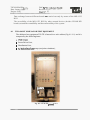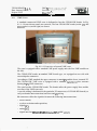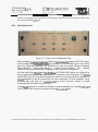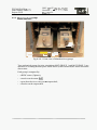
1
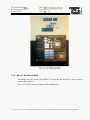
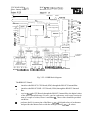
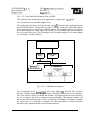
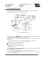
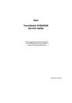
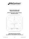
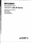
Common European Space Automation and Robotics controller
Hardware development
CESAR HW
Executive Summary
Contract: CCN 06 to ESTEC contract n. 10487/93/NUJG
t
CE-HWSA-TS-011 rev. January 2003
ESA CONTRACT No:
SUBJECT:
CCN n. 6 to
10487/93/NWJG
contract
ESA CR No:
STAR CODE:
NAME OF CONTRACTOR:
n. CESARHW
TECNOSPAZIO
No of Volumes:
CONTRACTOR’S REFERENCE
This is Volume No:
CE-HW-SA-TS-011
The Controller for European Space Automation and Robotics (CESAR) in hardware and software is a projec
developed by ESA to carry out a generic robot electronic controller core, which could be used for diverse space
robotic missions.
CESAR hardware implementation makes maximum reuse of already existing SPLC (Standard Payload Computer
boards and it represents a specialised extension devoted to robot control.
Partners involved in the project were: TECNOSPAZIO (Prime Contractor and system designer and tester), ASTRIUM
and GALILEO AVIONICA (boards designers and developers).
The architecture of CESAR is composed of a Robot Control Unit (RCU), which performs the most computatior
intensive high level tasks, and a set of intelligent slave modules, named Servo Control Units (SCU), which control thc
robotic hardware (motor servo drives, sensors). Both RCU (which is the standard SPLC CPU board) and nem
mezzanine CPU board of CESAR HW (SDC board devoted to govern the SCU) are based on SPARC-chipset ERC32.
A multi-drop master-slave serial bus (MIL-Bus 1553B) is adopted to allow for communication between RCU anc
SCUs. This serial bus enables both the concentrated and distributed control. CESAR HW is the platform on whicf
CESAR SW operates. In the frame of this project, the CESAR SW (formerly running on a SPARC based Force
computer) has been ported and tested to the CESAR HW platform (ERC32 based boards).
Testing of CESAR HW boards (inserted into a dedicated test equipment) have been performed using CESAR SW tc
govern the movement of a robot arm simulator (ROBCAD model) and in parallel a couple of real joint motor/sensoi
groups (to effectively test board input/outputs). CESAR SW has been configured to move Comau SMART-3 anc
Mitsubishi PA-10 robot arms.
Main requirements of CESAR HW (development of electronic boards to control a robot arm with up to 8 joints, wit1
servo brushless motor and resolvers, to realise compact but distributed or concentrated architecture, porting and testing
on this architecture of CESAR SW to execute robot manipulation programs) has been fully respected. The developec
boards are ground models, designed using components which have a high-re1 version (compatibility was required foi
dimensions, functions, shape and PIN function). Eventually future development of an equivalent flight unit versior
will be easily implemented.
NAME OF ESA STUDY MANAGER::
ESA BUDGET HEADING:
Gianfranco Visentin
DIY:
MM
DIRECTORATE:
D/TOS
TECNOSPAZIO S.p.A.
Date: January 2003
Project: P128
DOC. No: CE-HW-SA-TS-011
Revision : SheetN": 1
Title:
CESAR HW
Executive Summary
Project:
CESAR HW
Contract:
CCN n. 6 to ESTEC contract n. 10487/93/NL/JG
Function
Prepared
By : Engineering
Name
R. Baldassarre
By :
Checked
By:
By:
~
Approved
By : Program Manager
R. Baldassme
By :
Authorised By : General Manager
Configuration
Management :
Accepted by :
L. Giardino
Rev.:
Date:
TECNOSPAZIO S.p.A.
Date: January 2003
Project: P128
DOC. No: CE-HW-SA-TS-011
Revision : SheetN": 2
CHANGE HISTORY RECORD
File name:
CH-Sum-Rep-011
.doc
TECNOSPAZIO S .P.A.
Date: January 2003
Project: P128
DOC. No: CE-HW-SA-TS-011
Revision : SheetN": 3
REVISION INDEX OF SHEETS
TECNOSPAZIO S.p.A.
Date: January 2003
Project: P128
DOC. No: CE-HW-SA-TS-011
Revision : SheetN": 4
DISTRIBUTION LIST
Internal Distribution
External Distribution
DOC. No: CE-HW-SA-TS-011
Revision : SheetN": 5
TECNOSPAZIO S.p.A.
Date: January 2003
Project: P128
LIST OF CONTENTS
INTRODUCTION
I
1.1
Overview
6
1.2
List Of Acronyms
8
1.3
Documents
9
2
REQUIREMENTS
FUNCTIONAL AND PERFORMANCE REQUIREMENTS
10
2.2
ENVIRONMENTal Requirements
10
2.3
RESOURCE Requirements
10
CESAR HW DESCRIPTION
3.1
3.2
11
Developed Boards
SDC
RB-SCU Base Board (RBB)
ADIO-SCU Base Board
16
16
18
21
3.2.1
3.2.2
3.2.3
SYSTEM PERFORMANCES
4.1
14
15
24
Two Joint Simulator Test Equipment
W E Crate
Power Driver Unit
Distribution Unit
Motorhesolvers groups
25
GENERAL TESTING APPROACH
30
4.1.1
4.1.2
4.1.3
4.1.4
4.2
11
General CESAR-HW Architecture
Robot Control Unit (RCU)
SCU
3.1.1
3.1.2
5
10
2.1
3
4
6
CONCLUSIONS AND PERSPECTIVES
26
27
28
29
32
TECNOSPAZIO S.p.A.
Date: January 2003
Project: P128
1
1.1
DOC. No: CE-HW-SA-TS-011
Revision : SheetN”: 6
f
INTRODUCTION
OVERVIEW
This document summarises the activities performed under the “Space Robotics
Components Development (part I ) - CESAR (Common European Space A&R
controller)”, CCN n. 6 to ESTEC contract n. 10487/93/NL/JG - CESAR-HW (plus the
following CCN8 and CCN 10 to the same contract).
The main objectives of the contractual activity were to develop and hctionally test a
ground model of CESAR-HW.
The Controller for European Space Automation and Robotics (CESAR) in hardware and
software is a project developed by ESA to carry out a generic robot electronic controller
core, which could be used for diverse space robotic missions.
CESAR hardware implementation makes maximum reuse of already existing SPLC
(Standard Payload Computer) boards and it represents a specialised extension devoted to
robot control.
In addition to already existing SPLC boards, CESAR HW project has developed a
minimum set of board to built a eight joints robot controller unit.
CESAR HW is the platform on which CESAR SW operates. In the frame of this project,
the CESAR SW (formerly running on a SPARC based Force computer) has been ported to
the CESAR HW platform (ERC32 based boards).
Testing of CESAR HW boards (inserted into a dedicated test equipment) were performed
using CESAR SW to govern the movement of a robot arm simulator (ROBCAD model)
and of a couple of real joint motor/sensor groups
Partners involved in the project were:
TECNOSPAZIO, as Prime Contractor and Technical Coordinator, responsible of the
following activities:
- Project management and technical co-ordination
- System requirements and architecture
- System integration and testing
TECNOSPAZIO S.p.A.
Date: January 2003
Project: P128
DOC. No: CE-HW-SA-TS-011
Revision : SheetN": 7
ASTRIUM, responsible of:
- Procurement of board re-used from SPLC projects
- Design and development of servo CPU board and inputloutput board
GALILEO AVIONICA, responsible of:
- Design and development of the board to interface the robot drivers and sensors.
TECNOSPAZIO S.p.A.
Date: January 2003
Project: P128
1.2
DOC. No: CE-HW-SA-TS-011
Revision : SheetN": 8
LIST OF ACRONYMS
A/D
AnalogueDigital
AD10
AnalogDigital Input/Output
ADIOB
ADIO-SCU Base Board
ADIO-scu
AnalogDigital Input/Output Servo Control Unit
BLDC
BrushLess Direct Current motor
CESAR
Common European Space Automation and Robotics Controller
CPU
Central Processing Unit
ESA
European Space Authority
ESTEC
European Space Research and Technology Center
FPGA
Free Programmable Gate Array
LAN
Local Area Network
MIL-BUS
MIL-STD-1553 B bus
PCB
Printed Circuit Board
RB
Resolver/Brushless Motor
RB-scu
ResolvedBrushless Motor Servo Control Unit
RBB
RB-SCU Base Board
RCU
Robot Control Unit
scu
Servo Control Unit
SDC
SCU DSP Core Board
SPLC
Standard Payload Computer
VEA
VME Ethernet Adapter Board
VMA
VME MIL-Bus Adapter Board
VME
Versa Module Europe
vsc
VME Sparc Core Board
TECNOSPAZIO S.p.A.
Date: January 2003
Project: P128
1.3
DOC. No: CE-HW-SA-TS-011
Revision : SheetN”: 9
DOCUMENTS
[RDl]
CESAR-HW System Requirements Document, CE-HW-RQ-TS-001, rev. B
[ID21
C. Taylor, H. Konig and U. SchloSstein, “Standard Payload Computer for the
International Space Station”, ESA Bulletin 93, February 1998.
[RD3]
CESAR-HW TJS - Test Equipment User Manual, CE-HW-MU-TS-008, rev. -
TECNOSPAZIO S.p.A.
Date: January 2003
Project: P128
2
DOC. No: CE-HW-SA-TS-011
Revision : SheetNO: 10
REOUIREMENTS
CESAR-HW requirements are specified in RD1. Main requirements are summarized in
the following.
2.1
FUNCTIONAL AND PERFORMANCE REQUIREMENTS
CESAR HW shall control automation and robotics systems with up to eight joints.
CESAR-HW shall run the CESAR-SW in order to execute robot manipulation programs.
CESAR HW shall support both concentrated and distributed layout.
The CESAR-HW shall command brushless DC motors via the corresponding servo
control drive electronics (not part of CESAR-HW).
The CESAR-HW shall read the output joint positiodspeed sensors such as resolvers and
potentiometers.
The CESAR-HW shall control other non robotics controlled HW via dedicated electronics
boards attached on the internal bus (such boards are not included in the current CESARHW configuration).
2.2
ENVIRONMENTAL REQUIREMENTS
The ground CESAR-HW shall be designed and manufactured to work in normal
laboratory environment.
The flight CESAR-HW (not developed in the present contract) shall be designed and
manufactured to survive launch loads and to work in external outer space of the ISS.
2.3
RESOURCE REQUIREMENTS
The volume of the CESAR-HW will not exceed 11000 cm3.
The mass of the CESAR-HW will not exceed 7 kg.
The peak power absorption of the CESAR-HW will not exceed 68 W.
DOC. No: CE-HW-SA-TS-Ol l
Revision : SheetN": 11
TECNOSPAZIO S.p.A.
Date: January 2003
Project: P128
3 CESAR HW DESCRIPTION
3.1
GENERAL CESAR-HW ARCHITECTURE
The architecture of CESAR (Fig. 3.1-1) is composed of a Robot Control Unit (RCU), which
performs the most computation intensive high level tasks, and a set of more or less intelligent
slave modules, named Servo Control Units (SCU), which control the robotic hardware
(motor servo drives, sensors).
CESAR hardware implementation is based on the SPLC (Standard Payload Computer) of
which it represents a specialised extension devoted to robot control. (SPLC is a multi-board
system based on open VME-bus-standard).
Due to this strict master-slave structure CESAR does not need any sophisticated multiprocessor bus (such as VME). Instead a multi-drop master-slave serial bus (MIL-Bus 1553B)
is adopted to allow for communication between RCU and SCUs. This serial bus enables both
the concentrated and distributed control.
Sensor Inputs
Servo Control
Hardware
L
I
Serial Bus
A
A
A
I
I
v
RCU
Other Controlled
Hardware
Hand
OIB Data
Iing
Fig. 3.1- 1 CESAR general architecture.
The distributed control concept allows for allocation of SCU near the controlled robot joint,
minimising long and complex wiring of motor and sensor groups.
A like SPLC card cages may be utilised to host the CESAR HW board as per concentrated
and distributed control.
CESAR HW project has made use of a minimum set of board (Fig. 3.1-2) to build a eight
joints robot controller unit.
CESAR HW has adopted the same mezzanine board architecture as SPLC, minimising the
development of new boards and optimising the system accommodation.
DOC. No: CE-HW-SA-TS-011
Revision : Sheet No: 12
TECNOSPAZIO S.p.A.
Date: January 2003
Project: P128
t
Both standard SPLC CPU board and new mezzanine CPU board of CESAR HW (SDC board
devoted to govern the SCU) are based on SPARC-chipset ERC32.
m
--.
. --
,
:
.
,
.
I
.
.,
....
,;I
' E
"
-".
The SCUs are designed in a modular manner. Each SCU consists of a Base-Board, a CoreBoard and one Mezzanine-Board.
A Base Board carries Core- and Mezzanine-Boards and provides the required interfaces to
the robot servo amplifiers.
Core-Boards include a DSP CPU, drivers, non-volatile memory and progrddata RAM.
Mezzanine-Boards are used to interface to the serial bus. They feature a micro-controller,
which performs data-communication tasks up to the Application Layer of the ISO/OSI
model. With this arrangement the Core-Board is not affected by the specifics of the serial bus
used.
The RCU and the On-Board Data Handling communicate via an ethernet interface mezzanine
card (but the communication can be performed via 1553 by substituting the ethernet
mezzanine with a second 1553 mezzanine). The Ethernet interface is used also for
development and debugging of the system s o h a r e .
The communication between the RCU and the SCU's has been realised via the MIL-Bus
1z-R.
TECNOSPAZIO S.p.A.
Date: January 2003
Project: P128
DOC. No: CE-HW-SA-TS-011
Revision : Sheet No: 13
All terminals (RCU - SPLC replica - and SCUs) are connected to a single level bus. The
stationary master control philosophy is considered so that the RCU - SPLC replica - (Bus
Controller) will manage the bus communication for all the SCUs (Remote Terminals).
CESAR HW is the platform on which CESAR SW operates. In the frame of this project,
CESAR SW has been ported on the CESAR HW platform (ERC32 CPUs), using the
=Works real-time operating system.
CESAR SW was developed in the frame of the contract Building Blocks for Automation and
Robotics, by starting from a mature, well-proven industrial product: the COMAU C3G
controller.
The CESAR SW architecture (Fig. 3.1-3) features three types of tasks:
- system tasks (implementing the interface to Telemetry/Telecommands, a monitor shell
and some built-in test logic);
-
robotic tasks (robot program interpretation, motion control);
- user tasks (to interface to external auxiliary hardware)
CESAR
Carnands to
Other Tasks
On-board Data
Handling
Mass Memory
Drive & Axis Control
Sensor Interface
e
U
Robot Hardware
(gantry. arm, EE sensors)
Fig. 3.1-3 CESAR software architecture
TECNOSPAZIO S.P.A.
Date: January 2003
Project: P128
DOC. No: CE-HW-SA-TS-011
Revision : SheetN": 14
CESAR SW was developed over the real time operating system VxWorks, which supports
the ERC32 microprocessor family.
The RCU software architecture allows for the easy replacement or addition of tasks to
modify/augment the CESAR functionalities.
The software modularity and the wide micro-processor support for the operating System,
enable the adoption of HW architectures even different from the CESAR general one.
The baseline configuration of the CESAR-HW includes one RCU (SPLC CPU replica), two
RB-SCUs (each one controlling four joints) and one ADIO-SCU.
In the following paragraph the different components of CESAR are described in more
details.
3.1.1 Robot Control Unit (RCU)
The RCU (SPLC replica) is a reuse of the SPLC CPU module in addition with the
mezzanine LAN Adapter and MIL-Bus Adapter.
The RCU consists of four boards:
0
RCU-Base-Board (RSB);
VME-Sparc-Core-Board (VSC);
0
VME-MIL-Bus-Adapter-Board (VMA);
0
VME-Ethernet-Adapter-Board (VEA).
All the above boards are reused from the SPLC project.
RCU-BASE-BOARD (RSB)
/
Fig. 3.1.1- 1: Module layout of the RCU (SPLC replica).
Main characteristics of the RCU are:
TECNOSPAZIO S.p.A.
Date: January 2003
Project: P128
DOC. No: CE-HW-SA-TS-011
Revision : Sheet No: 15
8 Mbytes of SRAM with EDAC;
0
4 Mbytes of EEPROM with EDAC;
14 Mhz ERC32 CPU chipset.
0
3.1.2 SCU
The CESAR-HW distinguishes between different SCU modules, two of them designed in
the frame of current project.
Subject of the present description are the:
0
Resolver-Brushless Servo Control Unit (RB-SCU);
0
AnalogDigital Input/Output Servo Control Unit (ADIO-SCU).
The global concept of these SCU’s is a modular design, which foresee a common core
(SCU-Core-Board), a MIL-STD 1553B interface (VMA) and functional depending base
board (SCU-Base-Board).
In addition, the base board provides the same mezzanine bus concept which is used on the
RCU (SPLC replica).
Fig. 3.1.2-1 shows the foreseen module layout.
SCU-BASE-BOARD (RBB or ADIOB)
,
Fig. 3.1.2-1: SCU module layout.
The RB-SCU is composed of:
0
RB-SCU Base-Board (RBB);
0
SDC;
0
MIL-Bus-Adapter-Board (VMA).
TECNOSPAZIO S.p.A.
Date: January 2003
Project: P128
DOC. No: CE-HW-SA-TS-011
Revision : Sheet No: 16
The ADIO-SCU is composed of:
0
ADIO-SCU Base-Board (ADIOB);
SDC;
0
MIL-Bus-Adapter-Board (VMA).
The VMA is reused from the SPLC projects, while the RBB, SDC anc AD 3B has been
designed and developed in the frame of the CESAR-HW project. They will be described
in the following paragraph.
3.2
3.2.1
DEVELOPED BOARDS
SDC
The SDC is the core CPU mezzanine to be used for both RB-SCU and ADIO-SCU. It
provides the computational power required to perform the servo control and sensor
processingladditional hardware control activities.
The SDC has been designed for the RISC processor TSC695 from the company TEMIC.
This processor is a 32 bit RISC processor based on SPARC 7 architecture, specially
designed for space applications. On of the benefit of this processor is the integrated error
detection and correction with the external EDAC RAM. The TSC695 is the one-chip
version of the ERC32, including the integer unit, floating point unit and memory
controller unit in one package.
This new one-chip controller includes the following features:
-
Full EDAC and parity protection of work memory
Byte wide PROM access
Real Time Clock
General Purpose Timer
DualUART
Wait state generator
Floating Point Unit (IEEE 754)
25 MHz work frequency
Total dose radiation capability of 300 KRAD’s
- SEU event rate better than 1E-8 error/component/day
- Latch-up immunity better than (LET) 1OOMeVcm2/mg.
DOC. No: CE-HW-SA-TS-011
Revision : SheetN": 17
TECNOSPAZIO S.P.A.
Date: January 2003
Project: P128
The SDC is equipped with 4 Mbytes of RAM with EDAC and 2.5 Mbytes of EEPROM.
The SDC is be able to execute the real time operating system VxWorks. Soffware driver
from SPLC mezzanine cards have been reused to the maximum extent.
Fig. 3.2.1-1 shows the block diagram of the SDC.
w
w
I
11
b d d r e s sB
I
kontrol BU$
Boot PROM
Rad-Hard
dKx8Byte
I
1
I
I
2MByte
512kByte EDAC
Controller
FPGA
Interface
+
V
MRC
Interface
MEZ
Interface
II
SDC Connector
I
I
Fig. 3.2.1- 1: SDC block diagram.
A picture of the SDC is given in fig. 3.2.1-2.
TECNOSPAZIO S .P.A.
Date: January 2003
Project: P 128
DOC. No: CE-HW-SA-TS-011
Revision : Sheet No: 18
3.2.2 RB-SCU Base Board (RBB)
The RBB is the base board of the RB-SCU. It provides the interface to joint resolvers
and brushless motors.
Fig. 3.2.2-1 shows the block diagram of the RBB-Board.
TECNOSPAZIO S.p.A.
Date: January 2003
DOC. No: CE-HW-SA-TS-011
Revision : -
-
<
Switch Cmd
1
to SDC
L
to VMA
Mezzanine bus
MRC
output
Res. # 1
bus
Power lines
-
19.53 kHz$fFF
output
output
output
#2
output
#3
Input
--)
4
1L
cos Coarse
Power supply switch
output
Res. # 2
FPGA
I
I
I
Mux
output
Res. # 3
DIGITAL
output
Res. # 4
Input
#2
Input
#3
I -
ll
fi
Phase A
to all Output
Resolvers
Sample and Holders
$ \1
Ph. A Ph. A Ph. A Ph. A
Mot.#l Mot.#2 Mot.#3 M o t M
J
,
\1
Ph. B Ph. B Ph. B Ph. B
Mot.#l Mot.#2 Mot.#3 M0t.M
Sincos Sincos Sincos Sincos
Mot.#l Mot.#2 MOt.#3 M0t.M
M~,$esolvers
Fig. 3.2.2-1: RBB block diagram.
The RBB SCU Board:
a
interfaces the RB-SCU CPU Board (SDC) through the RB-SCU Internal Bus.
interfaces the RB-SCU MIL-1553 Board (VMA) through the RB-SCU Internal
Bus.
receives from the CPU Board, through the RB-SCU Internal Bus, the digital values
of the four Current Reference Vectors - one for each motor; each vector consists in
turn of a couple of values, Phase A and Phase B. These values should be provided
on 12 bits.
a
performs the D/A conversion of the Phase APhase B digital values of each motor
and provides the Motors Driver with the analogue Phase APhase B values.
TECNOSPAZIO S.P.A.
Date: January 2003
Project: P128
DOC. No: CE-HW-SA-TS-011
Revision : SheetN": 20
0
acquires the four Motor Shaft (MS) Resolvers and performs simultaneously the
Resolver-to-Digital (R/D)conversion of the signals of the four MS resolvers.
0
acquires, by means of a multiplexing scheme, the Output Shaft (OS) Resolvers:
Each OS Resolver is double, and provides two couples of signals, the former
(Coarse) related to the coarse position of the shaft, the latter (Fine) related to the
fine position of the shaft where it is mounted on.
0
provides connection, level translation and isolation from four output bits of the
CPU Board (SDC) to four digital output lines:
0
provides connection, level translation and isolation to four input bits of the CPU
Board (SDC) from four digital input lines.
The RBB circuitry is organised around an FPGA. On one side it is connected on the
Motor Resolver Control (MRC) Bus and on the other side it commands and transfers data
to/from D/A converters, R/D converters and service ports.
General functioning concept is that the CPU Board (SDC) is the master controller of the
RB-SCU assembly. It interfaces the MIL-1553 Board (VMA) and the RBB circuitry (to
control and command the external motor devices). This interfacing is realised by means of
the internal bus. All memory locations and 1/0ports are controlled by the CPU Board on
the same addressing domain. The MIL-1553 Board is dedicated to realise the serial data
and command connections between the CPU Board and the RCU (CESAR system
master). The VMA is an intelligent board and data exchange is carried out using dual port
memory mechanism, by means of the Mezzanine-Bus.
A picture of the RBB is given in fig. 3.2.2-2.
I
I
"
.
. .-
fJ1
I
t
..
_.
.-..
Fig. 3.2.2-2: Picture of RBB.
3.2.3
ADIO-SCU Base Board
The Analog/Digital InputIOutput board is the base board of the ADIO-SCU.
The RBB and ADIOB are by conception the same boards, but for the fact that the
resolver/motor control unit will be replaced by an analog/digital I/O unit.
This ADIOB is usable for interfacing force sensors, torque sensors, potentiometers,
ternpcmturc sensors, end switchos, pr~~xii&y
a "itches, etc.
DOC. No: CE-HW-SA-TS-011
Revision : SheetN": 22
TECNOSPAZIO S.p.A.
Date: January 2003
Project: P128
Fig. 3.2.3-1 shows the block diagram of the ADIOB.
The board provides analog inputs and outputs with a voltage range of +10 Vpp.
The resolution of every channel is up to 12 bit.
The analog input has been realised with only one A/D converter and a multiplexing unit
for the different inputs. The interface provides 16 single ended and 8 differential inputs.
Every analog input is accessible by a defined address. The multiplexing unit converts the
differential signals into single ended. The analog converter samples the selected input at
the every start of the access. The ADIOB provides 16 analog outputs. Every analog output
is accessible by a defined address.
Control-Line
Driver
AnaloglDigital 1
1
0
Interface
Mezzanine Port
I
MIL bus Interface
Address 1 Data
Driver
I
Fig. 3.2.3-1: ADIOB block diagram.
The second part of the analogdigital unit is the digital U 0 function. This interface
provides 16 digital inputs and 16 digital outputs. The digital outputs have been realised by
one 16 bit register, which is readable and writable. The digital input has been realised by
one 16 bit register, but with an additional interrupt handler. The interrupt handler will
observe the different inputs and will give an interrupt to the SDC if an input has changed
his signal level. It is possible to configure the interrupt handler to which transition
direction of the signal the handler will assert the interrupt.
TECNOSPAZIO S .P.A.
Date: January 2003
Project: P 128
DOC. No: CE-HW-SA-TS-011
Revision : SheetN": 23
The whole control of the analog and the digital interface has been done by a special
control/select unit, realised by an FPGA.
A picture of the RBB is given in fig. 3.2.3-2.
I
Fig. 3.2.3-2: Picture of ADIOB.
DOC. No: CE-HW-SA-TS-011
Revision : -
TECNOSPAZIO S.p.A.
4
SYSTEM PERFORMANCES
Functional testing of CESAR HW was carried out utilising a dedicated test equipment.
The test equipment and set-up was the following (Fig. 4-1).
Command
Work Station
I
I
Graphical
Work Station
PC Local
Terminal-1
PC Local
Terminal-2
CESAR HW
I
I
IMIL1553 BUS
Two Joints
Simulator
Power
Driver
Unit
Fig. 4-1: Functional tests set-up.
CESAR HW boards (two RB-SCU boards and one ADIO-SCU board) were inserted into the
VME commercial Crate together with the RCU (SPLC CPU).
CESAR HW boards were controlled during tests from the CTE (Control Test Equipment),
composed of
RCU (inserted in the same crate containing the RB-SCUs and the ADIO-SCU)
Workstation as command terminal simulator
0
Workstation as graphical terminal monitor
N. 2 PCs as local terminal for board monitor
Cables and connectors
The CESAR SW was downloaded on RCU at bootstrap (the files were loaded automatically
via Ethernet YF) and then automatically started.
The SCU SW was resident on SCUs and was executed by default at start-up.
The Ethernet and the RS232 interfaces allowed testing activities of the system according to
the set-up above defined.
DOC. No: CE-HW-SA-TS-OI 1
Revision : SheetN": 25
TECNOSPAZIO S.p.A.
Date: January 2003
Project: P128
Data exchange between different boards was carried out only by means of the MIL-1553
BUS.
The accessibility of the MIL-1553 BUS by other external devises (besides CESAR HW
boards) assured the extendibility and the remote-ability of the system.
4.1
TWO JOINT SIMULATOR TEST EQUIPMENT
The dedicated test equipment TJS-TE is housed in a rack cabinet (Fig. 4.1.1-1) and it is
composed by the following items:
VMECrate;
0
Power Driver Unit;
0
Distribution Unit;
0
N. 2 motorhesolvers groups (two joints simulator);
I
---
-
-- -
.C
1%"
Fig. 4.1-1 TJS-TE gcncd view
TECNOSPAZIO S.p.A.
Date: January 2003
Project: P128
4.1.1
DOC. No:CE-HW-SA-TS-0 11
Revision : SheetN"; 24
--
I
-
V M E Crate
A standard commercial VME crate is dedicated to host the CESAR-HW boards. In Fig.
4.1.1 .-1 fronts closure panels are removed; The four CESAR HW boards (on the left) and
SIM-I/O device (on the right) are shown.
Fig. 4.1.1 - 1 Front view of opened VME crate
The crate is equipped with a standard VME power supply unit (the first VME module on
the left).
The CESAR HW boards, as standard VME boards type, are equipped on rear side with
two multipolar connectors.
According to VME standard, the upper connector is named P1 and the lower is named P2.
The CESAR HW VME crate is equipped with a standard signaypower bus structure
hosting the P1 VME connectors.
The crate host the CESAR HW boards. The boards utilise the power supply lines and the
reset line of the VME crate only.
A special cabling is dedicated to the particular P2 connectors (of CESAR-HW boards), to
carry out boards interconnection, interfaces and VO wiring.
P2 connectors collect the signals relevant to the following interconnections:
- motor control;
- resolver excitation and acquisition;
- digital I/O;
- analog I/O;
- digital interfaces (RS422. RS485. Ethernet [SPLC CPU onlyl):
DOC. Nu:CE-HW-SA-TS-0 I 1
Revision : SheetN": 27
TECNOSPAZIO S.p.A.
Date: January 2003
Project: P128
- +28 V dc power supply;
-
MIL-1553 BUS.
P2 connectors of SPLC CPU, RBB1 and RBB2 are wired to a series of connectors to
carry out the connection with the Distribution Unit.
P2 connector of ADIO-SCU is wired to a series of connectors related to the Simulation
I/O Device (SIM-I/O) located internally the VME crate. The SIM-VO device consists of a
collection of test points, switches and leds and it allows the testing of digital and analog
input/outputs lines of ADIO-SCU.
4.1.2 Power Driver Unit
\
I
I
I
I
Fig. 4.1.2-1 Front view of Power Driver Unit
The Power Driver Unit contains:
- two PWM power drivers for BrushLess DC (BLDC) motors (two phases);
- one power supply unit to generate the +28V dc;
- One safety chain circuitry to switch on and off the power according to EN 60204-1.
This safety circuitry permits to control the power stages of CESAR HW system according
safety machinery operation in case of an external real robot or manipulator is in charge
of to be controlled by the system itself. (TJS-TE is effectively a robot controller cabinet
with motor power driver units for only two joints, but easily expandable up to eight
joints).
to
On the front panel, the START and STOP push buttons, the Emergency Push Button (red
emergency mushroom push button), the Mains Power Switch of VME power supply unit
and lamps to sigml opwatioii aid p o w ~yrwxce,
r
are located.
TECNOSPAZIO S.p.A.
Date: January 2003
Project: P 128
DOC. No: CE-HW-SA-TS-011
Revision : SbeetN": 28
In case of emergency, the operation of Emergency Switch cuts off the power to the motor
driver units and the +28V dc.
4.1.3
Distribution Unit
Fig. 4.1.3-1 Front view of Distribution Unit
This unit allows connection/selection of the two motodresolver groups of TJS-TE, respect
to the available eight commandcontrol joint channels of CESAR HW system. For each of
them the following connectors are available (on unit rear panel): Motor-Command,
Motor-Resolver, Output-Fine-Resolver, Output-Coarse-Resolver. The channel
allocation is performed manually changing the rear connectors configuration.
Also the serial lines (RS422 and RS485) from all CESAR HW boards, are collected on
the rear panel and they are reported to a series of connector on the front panel. The RS422
and RS 485 lines are converted internally (by means of electronic interface modules) to
RS232 standard (A and B respectively) for easy connection of local terminals. Local
terminals are used only for monitor/control of board processor related to board
troubleshooting and board set-up activities.
On the fiont panel, three switches are located, to operate manually the switching ON/OFF
of the CESAR HW board by means their relevant SwitchCmd lines.
DOC. No:CE-HW-SA-TS?-QJl
Revision : SheetN": 29
TECNOSPAZIO S.p.A.
Date: January 2003
Project: P 128
4.1.4 Motorhesolvers groups
r,
- -
-_
I-
-.
-
--
-
Fig. 4.1.4- 1 Front view of Motorhesolvers groups
Two mechanical groups for joint simulation (MOT-GROUP 1 and MOT-GROP 2) are
allocated on a sliding metallic plane which allows (when extracted) the motor movement
observation.
Each group is composed by:
- a BLDC motor (2 phases);
- a resolver on the motor shaft;
- a gear-down device to carry out an output shaft;
- a resolver on the output shaft.
TECNOSPAZIO S.p.A.
Date: January 2003
Project: P128
4.2
DOC. No: CE-HW-SA-TS-011
Revision : SheetN": 30
GENERAL TESTING APPROACH
Performed general testing approach permitted the verification of all CESAR system
(CESAR-HW plus CESAR SW) to control robot arm with up to eight joints.
The CESAR system was tested according to a simulation environment in which it
commands and controls a virtual robot arm.
Robot arm types (virtually simulated) were two:
1. Comau SMART-3
2. Mitsubishi PA-10.
The first one was used to demonstrate all control and command capacities of CESAR
system, the second (only for demonstration finality) to verify the system to move a new
and more interesting robot arm.For the second robot arm only the direct joint control was
foreseen.
In Fig. 4.2-1 general outlines of SMART-3 and PA-10 arm are shown.
Fig. 4.2-1 General outlines of SMART-3 and PA-10 arm
The changing of robot arm type was carried out loading different characterised CESAR
SW versions.
Two joints, at a time, of virtual robot arm were really commanded and controlled by the
CESAR HW boards. The real rnotorh-esolvers groups movements could be observed on
the TJS-TE.
The TJS-TE allows to allocate its couple ofjoint groups respect to any commandcontrol
joint channel of CESAR HW.
The two FU3-SCU board of CESAR HW have four commandcontrol joint channels each.
All commandcontrol joint channels of RB-SCUs were sequentially tested changing the
allocation respect to the two available motorh-esolvers groups.
TECNOSPAZIO S.p.A.
Date: January 2003
Project: P I 28
DOC. No:CE-HW-SA-TS-011
Revision : Sheet N O : 31
The commandcontrol joint channel connected to the motor/resolvers groups were servo
controlled by the Servo SW on the related RB-SCU. Real joint position was sent back to
RCU and then diverted to graphical workstation with the opportune scaling related to the
commanded particular joint of simulated arm.
When a command/control joint channel was not connected to the real joint (of TJS-TE)
the relative commanded position was sent directly to the graphical workstation by CESAR
sw.
The allocation of which commandcontrol joint channels were connected to the couple of
real joints, was addressed by the operator by means of the Command workstation.
The movements of the virtual robot arms could be followed on the graphical workstation
equipped with ROBCAD program and a relevant SMART-3 or PA-10 arm graphical
model. (Fig. 4.2-2 CESAR HW general test equipment picture).
System transitions between hibernation, stand-by and active mode were executed
switching manually the general VME power supply and the SwitchCmd line switches of
the TSJ-TE
Due to limited number of developed mezzanine boards the ADIO-SCU is not mezzanine
boards equipped. Its testing was performed only alternatively to RB-SCUs. The required
VMA and SDC mezzanine boards were dismounted from RB-SCU2 and were mounted on
the ADIO-SCU. After the testing, the mezzanine boards were remounted on RB-SCU2.
The ADIO-SCU (without mezzanine boards) was allocated normally in its position in the
VME crate but with its SwitchCmd line commanded always OFF.
TECNOSPAZIO S.p.A.
Date: January 2003
Project: P128
5
DOC. No: CE-HW-SA-TS-011
Revision : SheetN": 32
CONCLUSIONS AND PERSPECTIVES
Summarising, in the frame of CESAR HW contract the following activities were performed:
Development of the specialised boards needed to realise a robot arm controller (of up to 8
joints).
The new developed boards are:
n. 2 RB-SCU Base Boards (RBB)
n. 2 CPU Core Mezzanine boards (SDC)
n. 1 ADIO-SCU Base Board (ADIOB).
The developed board are ground models, designed using components which have a high-re1
version (compatibility was required for dimensions, functions, shape and PIN function).
Eventually future development of an equivalent flight unit version will be easily
implemented.
Acquisition of SPLC board needed to assemble (with the developed boards) a minimum robot
controller system.
Porting of CESAR SW on the RCU (robot control part) and on the SCU (servo control part).
Development of Two Joint Simulator Test Equipment (TJS-TE) to verify the proper
behaviour of CESAR HW boards (using CESAR SW) to commandcontrol a simulated robot
arm (ROBCAD model) and a real couple of motodsensor groups (as per real arm joints).
Performing of the b c t i o n a l tests to give demonstration of complete CESAR (HW + SW)
performance to govern a robot arm with up to eight joints.
The main highlights of the projects are the following:
Basic building blocks for a space robot controller have been developed;
the robot control software has been ported and tested on the new hardware platform, a space
qualified processor (ERC32);
the exploitation of the new ERC32 single chip set (used for the SCU) opens the road for new
generation SPLCs, based indeed on this more high performance processor than the older
three-chip set ERC32.
The building blocks (hardware and software) can also be used for general purpose
applications, not necessarily robotics; e.g. the ADIO-SCU can be used as a general computer
with high computing power capability and U 0 connections, while the interpreter part of the
CESAR SW does not necessarily need to be used for robot control only, but can be used as a
general language for payload control.