1
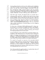
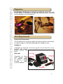
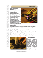
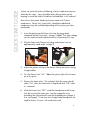
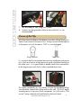
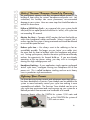
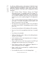
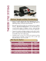
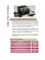
Soldering Solutions
User Manual for
Resistance-Based Soldering, Brazing &
Thermal Wirestripping Systems
www.americanbeautytools.com
1
TABLE OF CONTENTS
TABLE OF CONTENTS
2
INTRODUCTION3
INTRODUCTION TO RESISTANCE SOLDERING
4-5
Definition
4
Core Requirements
4
Advantages
5
QUICK START GUIDE
6-7
Basic Set-Up
7
DEVELOPING YOUR PROCESS
8-10
Risk of Thermal Damage Caused by Overuse10
Refining Your Process
10
SAFETY
11
TWEEZER STYLE SYSTEMS
12
PLIER STYLE SYSTEMS
13
PROBE STYLE SYSTEMS
14
WIRESTRIPPING & REFLOW SYSTEMS
15
WARRANTY AND SERVICE DETAILS
16
Company Information
American Beauty Tools are made just outside of Detroit Michigan, USA.
Ph:
1.248.280.2810
1.800.550.2510
Fax:
1.248.280.2878
Email:
[email protected]
Website:
www.americanbeautytools.com
2
INTRODUCTION
American Beauty has been a fixture in the soldering tool marketplace
since 1894. Our tools are a throw-back to a time when people took
pride in the tools they used and companies took pride in the tools
they manufactured. Today, American Beauty® tools are routinely
chosen to tackle the most challenging soldering, brazing and thermal
management applications with a diverse line of soldering irons and
stations, solder pots, resistance soldering systems and accessories.
With these types of tools, the operator plays an essential role in
achieving quality end-results, avoiding injury and ensuring a long
product lifespan. Please ensure that you take the time to read this
manual carefully. It contains all the information required to understand
how to properly set-up, operate & maintain this American Beauty
equipment. Additionally, please feel free to visit our full-service
website (www.americanbeautytools.com) for links to instructional
videos, product specifications, a technical blog, an on-line shopping
cart and much more.
For those new to Resistance Soldering/Brazing and it’s many uses,
rest assured, it is a tried and true product that offers many benefits.
American Beauty has been manufacturing, testing, and refining
their entire line-up of Resistance Soldering, Brazing, and Thermal
Wirestripping equipment for over fifty years.
As the manufacturer of the world’s largest assortment of power units,
handpieces, and related accessories, we pride ourselves in being the
leader in the design and development of resistance based soldering
equipment. All American Beauty products are manufactured using
the highest quality materials available and are assembled with great
care so they will consistently conform to our quality specifications.
This manual will provide an overview of the principles behind
Resistance Soldering, Brazing, and Thermal Wirestripping, and other
applications requiring intense localized heat. General operating
procedures as well as guidelines for model/system selection will be
covered to help make your Resistance Soldering, Brazing, or Thermal
Wirestripping experience a positive one.
If you have purchased a specific product, it’s product data sheet will
be inserted in the centerfold of this manual.
www.americanbeautytools.com
3
INTRODUCTION TO REISTANCE SOLDERING
Definition
re•sist•ance sol•der•ing- a method of soldering where the heat
to melt solder is instantaneously generated by passing an electrical
current through a resistive material.
Core Requirements
Power Unit & Footswitch
The foundation of a resistance soldering system; produces and controls
an ample supply of safe high amperage, low voltage current.
Handpiece
Completes an electrical circuit carrying the current from the source,
through the pieces
being soldered and
back.
Electrodes
Generates an instant
and
intense
level
of thermal output
as current is forced
through its highly
resistive material.
4
INTRODUCTION TO REISTANCE SOLDERING
Advantages
Smash Operational
Bottlenecks
Concentrated heat reduces
solder many times over.
Flameless process
Improve Solder Joint
Quality
Poor solder joints are often
the result of insufficient
heat throughout the joint,
creating weak spots.
Eliminate Thermal Damage
Traditional soldering
methods introduce too
much heat into surrounding
areas damaging critical
components or desoldering
of previously soldered joints.
Reduce Liability
Light-weight handpieces cool within seconds, greatly reducing the
likelihood of repetitive strain injury and virtually eliminating the burn
risk for the user.
Solder in Tight Spots
Versatile systems allow easy access to restricted areas.
Cut Down on Energy Consumption
Instant heat means you’re not paying to heat a soldering station all
day long.
Save on Maintenance and Consumables
Electrodes last twice as long as soldering tips and don’t require
constant re-wetting/tinning.
American Beauty
When
it
comes
to
Resistance
Soldering,
no other company in
the world combines the
depth of knowledge with
the breadth of product
offerings as American
Beauty Tools. We offer
the widest selection of
handpieces,
electrodes
and power units and back
our equipment with the
industry’s best warranty.
www.americanbeautytools.com
5
QUICK START GUIDE
System set-up for Resistance Soldering is fairly simple and requires
relatively few steps. Care should be taken during each step by
keeping in mind the Safety Guidelines outlined later in this manual.
Most of our Resistance Soldering Systems come with 3 basic
components: Power Unit, Footswitch, Handpiece (additional
components may be included depending on the system you have
purchased).
1. Insert the plug from the Power Unit into the piggy-back
receptacle on the Footswitch. (Image 1) Note: Our high voltage
versions feature hardwired footswitches, eliminating this step.
2. Plug the Footswitch/Power Unit plug combination into an
appropriately rated outlet. (Image 2)
3. Adjust the power setting on the Power Unit to the lowest setting
(if applicable).
4. Turn the Power Unit “On”. Note: the power light will not come
on at this point.
5. Depress the Footswitch. The indicator light for power should
come “On” when the Footswitch is depressed and “Off” when it is released.
6. With the Power Unit “Off”, install the Handpiece to the Power
Unit by inserting the taper pins into the receptacle or by
threading the ring terminals onto the threaded posts (Image 3
& 4, next page). In the case of a Single Probe Handpiece, the
Lead for Return Current will need to be used.
6
QUICK START GUIDE
7. You are ready to start using your system.
8. Systems can be operated without a footswitch but it is not
recommended.
Basics of Set-Up
All of the American Beauty Handpieces use either a Ring Terminal or
Taper Pin to connect to the power unit. Always connect the handpiece
to the power unit with the power “OFF” or unit unplugged.
Ring Terminal
Taper Pin
It is essential that the connection between the handpiece and power
unit is flush and secure at both points to avoid intermittent heating at
the solder joint. It is a good habit to double check these connections
at the beginning of each shift or after extended down-time.
The output receptacles on your power unit that the handpiece plugs
into should be treated like a plug outlet in the wall. DO NOT apply
a metal piece or strip across these receptacles, as it will result in “live
current” being released and could lead to electrical shock.
www.americanbeautytools.com
7
DEVELOPING YOUR PROCESS
The goal of your process is to establish the shortest, controllable cycle
time to achieve a quality solder joint, without causing thermal damage
to the components being soldered. To develop this process you will
need a basic understanding of how resistance soldering generates
heat and some scrap pieces for testing.
Resistance soldering systems require an electrical circuit running from
the power unit, down the handpiece and through the solder joint
itself, which is why our systems cannot be used to heat non-conductive
components
In the graphic above, the electrodes holding the soldered components
have a much higher degree of electrical resistivity than the rest of
the circuit. When electricity is forced through a resistive material,
the result is heat. Since the components being soldered have their
own unique resistive qualities, heat is also being generated within the
joint itself. The result is virtually instantaneous, intense heat that stays
largely localized to the point(s) of contact.
Therefore heat and speed at the solder joint is going to be unique to
each application, based upon system used and materials/components
soldered. Hence, the need for a ‘trial and error’ approach to process
development that will require scrap components and a few rounds of
testing.
Note: Please keep in mind, that while cleanliness of materials has
always been paramount to a quality solder joint, it takes on an
even greater importance with resistance soldering. Oxidation,
contaminants and any coatings can impede the flow of electricity and
render resistance soldering ineffectual.
8
DEVELOPING YOUR PROCESS
• Begin with a mid-range power setting.
• Ensure a good fit between the components to be soldered.
Establish contact between the electrode(s) of your handpiece and
the components. Electrodes should be as close to the solder joint
as practically possible.
• Depress the footswitch. You can often feel and hear that the
system has activated by a slight vibration in the handpiece and
buzz in the power unit. If you do not, it’s most likely that an
electrical circuit has not been established. Check connections and
cleanliness of components and electrodes.
• Hold solder at the joint so that it will begin to reflow as soon as the
temperature at the joint permits. (If solder has not flowed after 20
seconds, STOP. Allow components to cool, turn the power setting
higher and repeat.)
• Once you are satisfied with the amount of solder added to the
joint, release the footswitch and let cool. Warning: Components
will take much longer to cool than they took to heat.
• Evaluate solder joint and surrounding materials.
• Did the solder flow too quickly resulting in an unreliable solder
joint or uncontrollable application of heat? If so, turn the setting
lower and repeat as necessary until satisfied.
• Was the cycle time too slow, resulting in thermal damage to
the components and/or surrounding materials? Turn the setting
higher and repeat as necessary until satisfied.
• Ideal cycle times are typically between 3 to 8 seconds. Larger
joints or brazing will require longer cycle times. (Please pay close
attention to Risk of Thermal Damage Caused by Overuse, pg 10)
Watch our Soldering Guru tackle all sorts
of challenging jobs using our Resistance
Soldering Systems. Scan here or follow
this link.
www.youtube.com/user/SolderingGuru
www.americanbeautytools.com
9
DEVELOPING YOUR PROCESS
Risk of Thermal Damage Caused by Overuse
An ever-present concern with any resistance based system is the
buildup of heat within the system’s handpiece and power unit. Left
unchecked, this buildup can cause permanent, non-warrantied
damage to your system. Here are some steps that should be taken to
reduce this occurrence.
Follow a 50/50 Duty Cycle ~ as a general rule, your system should
idle (cool) for an equal period of time that its ‘active’, with cycle time
not exceeding 20 seconds.
Monitor the Heat ~ Operator MUST monitor the heat that builds-up
within their handpiece’s cables and handle. Warm is normal. Hot is
a clear sign that the system is being overtaxed and should be allowed
to rest and dissipate the heat.
Reduce cycle time ~ You always want to be soldering as fast as
controllably possible. The longer you are ‘active’ on a solder joint,
the more time for heat to buildup within the handpiece and power
unit. Turning up the power, shortens the active cycle time and thereby
reduces the opportunity for thermal build-up. If you are already
operating at the top power setting, you may wish to investigate
moving to a high wattage power unit.
Handpiece Stacking ~ If your application simply requires prolonged
‘active’ cycle times, investigate running two handpieces off of one
power unit. This is called handpiece stacking and can assist heavy
users in production style environments.
Refining Your Process
For those desiring further control and refinement once their process
has been developed, a Precision Timer Module can be added to the
system to more accurately control your cycle time making it more
repeatable and reliable. The Precision Timer Module can be set to
your cycle time requirement and used to power up your system for a
defined period of time accurate to a hundredth of a second.
American Beauty offers the 105PTM for systems 1,100 watts and
less, or the 105HCPTM for systems of
1,200 watts or more..
10
SAFETY
As with any soldering process, the presence of electrical current
and high temperatures are required to make the system work. Each
application should be evaluated for unique safety needs beyond
the general guidelines listed below and the appropriate training
developed.
• Most American Beauty Resistance, Brazing and Thermal
Wirestripping Systems are available in both a low voltage (110120VAC) and high voltage (220-240VAC) version. Please consult
your cord label to determine what version you have purchased
and ensure your system is properly plugged in to the appropriate
outlet.
• Always wear Personal Protective Equipment (PPE) when operating
your system. This includes safety glasses, protective gloves, and
sleeves (if necessary) to cover your body.
• The temperature of your electrodes and parts of your handpiece
can reach in excess of 900°F. Mishandling can result in a serious
burn or fire.
• Do not touch any metal parts of the handpiece while in operation.
• Do not use the unit for any application other than it’s intended
use.
• Do not leave unit unattended.
• Soldering will produce smoke. Make sure the soldering location
selected is well ventilated.
• Let the handpiece cool to room temperature prior to storage or
before changing electrodes.
• Always make sure the unit has been properly turned OFF and
unplugged when finished using or prior to moving unit.
• Never attempt to perform repair, replacement, diagnostics, or
routine maintenance while unit is plugged in.
• Repairs should only be performed by a qualified technician
familiar with the product.
• Do not modify the system or use it with damaged parts.
www.americanbeautytools.com
11
TWEEZER STYLE SYSTEMS
Features, Benefits and Other Considerations
• Family of systems ranging from those appropriate for microconnectors and PC Board work to those with enough power to
tackle large military connector and 4G antennas.
• Electrodes can be bent to allow for even better access to difficult
locations. Tip from our Soldering Guru ~ Insert the electrodes into
a vise & bend to approx. 25 degrees, reinsert, rotate and align
so that tips are at appropriate distance to match your application.
• Tweezer functionality and lighter handpieces lends itself to ‘hold in
place’ functionality during soldering operation and electrodes last
considerably longer than soldering tips.
• Available systems run from 100 to 1,800 watts, maximum working
opening between electrodes ranging from .375” to .625” and
electrode diameters from .04” to 1/8”.
Most Popular Systems
Model Name
Model #
Micro Capacity Tweezer Style
10599
Ultra-Light Capacity Tweezer Style
10501
Light Capacity Tweezer Style
10502
Standard Capacity Tweezer Style
10504
High Capacity Tweezer Style
105L7
Ultra-High Capacity Tweezer Style
105K5
12
PLIER STYLE SYSTEMS
Features, Benefits and Other Considerations
• The carbon electrodes used in these systems have a higher
intrinsic resistivity to electricity and permit more surface contact
than the steel electrodes used in tweezer systems . The result is
more intense heat and better thermal saturation, lending these
systems to tackle more demanding applications, such as semirigid coax, brazing operations and production work.
• Electrodes can be easily shaped or notched with a jewelers file or
similar tool. Tip from our Soldering Guru ~ Modify the electrode
to match the contour of the intended components surface. A little
extra time in prep results in easier soldering later.
• Available systems run from 250 to 3,000 watts, working opening
between electrodes ranging from .25” to 3” and electrode widths
from .25” to .5”.
Most Popular Systems
Model Name
Model #
Light Capacity Plier Style
10506
Standard Capacity Plier Style
10507
High Capacity Plier Style
105L5
Ultra-High Capacity Plier Style
10505
Resistance Brazing System
10557
Resistance Brazing System-High Capacity
10577
www.americanbeautytools.com
13
PROBE STYLE SYSTEMS
Features, Benefits and Other Considerations
• Probe systems require the use of a return lead to close the electrical
circuit required for resistance systems to function. When this is
feasible, single probe systems are highly desirable as they offer
instant, localized heat combined with pin-point control. Ideal for
multi-pin connectors, multiple joints along a bus-bar, and many
other challenging joints.
• Try using a conductive plate or mounting fixture for added
repeatability. Tip from our Soldering Guru ~ Depending upon
materials being soldered, the return lead does not always have
to be clamped directly on, or even near, the joint being soldered.
• Available systems run from 100 to 3,000 watts with electrodes
diameters ranging from 1/16” to ½”.
Most Popular Systems
Model Name
Model #
Ultra-Light Capacity Probe Style
10508
Light Capacity Probe Style
105L9
Standard Capacity Probe Style
10509
High Capacity Probe Style
105H9
Fixed Dual Probe Style
10535
Resistance Brazing System-Probe Style
105U9
14
WIRESTRIPPING & REFLOW SYSTEMS
Features, Benefits and Other Considerations
• Wirestripping and Reflow systems differ from the other styles of
resistance soldering systems, as these systems pass a controlled
current through a closed-loop resistive material, creating a hotformed wire that can be used to strip insulating jackets off wires
(including Teflon and other PTFE-type materials), used as a hotknife to melt and trim plastics and waxes, reflow solder balls, and
even perform some wood burning.
• Wirestripping handpieces are either tweezer style for smaller
gauge, or V-notch style for stripping the insulation on large wires
and cables.
• Stripping with heat versus a blade guarantees not to nick any
conductors.
• Available systems run from 100 to 1100 watts with a wide variety
of handpiece styles.
Most Popular Systems
Model Name
Model #
Thermal Wirestripping System - Micro Capacity
10503M
Thermal Wirestripping System - Std. Capacity
10503
Thermal Wirestripping System - High Capacity
10503X
Reflow System - Micro Capacity
105RFM
Reflow System - Standard Capacity
105RFS
Reflow System - High Capacity
105RFH
www.americanbeautytools.com
15
WARRANTY & SERVICE DETAILS
Warranty Details
American Beauty tools are warrantied to be free from defects in
material and workmanship as outlined below. No warranty is made
with respect to products which have been altered, subjected to abuse
or improperly used.
Consumable Parts - NOT COVERED
Items include such parts as Soldering Iron Tips, Desoldering Braid,
Resistance Soldering Elements and Electrodes, etc.
Serviceable Parts - 90-DAY PERIOD
Items include such parts as are Heating Elements, Thermostats, Voltage
Controllers, Cord-sets, etc. It is the customer’s responsibility to make
themselves aware of proper operating parameters, that when not
followed, can greatly reduce the life-span of this type of part.
Standard American Beauty Products - 3-YR PERIOD
These items include all American Beauty soldering tools that don’t fall
into the two categories highlighted above.
Complete warranty details can be located on our company website at
www.americanbeautytools.com/warranty
Repair Service
Eventually even the toughest soldering tools require minor repair work.
We have expanded our internal repair department and reassigned
our most experienced technicians to work on repairs. We implemented
customized software to ensure accurate and timely processing of
all returned products. Save yourself unnecessary downtime and
aggravation by taking advantage of American Beauty’s worldclass repair and refurbishment service. Contact us today to make
arrangements, or visit www.americanbeautytools.com/repair
16