1
Dupline
Bus System
Planning Aid and Product Information
February 2006 - v1.60
Dupline
Bus System
Planning Aid and Product Information
February 2006 - v1.60
Doepke
Registered Trademarks
IBM and IBM PC are registered trademarks of the International Business Machines Corporation.
Microsoft, MS-DOS and Windows® are registered trademarks, and Windows® NT, Windows® 2000
and Windows® XP are trademarks of the Microsoft Corporation.
Dupline is registered trademark of the Carlo Gavazzi Group.
Liability
All information contained in this document of Doepke Schaltgeräte GmbH & Co. KG is protected by
copyright. The reproduction and processing, altering and/or transfer against payment of such information is permissible only with the express written approval of Doepke Schaltgeräte GmbH & Co. KG.
This information is provided solely as customer information and does not constitute a binding guarantee or undertaking. It is subject to changes at any time, be it in technical content or in price/commercial terms. Binding statements can only be given following specific enquiries.
Being non-binding, no liability of any kind can be accepted for the accuracy of the information.
The use of this document is solely at your own discretion. Doepke Schaltgeräte GmbH & Co. KG
accepts no liability for any damages arising from the use of this document, in particular breakdown of
operations, loss of earnings, loss of information and data or consequential damages, except in cases
of compulsory liability, e.g. as provided for by the Product Liability Law, or in cases of premeditation,
gross negligence, absence of promised capabilities or because of infringement of fundamental contractual obligations. Compensation for infringement of fundamental contract obligations shall, however, be limited to contract-typical foreseeable damage, provided there is no premeditation or gross
negligence.
Copyright © Doepke Schaltgeräte GmbH & Co. KG 2006
February 2006 - v1.60
Dupline Planning Aid and Product Information
Doepke
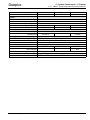
Contents
Table of Contents
Chapter 1 - Introduction
1.1
1.2
1.3
1.4
1.5
General .......................................................................................................................................... 4
About this Document...................................................................................................................... 4
Abbreviations and Terms ............................................................................................................... 4
Related Dokuments ....................................................................................................................... 6
What is Dupline?............................................................................................................................ 7
1.5.1 General ............................................................................................................................... 7
1.5.2 The Technology .................................................................................................................. 7
1.5.3 The Quality ......................................................................................................................... 7
Chapter 2 - Dupline - The Basics
2.1 System Configuration..................................................................................................................... 8
2.1.1 Overview............................................................................................................................. 8
2.1.2 Transmission Line Structure ............................................................................................... 9
2.2 Signal Transmission..................................................................................................................... 11
2.2.1 Introduction ....................................................................................................................... 11
2.2.2 Carrier Signal and Channel Addresses ............................................................................ 11
2.2.3 Addressing........................................................................................................................ 12
2.2.4 Transmission Procedure ................................................................................................... 12
2.2.4.1 Overview ............................................................................................................ 12
2.2.4.2 Control status..................................................................................................... 12
2.2.4.3 Analog measurements (AnaLink)....................................................................... 12
2.2.4.4 Counter data (time-division multiplex method)................................................... 12
2.3 Inputs and Outputs....................................................................................................................... 14
2.3.1 General ............................................................................................................................. 14
2.3.2 Address Assignment......................................................................................................... 14
2.3.3 Functions .......................................................................................................................... 14
2.3.4 Power Supply.................................................................................................................... 14
2.3.4.1 General .............................................................................................................. 14
2.3.4.2 Components with AC power supply ................................................................... 15
2.3.4.3 Components with internal DC power supply ...................................................... 15
2.3.4.4 Components with external DC power supply ..................................................... 15
2.4 Standards and Enclosure Protection............................................................................................ 17
2.4.1 Standards.......................................................................................................................... 17
2.4.2 Enclosure Protection Type................................................................................................ 17
Chapter 3 - Notes on Wiring and Installation
3.1
3.2
3.3
3.4
3.5
General Notes.............................................................................................................................. 18
Cable Recommendations............................................................................................................. 19
Cable Length and Resistance...................................................................................................... 20
Line Termination........................................................................................................................... 20
Lightning Protection ..................................................................................................................... 21
Chapter 4 - Networks and Visualisation
4.1 Networks ...................................................................................................................................... 22
Dupline Planning Aid and Product Information
February 2006 - v1.60
Page 1
Doepke
Contents
4.1.1 Overview ...........................................................................................................................22
4.1.2 Installation of RS485-Networks.........................................................................................22
4.1.3 Networks with DKG 20 / DKG 21-GSM.............................................................................22
4.2 Visualisation .................................................................................................................................24
4.2.1 Overview ...........................................................................................................................24
4.2.2 Visualising at the Channel Generator ...............................................................................24
4.2.2.1 DKG 1 / DKG 2...................................................................................................24
4.2.2.2 DKG 20 / DKG 21-GSM .....................................................................................24
4.2.3 Visualising with the DSI 1 Modbus Interface.....................................................................25
Chapter 5 - System Components
5.1 General Information .....................................................................................................................26
5.1.1 Overview ...........................................................................................................................26
5.1.2 Notes on Product Descriptions..........................................................................................26
5.2 Central Units ................................................................................................................................28
5.2.1 DKG 1/DKG 2: Channel Generators 24 VDC and 115/230 VAC resp...............................28
5.2.2 DKG 20 / DKG 21-GSM: Channel Generators..................................................................33
5.3 Inputs ...........................................................................................................................................41
5.3.1 DBM 1: Surface-Mounted Proximity Detector ...................................................................41
5.3.2 DIR 2: Infrared Remote Control ........................................................................................44
5.3.3 DLUX: Surface-Mounted Light Level Sensor ....................................................................47
5.3.4 DNP 8E: 8-Way Binary Input Board (24 VDC) ..................................................................49
5.3.5 DPM 1: Presence Detector ...............................................................................................52
5.3.6 DRD 3: Smoke and Fire Detector .....................................................................................56
5.3.7 DRT 1: Room Thermostat in Installation Housing .............................................................59
5.3.8 DRT 2: Room Thermostat with 2-line Display, 24 VDC.....................................................61
5.3.9 DSS 4R/DSS 4R-EIB: Operating Signal Sensors with Acknowledgement .......................67
5.3.10 DSS 2U/DSS 4U/DSS 8U: Flush-Mounted Operating Signal Inputs.................................70
5.3.11 DSU 1U: Flush-mounted 1-Channel Binary Signal Converter ..........................................73
5.3.12 DSU 2U: Flush-mounted 2-Channel Binary Signal Converter ..........................................75
5.3.13 DSU 8: 8-Channel Binary Signal Converter ......................................................................77
5.3.14 DTS 1: Surface-mounted Temperature Sensor.................................................................80
5.3.15 DTS 2: Temperature Sensor in Installation Housing .........................................................82
5.3.16 DTZ 4: Rail Mounted 4-Channel Pulse Counter/Hours-Run Meter ...................................84
5.3.17 DWS 1: Water Stop Sensor...............................................................................................87
5.4 Outputs.........................................................................................................................................89
5.4.1 DDM 1Rplus: 1-Way Light Scene Dimmer, DIN-Rail Mounted..........................................89
5.4.2 DDMU 1Rplus: 1-Way Light Scene Dimmer 1..10V, DIN-Rail Mounted............................93
5.4.3 DDM 2/DDM 2plus/DDMU 2/DDMU 2plus: 2-way Dimmer, DIN-Rail mounted ................97
5.4.4 DNP 8A/DPN 8A: 8-Way Binary Output Board (24 VDC) ...............................................104
5.4.5 DRO 1U: Flush-Mounted 1-Channel Shutter Control Unit ..............................................107
5.4.6 DRO 2: Rail Mounted 2-Channel Shutter Control Unit.................................................... 110
5.4.7 DRO 4b/DRO 4c: Rail Mounted 4-Channel Shutter Control Units .................................. 113
5.4.8 DSM 1U: Flush-Mounted, 1-Way Binary Relay Output ................................................... 117
5.4.9 DSM 2: 2-Way Relay Output with 4 Semiconductor Outputs, DIN-Rail Mounted ........... 119
5.4.10 DSM 4M: 4-Channel Relay Output with manual operation, DIN-Rail Mounted...............122
5.4.11 DSM 4R: 4-Way Relay Output with Acknowledge Feature, DIN-Rail Mounted ..............125
5.4.12 DSM 8: 8-Way Binary Relay Output (230VAC), DIN-Rail Mounted.................................128
5.5 Combined Inputs and Outputs....................................................................................................131
Page 2
February 2006 - v1.60
Dupline Planning Aid and Product Information
Doepke
5.6
5.7
5.8
5.9
5.10
Contents
5.5.1 DNP 4 / DPN 4: 4-Way binary Input and Output Board (24 VDC) .................................. 131
5.5.2 DSM 4E: 4-Way Binary Relay Output with 4 Semicond. Inputs, DIN-Rail ...................... 134
Components for Visual Display .................................................................................................. 137
5.6.1 DDI 2: 2-Row Text Display, 24 VDC................................................................................ 137
5.6.2 DSC 10: Touch Screen Panel 3.8“, 24 VDC .................................................................. 142
5.6.3 DSC 3: Touch Screen Panel, 24 VDC ............................................................................ 145
Interface Components................................................................................................................ 149
5.7.1 DFA-DI: Dupline Remote Actuator Interface................................................................... 149
5.7.2 DCI 1: Serial-to-Ethernet Port Server ............................................................................. 151
5.7.3 DSI 1: Dupline - Modbus - Interface ............................................................................... 155
Load and Power Supply Units.................................................................................................... 157
5.8.1 LT 500 / LT 1200: Remote Dimmer Load Modules, DIN-Rail Mounted........................... 157
5.8.2 NT 24-250 / NT 24-1300: 24 VDC – Power Supply Units, DIN-Rail Mounted ................ 160
Accessories................................................................................................................................ 163
5.9.1 DHK 1: Hand Encoder .................................................................................................... 163
5.9.2 DTG 1: Tester ................................................................................................................. 165
5.9.3 Adapters, Cables and Special Accessories .................................................................... 166
5.9.3.1 DDA 1: DCF-Antenna for DKG 20 / DKG 21-GSM .......................................... 166
5.9.3.2 Adapters and Standard Cables ........................................................................ 167
5.9.3.3 Cable for Hand Encoder DHK 1 and Tester DTG ............................................ 170
5.9.4 Installation Accessories .................................................................................................. 172
Software..................................................................................................................................... 174
5.10.1 ProLine / ProLineNG: Configuration Software for Channel Generators ......................... 174
5.10.2 Webserver: Visualisation Software ................................................................................. 175
5.10.3 DDE-Server: Visualisation in Office Applications............................................................ 178
5.10.4 DPCamp: Software for Commissioning and Interfacing in Leisure Facilities .................. 179
Chapter 6 - Notes on Project Planning
6.1 General ...................................................................................................................................... 181
6.2 Guideline for Project Planning ................................................................................................... 181
6.3 Form for Assigned Addresses.................................................................................................... 182
Chapter 7 - Examples of Circuit Diagrams
7.1 Incorporating SI Components .................................................................................................... 184
7.1.1 Link-up of Wind / Rain Detectors (SIWR/SIRW) via DSM 4E ......................................... 184
7.1.2 Link-up of Wind / Rain Detectors (SIWR/SIRW) via DSU 8............................................ 185
7.2 DRO with DC Drives .................................................................................................................. 186
7.2.1 Feed-in by one Power Supply......................................................................................... 186
7.2.2 Feed-in by two Power Supplies ...................................................................................... 187
Chapter 8 - Suggestions, Questions and Problems
8.1 FAQs .......................................................................................................................................... 188
8.1.1 General Questions.......................................................................................................... 188
8.1.2 Questions Concerning the Products ............................................................................... 189
8.1.3 Dupline and the SI Building Management System ......................................................... 189
8.1.4 Problems......................................................................................................................... 189
8.2 Contact....................................................................................................................................... 190
Index............................................................................................................................................................ I
Dupline Planning Aid and Product Information
February 2006 - v1.60
Page 3
Doepke
1 Introduction - 1.1 General
Chapter 1 Introduction
1.1 General
Building installation technology is in a state of change; no more rigid wiring systems, but a flexible central
and decentral intelligence which makes it easier for the electrical fitter to fulfil his customer’s requirements
at sensible prices.
Doepke is following this positive trend with its new product range: Dupline. This bus system combines
easy handling with the flexibility of a bus system. Due to its interference immunity and the wide range of
products it is not only suitable for inside areas but also eminently for use in outside applications such as
camping sites and yachting marinas. But also in inside applications, Dupline can show strength: easy-tohandle shutter controls, temperature supervision or also fire alarms allow an uncomplicated solution for
problems.
Outstanding characteristics of the Dupline system include its multi-faceted bus technology and the easy
installation of the bus. This allows the installer to concentrate on providing the solutions to customers‘
requirements without having to worry about the technical implementation of the automation system.
1.2 About this Document
This planning aid is intended to acquaint you with the Dupline building automation system and to enable
you to plan practical solutions. It is provided in loose-leaf form to allow for the growing product range and
possible technical improvements.
In order to ensure that this planning aid is always up to date, Doepke will be supporting you with advice
and service: make use of our telephone support line, our e-mail update service, or the information prepared for you on our website http://www.doepke.de/uk to keep yourself fully up to date.
1.3 Abbreviations and Terms
Abbreviation
Description
AC
Alternating current
AP
Surface-mounted
Configuration
Adaptation of device’s settings to the current application:
Some components as „objects“ in ProLine or devices, need settings which
determine the device’s configuration.
Dupline+
Dupline signal conductor (+)
Dupline-
Dupline signal conductor (-)
DC
Direct current
E/A
Input/Output (I/O)
General term for components of bus systems
EEPROM
Electrically-Erasable Programmable Read-Only Memory
EMC
Electromagnetic compatibility
Encoding
Assignment of the Dupline address to a component:
When encoding, the Dupline component gets an address (e.g. B5) which enables the device to exchange data with other device.
Firmware
Process or operating system:
This „software“ most often is located on fixed programmed, intelligent devices
as e.g. DKG 1. It makes basic functionality available.
Page 4
February 2006 - v1.60
Dupline Planning Aid and Product Information
Doepke
1 Introduction - 1.3 Abbreviations and Terms
Abbreviation
Description
FPROM
Flash Programmable Read-Only Memory:
Memory module, which is permanently programmed with data by applying a
voltage.
HMI
Human Machine Interface:
Previously called „Men Machine Interface („MMI“), today also called „SCADA“
(see „SCADA“).
LCD
Liquid crystal display
LED
Light emitting diode: Light emitting semiconductor diode
Modbus
Protocol for data exchange via serial interfaces; „Modbus I RTU“, the basic protocol, has been standardised by Messrs. Gould Electronics.
NPN-Transistor
Semiconductor component with np-junction for switching currents:
This design permits the switching/controlling of loads which are connected to
the supply voltage (e.g. +24VDC).
PCB
Printed Circuit Board
PNP-Transistor
Semiconductor component with pn-junction for switching currents:
This design permits the switching/controlling of loads which are connected to
neutral.
Profibus
Abbreviation for „Process Field Bus“:
This is a bus system that originally has been used in industry for cross-linking
input and output devices - also on system level. Today, this bus system is used
in various applications.
Profibus-DP
Abbreviation for „Process Field Bus - Decentralized Periphery“:
This is a special version of Profibus, tuned in reaction time on signal level.
Programming
This, in general, is the configuration (see above) of the channel generator by
means of „ProLine“ - there, objects are inserted and configured.
REG
DIN-rail mounted device (device for mounting on distribution facility)
SCADA
Supervisory Control And Data Acquisition:
Software or device that offers the possibility to display and/or to modify process
signals.
Touch Screen Panel
Touch and control panel:
Screen which enables commands to be input by directly touching the screen
surface.
UP
Flush-mounted
VAC
AC voltage
VDC
DC voltage
Dupline Planning Aid and Product Information
February 2006 - v1.60
Page 5
Doepke
1 Introduction - 1.4 Related Dokuments
1.4 Related Dokuments
Referenz
Beschreibung
[1]
ProLine
Configuration Software for the Dupline Bus System - User Manual
59 00 126
[2]
ProLineNG
Configuration Software for the Dupline Bus System - User Manual
59 00 142
[3]
Dupline
System-Katalog (Carlo Gavazzi GmbH)
CAT DUP GER
13 06/00
Page 6
February 2006 - v1.60
Dupline Planning Aid and Product Information
Doepke
1 Introduction - 1.5 What is Dupline?
1.5.1 General
1.5 What is Dupline?
1.5.1 General
Dupline is not a new bus system. This product from Messrs. Carlo Gavazzi Industri A/S (Denmark) stands
the test for many years in more than 100,000 industrial applications and has now been optimized for use
in building installation by Doepke. By observance of the absolute compatibility between the products of
Carlo Gavazzi Industri A/S and those of Doepke, you are able to fall back on a very large product range.
Ask us!
1.5.2 The Technology
Dupline is a programme of modules for transmitting signals, which can be configured to provide economic
solutions for a very wide range of applications in the industrial sector as well as in building installations.
This system for signal acquisition and remote control could also be termed as follows:
• Building installation bus
• Field bus
• Remote actuating system
• Field multiplexer
• Remote I/O system
• Remote control system
• Decentralized signal acquisition and control system
• Transmission system for monitoring and control
• etc.
The basic function of Dupline can be summed up as follows:
Input of different signals at various remote locations, transmission of these signals to different locations
and output of the signals either in the form in which they were input or in a different form. As opposed to
conventional point-to-point wiring of all signals in one system, with Dupline all signals are routed via only
two industry-standard wires.
The simplicity of Dupline’s application makes it very attractive for installers, electricians and control cabinet manufacturers, who want to achieve a reduction in manpower and cabling costs. Dupline is also the
ideal system for connecting widely branched monitoring and control signals to a central location, e.g. indicator/control boards. Such facilities and devices can range from e.g. simple push-buttons and indicator
lamps, to control programmes for PCs or touch screen panels.
With Dupline almost every building system signal or process (digital, analog, counter, level, temperature
etc.) can be connected and transmitted to any desired location.
As opposed to systems which transmit a specific number of signals from A to B, the transmission with
Dupline works fully bi-directional and the cable can be branched in many directions. A signal may be
received anywhere along these two wires and as often as necessary. At the same time, a signal can be
locked on for transmission at any desired point of the two wires.
1.5.3 The Quality
All components of the Dupline system is permanent subject to quality controls, no matter whether within
the scope of ISO 9001, CE certification or Europe standardisation, no matter whether the products are
manufactured in Denmark or Germany.
But we also know that quality can not only be described by guidelines. Therefore, many proposals and
suggestions for improvements from planners, electrical fitters and end users flow into the design and the
handling of our components.
Dupline Planning Aid and Product Information
February 2006 - v1.60
Page 7
Doepke
2 Dupline - The Basics - 2.1 System Configuration
2.1.1 Overview
Chapter 2 Dupline - The Basics
2.1 System Configuration
2.1.1 Overview
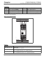
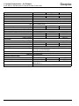
A Dupline system basically consists of four components:
Component
Symbol
Description
Two wires
A pair of wires connects all Dupline components with each
other and thus permits the signals to be relayed.
One channel generator
The channel generator provides the carrier signal on the
Dupline bus lead. This signal permits the components of
the bus to exchange data by means of the time multiplex
method.
Input modules
Input modules, or inputs for short, within a Dupline system
detect the switching status or pick up analog data and
make these available to other items connected to the bus.
Output modules
Output modules, or outputs for short, emit the signals of the
Dupline system, e.g. via relays or instruments.
Combined inputs and outputs such as e.g. the DSM 4E, provide a practical addition to the Doepke
Dupline system. But as they function like standard components they are not specifically listed here.
This chapter deals with the structure of single Dupline systems; networks consisting of single systems are
described in Chapter 4 "Networks and Visualisation" on Page 22.
Page 8
February 2006 - v1.60
Dupline Planning Aid and Product Information
Doepke
2 Dupline - The Basics - 2.1 System Configuration
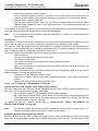
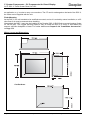
2.1.2 Transmission Line Structure
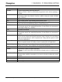
2.1.2 Transmission Line Structure
The principle of data transfer with Dupline systems means that the requirements for the mechanics and
configuration of the bus are minimal. Installation of the transmission line may be linear, star-type, ring-type
or any combination of the above.
The following diagrams illustrate the possibilities:
Linear Installation:
Star-type Installation:
With a total bus line length of approximately 10 km this type of configuration
is probably the most frequently used.
In order to calculate the total bus line
length of this type of installation it is only
necessary to add the lengths of the two
lanes.
Ring-type Installation
With ring-type installations the circle may be closed.
Dupline Planning Aid and Product Information
February 2006 - v1.60
Page 9
2 Dupline - The Basics - 2.1 System Configuration
2.1.2 Transmission Line Structure
Doepke
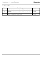
Combined Installation
With combined installations all the lengths of the individual lanes must be added together.
Note:
Page 10
Interlocked, closed rings are not allowed.
February 2006 - v1.60
Dupline Planning Aid and Product Information
Doepke
2 Dupline - The Basics - 2.2 Signal Transmission
2.2.1 Introduction
2.2 Signal Transmission
2.2.1 Introduction
Dupline is a bus system based on a time-division multiplex method. The basic idea of this method is to
record signal values at fixed times and to transmit them on only two wires, which otherwise are sent on
parallel wires („channels“).
In Dupline, this method is realised for in all 128 signal values which means, that every value is transmitted
in each cycle. Since the naming of the channels with pure numbers from 1 to 128 is difficult to understand,
an address value is assigned to each channel. Thus the signals transmitted by Dupline can be called
either „channels“ or „address values“.
Contrary to other bus systems these addresses, or channels, do not serve as a physical response to
inputs or outputs but represent a function, e.g. input and output signals. Such a function could be - to
quote the simplest example – the switching of a lamp. This function is then carried out simply by the configuration of the input and the output with precisely this address.
If the input now switches the signal on (i.e. it activates the function), the output will react accordingly.
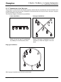
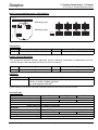
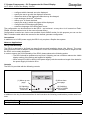
2.2.2 Carrier Signal and Channel Addresses
Inputs and outputs require a „transportation“, so called „carrier signal“, for transmission of signals; this one
is generated by the channel generator (DKG 1).
This carrier signal consists of a synchronising signal of 8 ms length and up to 128 channel pulses each
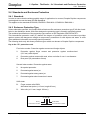
with a length of 1 ms. The following diagram illustrates the signal sequence and the address assignment:
Channel
A1
(1 ms)
Channel
A2
(1 ms)
Channel
P8
(1 ms)
Synchronisation
Signal
(8 ms)
Channel
A1
(1 ms)
The channel pulse following immediately after the synchronising signal is always assigned to channel
address A1. In general, the cycle time Tcyc with n channels can be expressed by the following equation:
Tcyc = 8 ms + 1 ms x nchannels
As the figure above illustrates, a definite address is assigned to each channel; the addressing of these
channels is in groups (A to P) of 8 channels each (1 to 8). With a maximum configuration of 128 channels,
the first channel has the designation A1 and the last the designation P8.
With the aid of the “ProLine“ configuration software, the number of channels within the 16 to 128 range
can be set up, in steps of 8 channels, so that depending upon the channel number the following
addresses and cycle times result:
Number of Channels
Addresses
Cycle Time
16
A1..B8
24 ms
32
A1..D8
40 ms
64
A1..H8
72 ms
128
A1..P8
136 ms
For further information on the channel generator and its functions see Chapter 5.2.1 "DKG 1/DKG 2:
Channel Generators 24 VDC and 115/230 VAC resp." on Page 28.
Dupline Planning Aid and Product Information
February 2006 - v1.60
Page 11
Doepke
2 Dupline - The Basics - 2.2 Signal Transmission
2.2.3 Addressing
2.2.3 Addressing
As already mentioned, the addressing does not serve to physically activate input or output devices so that
it is possible – and even desirable – to assign identical addresses to input and output devices.
If an input and an output have the same address, then the input signal is transmitted directly to the output
by a channel generator which has been configured correspondingly. The same address can also be
assigned to several input devices so that they act as an „Or“ function. If several outputs have the same
address as an input, the input signal will act on all outputs. It is therefore possible for one input signal to
be output at several locations simultaneously.
The following diagram illustrates the input of two signals at address A3 with an output at two devices:
OR
A3
A3
“1”
A3
“0”
A3
“1”
“1”
2.2.4 Transmission Procedure
2.2.4.1 Overview
On the Dupline bus there are three different transmission formats for relaying input data:
• Control status (ON/OFF)
• Counter values
• Analog measurements by the AnaLink method
This chapter shall give you an insight into the details of the transmission methods, that however goes far
beyond the absolute necessary knowledge about Dupline.
2.2.4.2 Control status
This standard transmission format is employed in the majority of standard inputs and outputs. It represents, for example, the status of a switch, i.e. “OFF“ or “ON“ and uses exactly one freely programmable
channel. Such control states are also called “binary coded values“.
2.2.4.3 Analog measurements (AnaLink)
Analog measurements can be transmitted as AnaLink or as BCD data (see following chapter).
With the AnaLink procedure the data are transmitted serially via only one freely eligible channel or
address, e.g. "P5". In this process the states ("0" or "1") are added up over a total of 256 cycles. This
means that, in an extreme case, nothing but "0" values equate to an analog value of 0%, while nothing but
"1"s correspond to 100%. The absolute value will always depend upon the measuring range of the sensor.
Because of the serial transfer this procedure is primarily suitable for the transfer of slowly graduating
measurements.
2.2.4.4 Counter data (time-division multiplex method)
In the transfer of counter/meter data a distinction should be made between the transfer format and the
transfer mode of the data:
The transfer format for counter/meter data is normally by means of the so-called BCD representation.
This representation is based on decimal points (power of ten) in which the values 0 to 9 are each
expressed by 4 bits. The following diagram illustrates the conversion of data into BCD representation and
Page 12
February 2006 - v1.60
Dupline Planning Aid and Product Information
Doepke
2 Dupline - The Basics - 2.2 Signal Transmission
2.2.4 Transmission Procedure
of BCD into decimal format:
BCD
Decimal
Decimal
0101
1001
1*1 = 1
0*2 = 0
1*4 = 4
0*8 = 0
Sum: 5
1*1 = 1
0*2 = 0
0*4 = 0
1*8 = 8
Sum: 9
BCD
7584 :8 rem. :4 rem. :2 rem.
9*1 = 9
5*10 = 50
0
1
0
0
4
0
5
7
1
0
1
1
0
0
1
3
Sum: 59
0
0
0
1
0
0
1
1
0111 0101 1000 0100
The number of BCD places used (and thereby the number of Dupline channels used) generally depends
upon the range of the input channels. Thus the DTZ 4 pulse counter (see Chapter 5.3.16 "DTZ 4: Rail
Mounted 4-Channel Pulse Counter/Hours-Run Meter" on Page 84) can, for example, be configured for
ranges up to 99, up to 9,999 or up to 99,999,999, thus requiring up to four channel groups for the transfer.
If you wanted to transfer several data in BCD format, the total number of available Dupline channels
would soon be exhausted. For this reason an additional transfer mode was introduced: the time-division
multiplex method. This procedure permits the transmission of data from several independent channels via
the same channels.
The selection of the counter/meter readings to be transmitted is carried out with an address mechanism
via the channels B2 to B8: the channel generator writes a bit sample to these addresses which corresponds to that set of the input channel. If the input module recognizes "its" address, it makes the appropriate counter/meter reading available on the configured channels of the bus.
The current firmware (up to version 1.03) of the channel generators supports 16 of these multiplex channels (addressed via channels A1 to A4). Generators from version 3.0 on will have addressing via channels B2 to B8 implemented and will thus be able to serve up to 128 device channels.
Dupline Planning Aid and Product Information
February 2006 - v1.60
Page 13
2 Dupline - The Basics - 2.3 Inputs and Outputs
2.3.1 General
Doepke
2.3 Inputs and Outputs
2.3.1 General
Inputs and outputs are devices with at least one channel which are connected in parallel via the Dupline
net. They can be divided into two categories: those with their own power supply and those without.
Devices with their own power supply should be used wherever possible, because they do not use the
Dupline signal as their source of power and thus increase the maximum transmission distance of the
whole system.
Devices without their own power supply are supplied directly by the Dupline net. This type of input and
output is designed for decentralized measurement acquisition and signal output at locations where no
external power supply is available. These devices act as a load on the Dupline bus so that the maximum
transmission distance is reduced.
Generally speaking, the maximum allowed distance between the sensors (e.g. contacts, measuring
devices) and the input devices is dependent upon the environment; in a commercial or business environment such as e.g. an office block, the distance at the input side can be up to 12 m. But in an industrial
environment the length of a cable at the input end may not exceed 3 m.
2.3.2 Address Assignment
A Dupline component may have one or more channels depending upon its equipment. Thus it is possible
e.g. for an output also to have input channels for return communication (DSM 4R).
The channel addresses must be allocated to the devices with the aid of the hand encoder (DHK 1); the
addresses themselves can be freely selected. Unused channels should always remain uncoded, e.g. they
should not be assigned an address and any previously assigned addresses should be deleted.
In the case of outputs with digital signals the hand encoder also generally permits configuration of the output status if a system defect occurs (e.g. cable break).
For information about the hand encoder, see Chapter 5.9.1 "DHK 1: Hand Encoder" on Page 163.
2.3.3 Functions
The function range of inputs and outputs depends only partly upon their hardware equipment. It is the
implementation of the relevant item in the channel generator, or in the ProLine configuration software,
which is the decisive factor.
The simplest example for different functions are the items “push-button function“ and “touch contact function“ both of which are based on input signals from simple buttons. In the case of the push-button function
the relevant channel is only active for as long as the button is pressed – in the case of the touch contact
function the signal remains permanently set upon one actuation of the button.
It is also possible, for example, to assign certain types of operational behaviour to a shutter control when
the button is pressed (Start – Stop – Reverse).
It is for this reason that the description of the Dupline components goes into very few, if any, details in
respect of their „logic“ function.
2.3.4 Power Supply
2.3.4.1 General
Dupline signal conductors are always operated free of potential, i.e. without connection to earth potential
or to the potential of external power supply sources.
The types of connections for different module types are explained below.
Page 14
February 2006 - v1.60
Dupline Planning Aid and Product Information
Doepke
2 Dupline - The Basics - 2.3 Inputs and Outputs
2.3.4 Power Supply
2.3.4.2 Components with AC power supply
Components which operate with AC voltage always have their own separate connections for their supply.
It must, of course, be ensured that the correct operating voltage is applied.
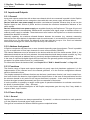
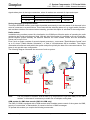
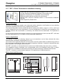
2.3.4.3 Components with internal DC power supply
In the case of components which are supplied by the Dupline bus signal, the Dupline signal conductor (-)
has to be utilized for supplying e.g. switching contacts (see DSS 4U).
In so doing it should be ensured, however, that the distance between the connection to the neutral conductor and the component is not too long, as shown in following figure:
Right
Caution!
Wrong
Lines should be kept identically long: therefore, even if you only need to use the signal
conductor (-), always install the signal conductor (+) as well. Different line lengths can
cause transmission faults.
Supplying power to switching contacts by the Dupline signal conductor (+) results in
the termination of the data transfer and is therefore not permissible.
2.3.4.4 Components with external DC power supply
As Dupline is a bus system which is separated from potential, there should basically be no connection
established between external power supplies and the bus conductors.
An exception to this rule is the wiring of the input and output boards DNP 8A, DNP 4, etc. In order to prevent equalising currents from occurring, the neutral conductor of the power supply must in these cases be
connected to the Dupline signal conductor (-).
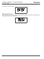
Connecting the supply voltage
If the device has been provided with a separate neutral input connection for the power supply, then this
must be used. If no neutral input is provided, the negative pole of the supply voltage must be connected
directly to the terminal of the Dupline signal conductor (-).
Right
Note:
Wrong
The power supply for such a component has to be installed direct neighbourhood of the
component. Several components which are locally distributed, e.g. in sub-ordinate
distribution cabinets, must not be supplied by the same power supply.
Connecting switching contacts
If the switching inputs and outputs of the components need to be connected to 0 VDC, then only the neu-
Dupline Planning Aid and Product Information
February 2006 - v1.60
Page 15
Doepke
2 Dupline - The Basics - 2.3 Inputs and Outputs
2.3.4 Power Supply
tral conductor of the external power supply may be used for this purpose.
Right
Wrong
Hidden connection to earth
When establishing the power supply care must be taken that no hidden connections are created between
the Dupline neutral and the earth potential.
Right
Page 16
February 2006 - v1.60
Wrong
Dupline Planning Aid and Product Information
Doepke
2 Dupline - The Basics - 2.4 Standards and Enclosure Protection
2.4.1 Standards
2.4 Standards and Enclosure Protection
2.4.1 Standards
In order to ensure that the widest possible range of applications is covered, Doepke Dupline components
are designed to meet the latest IEC/EN Standards.
This applies to the standards IEC60669, EN55022 / EN6100-6-3, EN55024 / EN61006-1.
2.4.2 Enclosure Protection Type
Unless otherwise specified, the Doepke DIN-rail devices offer enclosure protection type IP 40 after installation in the distribution board. With other designs the protection type is normally specifically stated.
The technical specifications of the protection type conform to IEC Regulation 529 VDE 0470T1.
This international protection code (IP) defines the degree of protection which the enclosure provides
against contact with dangerous voltage at components, penetration of solid objects and water. A suffix
gives additional information concerning special protection.
The following deals only with those protection types which are relevant to Doepke Dupline components.
Key to the “IP“ protection code
First index number: Protection against contact and foreign objects
2:
Protection against finger contact and protection against medium-sized
(12.5 mm) solid objects
4:
Protection against contact with tools, wires or similar of over 1 mm diameter
6:
Dust-proof (no penetration of dust)
Second index number: Protection against water
0:
No special protection
5:
Protected against water jet
6:
Protected against strong water jet
7:
Protected against short immersion in water
Suffix letter
B:
Finger-contact safe VBG4
Articulated test probe (ø 12 mm, length 80 mm)
D:
Wire safe (ø 1.0 mm, length 100 mm)
IP 40 B
IP key
First index number
Dupline Planning Aid and Product Information
Suffix letter
Second index number
February 2006 - v1.60
Page 17
Doepke
2 Dupline - The Basics - 3.1 General Notes
Chapter 3 Notes on Wiring and Installation
3.1 General Notes
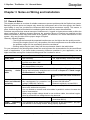
This chapter provides an overview of suitable measures to prevent problems with the Dupline bus system.
Basically, because inputs and outputs only detect the pulse-pause ratio of the bus signals, the interference liability is very low, provided the influences effect both signal conductors equally. This means, in
effect, that both signal wires should be installed together and have the same characteristics.
Problems may arise when external sources of interference in “rugged“ environments are able to effect the
signal conductors in different degrees. Because the operative ranges of Dupline are manifold and the
influence quantities, which may have effects on the system, are unknown, we - as the manufacturer of the
system - only can give hints for the proper usage of Dupline.
Generally, following applies:
• The longer the lines and the expected interferences are, the higher the wire quality must be.
• On large line lengths (from 3 km), the position of the bus components must be observed and
the possible usage of a line termination should be considered.
• Existing cables may be used if they fulfil the requirements listed in the table below.
For your assistance, the following table shows the most important line characteristics for the two different
areas of applications. If you have doubts concerning influence quantities in your application, use the
higher demands coming from industrial buildings and don’t hesitate to ask us.
Domestic buildings
Industrial buildings
Cable twist
Not necessary.
Yes, approximately 5 times per meter.
Shielding
Only when installed near to consumers with more than 1 kW.
Yes.
The shielding must have an earth wire resistance of less than 2 Ohm and may
only be earthed at one point.
Cross-section,
capacity,
resistance
You will find cable recommendations in Chapter 3.2 on Page 19. Reference
figures and calculation examples can be found in Chapter 3.3 "Cable Length
and Resistance" on Page 20.
Use only cable with same characteristics.
Insulation
resistance and dielectric
resistivity
The insulation resistance should meet
the requirements for protective low
voltage (VDE0100, Part 410).
Multicore cables
The usage of such cables is uncritical in respect to Dupline. All unused wires
have to be earthed at one point
It is not allowed to connect multi-wire cables in parallel in order to increase the
size of cross-section.
When using multiple voltage levels in one multicore cable, the national regulations for protective low voltage have to be observed.
Cable routing
Not critical.
Cable
branching
and terminals
The resistance of the clamp terminals should be as low as possible - pay special attention to the clamp contact’ being properly tightened.
Page 18
February 2006 - v1.60
Insulation resistance:
at least 100,000 kOhm(1)
Dielectric resistivity: at least 500 V
Do not install near to power cables
(more than 500 V).
Dupline Planning Aid and Product Information
Doepke
3 Notes on Wiring and Installation - 3.2 Cable Recommendations
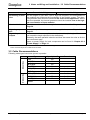
Domestic buildings
Industrial buildings
Positioning of modules
On line lengths of more than 3 km or high line resistance, the arrangement of
the modules may influence the functionality of the Dupline system. The channels generator then should be located in the centre of the application. Where
this is not possible, the channel generator should be installed near to the highest concentration of input modules.
Line termination
Should be considered on line length of more than 3 km. See Chapter 3.4 on
Page 20.
Lightning
tion
protec-
Has to be provided always on outdoor applications; see Chapter 3.5 on
Page 21.
Signal inputs and
outputs
Put sensors as close as possible to the input modules (the length of lines must
not exceed the length specified in the data sheet).
Generally, the same parasitic induction and thus also same the rules as for the
bus conductors apply.
Notes on power supply for local components can be found in Chapter 2.3.4
"Power Supply" on Page 14.
(1) Measured with a test voltage of at least 500 V. If the resistance of existing installations is less than 1000 kOhm, all junction
boxes and terminal points of cables must be tested.
3.2 Cable Recommendations
Following cable types have been proven in practise:
Indoor Use
Type
Capacity in nF
Remark
J-YY
100
J-Y(ST)Y
100
JE-Y(ST)Y
100
J2Y(ST)Y
52
RD-Y(ST)Y
100
flexible
RE-2x(ST)Ymb
60
flexible
A-2Y(L)2Y
55
flexible
A-2YF(L)2Y
55
flexible
Outdoor Use
NYM-O
NYY-O
Dupline Planning Aid and Product Information
February 2006 - v1.60
Page 19
Doepke
2 Dupline - The Basics - 3.3 Cable Length and Resistance
3.3 Cable Length and Resistance
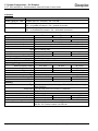
Even if the use of very different cable types hardly causes problems in practise, the following cross-section and capacity values on given length must be observed:
Maximum length(1)
Min. cross-section / diameter
Max. capacity
up to 1000 m
0.6 mm ∅
100 nF/km
1000 m ... 3000 m
0.8 mm ∅
75 nF/km
3000 m ... 5000 m
1 mm²
60 nF/km
more than 5000 m
1.5 mm²
55 nF/km
(1) This is the distance between channel generator and the outermost lying component which is supplied with voltage by the bus
signal.
For exact determination of the allowed length it has to be considered that the voltage drop for the outermost lying components must not go beyond 2 V. This voltage drop depends on following characteristics:
1. the specific loop resistance of the line;
2. the distance between channel generator and the outermost lying component;
3. the maximum current.
An example:
You are using a standard cable with a loop resistance of 120 Ohm/km. The local components you’re going
to employ have an overall power consumption of 5 mA, which approximately corresponds to 50 pieces of
the operating signal input DSS 4U (you will find the power consumption of each module in the data sheet
or in our calculation scheme).
Assuming that all components are located at the outermost end of the bus conductor, the maximum line
length can be calculated as follows (where „S“ is the value for the loop resistance):
UI = ---------S⋅l
2V
l = ------------------------------------ = 3.33 km
Ω
120 ------- ⋅ 5 mA
km
Thus, the maximum line length (l) is 3.3 km.
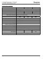
3.4 Line Termination
With longer distances (> 1.5 km) between channel generator and line terminals there is a danger of signal
reflections occurring which adversely effect the transmission. In such cases it is advisable to fit terminal
resistors at both line terminals. The line termination should be arranged as illustrated below:
Dupline+
Dupline-
Resistor
150 Ohm
0.3 W
Resistor
4,7k..22kOhm
0.3 W
Diode
2V7
0.5 W
DM_LTerm/A
150 nF
50 V
The line termination is also available separately as a DIN-rail mounted device (DT 01, 37 501 006).
Page 20
February 2006 - v1.60
Dupline Planning Aid and Product Information
Doepke
3 Notes on Wiring and Installation - 3.5 Lightning Protection
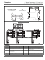
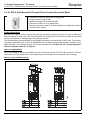
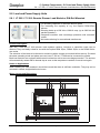
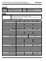
3.5 Lightning Protection
Dupline systems which could be exposed to lightning strikes should be provided with suitable lightning
protection. This applies especially to aerial lines and lines installed outside of buildings.
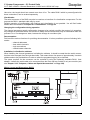
For an entire protection it is to observe, that not only the Dupline bus is protected, but also the distribution
voltage lines. Following devices then are necessary:
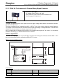
Component / Description
Manufacturer
Module
Socket
Protection of the Dupline bus
Phoenix Contact
PT 1x2 12DC-ST
PT 2x1-BE(1)
PT 2x1-BE-F(2)
Protection of 24 VDC supply inputs
Phoenix Contact
PT 2-PE/S-24AC-ST
PT-BE/FM
Protection of 230 VAC supply inputs
Doepke
RGS 1 EM
RGS BE
(1) Use this socket to apply an available shielding grounded at one end.
(2) Use this socket to apply an available shielding without grounding.
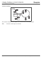
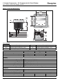
Following figure shows a connection example using the shutter control unit DRO 2 (see also
Chapter 5.4.6 "DRO 2: Rail Mounted 2-Channel Shutter Control Unit" on Page 110):
Dupline Planning Aid and Product Information
February 2006 - v1.60
Page 21
Doepke
4 Networks and Visualisation - 4.1 Networks
4.1.1 Overview
Chapter 4 Networks and Visualisation
4.1 Networks
4.1.1 Overview
The use of Dupline in large buildings or commercial installations may result in requirements exceeding the
128 channels made available by a single system. Frequently it will be possible to use several Dupline systems which work independently of each other. However, if data are to be exchanged between the systems
then interlinking is unavoidable.
4.1.2 Installation of RS485-Networks
When setting up a RS485 network with DKG 1, DKG 2, DKG 20 and DKG 21-GSM please note the following points:
• A linear layout is essential: running continuously - not radially - from DKG to DKG.
• Use only twin-core, shielded cabling; the shielding must reach all bus members. The crosssection of the cabling should be at least 0.8 mm.
• The shielding should be low-impedance connected to earth potential.
• The maximum cable length from the first to the last DKG is limited to 1000 m at max.
115,000 baud.
• You should provide a termination at the first and the last bus member (in the case of
DKG 20/DKG 21 by inserting jumper wires or, with DKG 1/DKG 2, by inserting terminating
resistors).
• It is recommended that you install all DKGs of a network at one location and thus benefit
from the advantage Dupline has over the RS485 network: the long cable lengths.
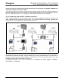
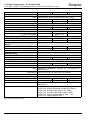
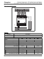
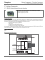
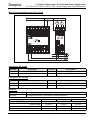
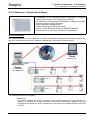
4.1.3 Networks with DKG 20 / DKG 21-GSM
The new generation of channel generators (DKG 20 / DKG 21-GSM) have been equipped with an
enhanced modbus interface offering the following advantages:
• Up to 32 channel generators can be linked to form a network;
• Interface converters are no longer required (RS485 connection is direct at the DKG);
• Configuration of all network members is via the PC connected to the master - in addition, the
DCI 2 allows remote configuration (see Chapter 5.7.2 on Page 151);
• Automatic data transfer by the channel generator configured as master, i.e. a PC or touch
screen is no longer required;
• Easy access to data of other channel generators by means of external references;
• Visualising is possible at every DKG (with some qualifications; see Chapter 4.2
"Visualisation" on Page 24);
• Synchronisation of clocks of all DKGs via the master in the network.
When setting up such a network please note - in addition to the points in Chapter 4.1.2 "Installation of
RS485-Networks" on Page 22 - the following:
• Allocation of device addresses to the slaves should start with "1" and be consecutive; i.e.
gaps in the numbering are to be avoided as these may cause delays in communication.
• If a DCF and / or GSM antenna is to be connected to the master, it is important to select the
correct positioning. Such antenna may normally not be fitted in the distribution box.
For details on installation and operation refer to the operating instructions for the DKG 20/DKG 21-GSM
and to Chapter 5.2.2 "DKG 20 / DKG 21-GSM: Channel Generators" on Page 33. The following illustration shows the layout of a modbus network with DKG 20 and DKG 21-GSM:
Page 22
February 2006 - v1.60
Dupline Planning Aid and Product Information
Doepke
4 Networks and Visualisation - 4.1 Networks
4.1.3 Networks with DKG 20 / DKG 21-GSM
Please note that the visualisation at several PCs or touch panels is a functionality of the visualising software and hardware.
Dupline Planning Aid and Product Information
February 2006 - v1.60
Page 23
Doepke
4 Networks and Visualisation - 4.2 Visualisation
4.2.1 Overview
4.2 Visualisation
4.2.1 Overview
Dupline offers numerous possibilities of visualising: the open modbus protocol permits the linking of the
most diverse display devices (HMI or SCADA) from PC to touch screen.
There are two basic ways of linking:
1. Directly at the serial port of the channel generator, or
2. Via the DSI 1 modbus interface.
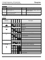
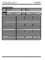
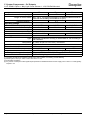
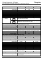
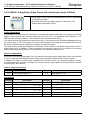
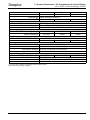
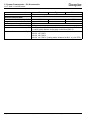
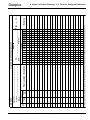
The following table illustrates which functions in respect of visualisation are available with the individual
system configurations:
System with two DKG 1/DKG 2
−
−
Modbus Network DKG 1/DKG 2
Modbus Network DKG 20/DKG 21
−
Setpoint Values
(read/write)
Switching Times
(read/write)
One DKG 20/DKG 21-GSM
Counter Values
(read-only)
−
AnaLink Values
(read-only)
−
Channel Switch Status
(read/write)
Switching Times
(read/write)
One DKG 1/DKG 2
via DSI 1
Setpoint Values
(read/write)
Counter Values
(read-only)
AnaLink Values
(read-only)
Channel Switch Status
(read/write)
via DKG
−
−
−
−
−
−
−
−
−
−
−
−
−
−
−
−
−
−
−
Detailed information on networks in provided in Chapter 4.1 "Networks" on Page 22 above.
Note:
If, for example, you want to employ several touch screens, which are to have access to the
same data records, then this can be accomplished within one network by using several
DSI 1s.
4.2.2 Visualising at the Channel Generator
4.2.2.1 DKG 1 / DKG 2
The first generation of channel generators permits connection of a visualising component not only locally
at the device but also within the network - but not at one and the same time.
Within the network the visualising component must adopt the function of the modbus master. The master
has the task of exchanging the data between the other members; this also means that should there be a
failure of the visualising component, then the data exchange will also stop. This data exchange has normally to be programmed - either via scripts on the DSC 3 touch screen, or via scripts or HLLs in software
components.
4.2.2.2 DKG 20 / DKG 21-GSM
The new generation of channel generators provides the option of reaching the data of all other network
members via the channel generator which functions as the Modbus master.
If the visualising component is connected to one of the slaves, the data of the other network members can
Page 24
February 2006 - v1.60
Dupline Planning Aid and Product Information
Doepke
4 Networks and Visualisation - 4.2 Visualisation
4.2.3 Visualising with the DSI 1 Modbus Interface
normally be read but not written. Both options are illustrated in the diagram on Page 22 in Chapter 4.1.3
"Networks with DKG 20 / DKG 21-GSM".
It should be pointed out that, when using the solution with the DKG 20 and DKG 21-GSM, a breakdown of
the visualising component would not impair the data transfer between the channel generators; and, furthermore, additional functions, e.g. changing of set-point and switching time, are available.
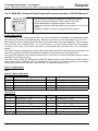
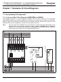
4.2.3 Visualising with the DSI 1 Modbus Interface
When employing the DSI 1 for visualising it is basically immaterial whether this takes place within a network or which channel generators are being used. You have the possibility of operating practically any
number of DSI 1s on a Dupline bus (see illustration below left).
The right-hand illustration shows the complete visualisation in a network consisting of connected DKG 1
and/or DKG 2. Because the serial ports are already in use here, visualisation can be via the DSI 1s,
whereby the latter must be assigned different slave addresses. This has the advantage that the data
exchange between DKGs takes place automatically.
For detailed information on the DSI 1 please refer to Chapter 5.7.2 "DSI 1: Dupline - Modbus Schnittstelle" on Page 148.
Dupline Planning Aid and Product Information
February 2006 - v1.60
Page 25
Doepke
5 System Components - 5.1 General Information
5.1.1 Overview
Chapter 5 System Components
5.1 General Information
5.1.1 Overview
In the following chapters the available system components are introduced and their technical characteristics described in detail.
The components are subdivided into the following groups and chapters respectively:
Central Units ................................................... Chapter 5.2 .......................................................... Page 28
These are channel generators which constitute the necessary component of any Dupline
system.
Inputs............................................................... Chapter 5.3 .......................................................... Page 41
This group encompasses all devices which capture data and transmit them to the Dupline bus
for processing. These also include e.g. sensors.
Outputs............................................................ Chapter 5.4 .......................................................... Page 89
These components output the data, e.g. 24 VDC or 230 VAC switching signals. Also included
are special devices such as shutter controls and dimmers.
Combined Inputs and Outputs...................... Chapter 5.5 ........................................................ Page 131
Components which both input and output signals can be found in this chapter. This also
includes, for example, the DSM 4E.
Components for Visual Display .................... Chapter 5.6 ........................................................ Page 137
Here you will find modules which assist in displaying the data and status of a system. This
includes e.g. the DDI 2 text display.
Interface Components ................................... Chapter 5.7 ........................................................ Page 149
This chapter contains a list of those devices which can be used for communication with other
systems, such as e.g. the DSI 1.
Load and Power Supply Units....................... Chapter 5.8 ........................................................ Page 157
Accessories .................................................... Chapter 5.9 ........................................................ Page 163
Here you will find encoding and test equipment, cables and other accessories.
Software .......................................................... Chapter 5.10 ...................................................... Page 174
Here you will find the “ProLine“ configuration software and further visualisation software.
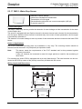
5.1.2 Notes on Product Descriptions
The description of every component normally includes the following sub-sections:
Characteristics
Here you will find a short summary of the most significant characteristics.
Product Description
This section provides a detailed description of the product and its characteristics.
Application Information
This section generally includes a connection diagram, or an example thereof, and gives information on the
configuration and employment of the component.
Page 26
February 2006 - v1.60
Dupline Planning Aid and Product Information
Doepke
5 System Components - 5.1 General Information
5.1.2 Notes on Product Descriptions
Important notes on planning and applications are also contained in this section.
Dupline channel allocation
If provided, a table shows the assignment and function of the available Dupline channels (addresses).
With the aid of the DHK 1 hand encoder any addresses can be assigned to these channels. A component
normally has 8 channels to which one channel group is assigned (e.g. group “A“). Should some of these
channels not have a function, then all channels should be assigned a single address and those without a
function explicitly no address.
Connections
In addition to the connection diagram, the table for the connections shows in a clear and easily understood manner the existing terminals and connecting lines.
Indicators
If components are equipped with indicators, their function is described under this heading.
Technical data
Any data relevant to the components are specified here. In addition to the order references of the component itself, any optical accessories and repeat order data are listed.
Dupline
Here the relevant data of the module in respect of the Dupline bus connection are listed, e.g.:
Current input: The current requirements of the device which are covered by the Dupline bus.
Input channels: The number of channels or addresses on the Dupline bus which supplies the
module with data.
Output channels: The number of channels or addresses on the Dupline bus from which the
module receives data and which it then outputs.
General technical data
Here you will find data of a general nature.
Ambient temperature: It is necessary to keep within this temperature range in order to ensure
the proper functioning of the device. In respect of the Storage temperature, for which no
details are specified, it may safely be assumed that this covers a range approximately ±20°C
larger than that of the ambient temperature.
Atmospheric humidity: This specification always assumes in the case of DIN-rail devices that
they are not exposed to dew; condensation can, under certain circumstances, render the
device unserviceable.
Enclosure protection type / Standards: Here the standards applicable to the device are listed.
In the case of DIN-rail devices the enclosure protection type refers only to the status after
connection in the distribution board.
Note:
If not mentioned differently, the component described has been designed for usage within
buildings.
Dupline Planning Aid and Product Information
February 2006 - v1.60
Page 27
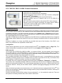
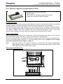
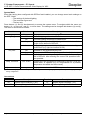
5 System Components - 5.2 Central Units
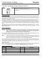
5.2.1 DKG 1/DKG 2: Channel Generators 24 VDC and 115/230 VAC resp.
Doepke
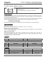
5.2 Central Units
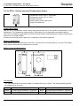
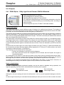
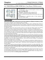
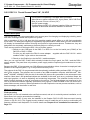
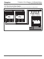
5.2.1 DKG 1/DKG 2: Channel Generators 24 VDC and 115/230 VAC resp.
• Generator for up to 128 channels
• LCD-display for real-time clock and control functions
• Channel characteristics, time functions and logic functions
configurable with “ProLine“ PC-software
• Operating voltage 24 VDC (DKG 1) and 115/230 VAC (DKG 2)
resp.
Product Description
The DKG 1 and DKG 2 channel generators are intelligent, configurable central units which generate the
Dupline carrier signal for 128 channels and are therefore the necessary central units for every system.
They differ only in their supply voltage: the DKG 1 requires a 24 VDC voltage, while the DKG 2 can be
connected directly to the AC supply net (115/230 VAC).
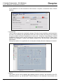
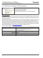
The graphic configuration software “ProLine“, which can be run on Windows® 95/98/NT/2000, permits
easy implementation of the control functions.
The channel generators offer a multitude of functions, some of which are listed below:
Different channel types
The channel generators support existing inputs and outputs in the form of channel types. These are configured by use of ProLine and can be combined as desired. The following „items“ are currently available
for selection:
• Push-buttons
• Touch contacts
• Timer with delay feature
• Time switch with 4 switch on and off times
• Central control
• Analog sensors (measurements sensors, light-, wind- and temperature sensors)
• Proximity detectors with time extension
• ISA, fire, water and intruder alarm systems (make and break contacts, acknowledgement,
reset, lamp check and audio-alarm signal)
• Shutter control and central shutter control
Logic connectives
The channel generators permit up to 64 logic combinations to be programmed with the following operators:
• AND / OR / XOR (Exclusive Or)
• Rising/Falling flank
• Disabling of operators.
In addition to the 128 Dupline channels, also 32 internal markers from W1 up to Z8 may be used.
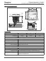
LC-Display
The back-lit, 4-digit LCD-display shows all relevant information concerning the device which can be
changed by use of the control buttons. The time clock is displayed as a standard feature; in the event of
an error, an error code will appear.
Time clock
The time of the integrated real-time clock is used in the sequencing programme and is also shown on the
Page 28
February 2006 - v1.60
Dupline Planning Aid and Product Information
Doepke
5 System Components - 5.2 Central Units
5.2.1 DKG 1/DKG 2: Channel Generators 24 VDC and 115/230 VAC resp.
LCD display. It incorporates time of day, date, day of the week and year, and can be set either via the control buttons or by means of ProLine.
Serial interface
On the one hand the interface enables the DKG to be connected to the PC in order to carry out the configuration with the ProLine software, and on the other it serves to couple two Dupline bus systems for the
purpose of data exchange and in order to increase the number of channels.
Power failure back-up
In the event of the operating voltage supply failing, the real-time clock will continue to be powered by a
condenser of sufficient capacity to ensure that at normal ambient temperatures the date and time of day
will continue to run internally for approximately 5 days. To provide back-up for longer outages, an external
9 VDC power supply needs to be connected. The configured sequencing programme is permanently
stored in a FPROM immediately after downloading to the DKG.
Watchdog (Alarm) function
The channel generators are equipped with a so-called "watchdog" output which displays the status of the
bus. When the system is operating properly the transistor will be blocking, in the event of a bus signal fault
or the power supply failing it will connect.
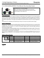
Notes on Applications
For detailed information on applications refer to the operating instructions of the channel generator and
the “ProLine“ configuration software. The latter offers complete menu-guided operation for ease of use.
Number of channel addresses
Reducing the number of channels will speed-up the configuration time and the maximum cycle time on
the Dupline bus (see also Chapter 2.2 "Signal Transmission" on Page 11).
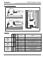
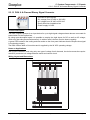
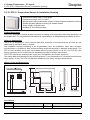
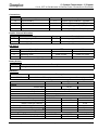
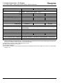
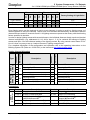
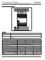
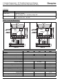
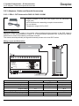
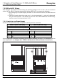
Connection between DKG and PC
The connection between the DKG and a PC for configuration with ProLine preferably should be done by
means of the optionally available interface cable DKK 1. In case of using a self-made cable, the maximum
length of 10 m should not be exceeded. The following figure shows the connection:
9-pole plug
to DKG
9-pole socket
to PC
1
1
2
2
3
3
6
6
7
7
8
4
4
5
5
9
9
DKK_1EC/01/03
8
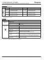
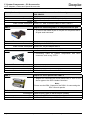
Interconnection of two Dupline nets
Coupling two Dupline nets is applicable in cases where data need to be exchanged between two systems.
These two nets can also “share“ inputs and outputs whereby the allocated addresses of such components
may be assigned only once. The channel generators use the Modbus I-RTU protocol for the data
exchange and are connected as follows via their serial interface:
9-pole plug
to DKG
9-pole plug
to DKG
1
1
2
2
3
3
4
4
5
5
6
6
7
7
8
9
Dupline Planning Aid and Product Information
9
DKK_2ED/01/03
8
February 2006 - v1.60
Page 29
5 System Components - 5.2 Central Units
5.2.1 DKG 1/DKG 2: Channel Generators 24 VDC and 115/230 VAC resp.
Doepke
Here also, the length should not exceed more than 10 m. The cable DKK 2 which is preconfigured with
these connections, can be ordered separately.
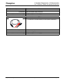
Visualisation
The serial connector of the DKG may also be used as an interface for visualisation components. For this
purpose the DKK 1 standard cable may be used.
Parallel operation of configuration with ProLine and visualisation is not possible. You will find further
details about visualisation in Chapter 4.2 "Visualisation" on Page 24.
Changing the configuration during operation
The channel generators permit configuration changes to be carried out while the system is in operation;
any changes of processes which are relevant to safety should nevertheless only be undertaken while the
process is in a “non-dangerous“ state, because the change is not without jolts.
Documentation
ProLine offers various functions for providing documentation. It is thus possible to print out following information:
• channel addresses
• time switch channels
• logic connectives
• central/master channels.
Installation in distribution cabinets
When installing the channel generators in distribution cabinets, it should be noted that the serial connection has to be arranged from the right hand side. This means that a free space of approximately 3 module
widths needs to be provided here in order to allow the programming plug to be inserted.
The space required for the connector can be reduced by using the optionally available DKA 1 front
adapter. It allows the serial cable to be connected from the front and has a width of only one module (see
also Chapter 5.9.3 "Adapters, Cables and Special Accessories" on Page 166).
Wiring Layout and Dimensions DKG 1
Page 30
February 2006 - v1.60
Dupline Planning Aid and Product Information
Doepke
5 System Components - 5.2 Central Units
5.2.1 DKG 1/DKG 2: Channel Generators 24 VDC and 115/230 VAC resp.
Wiring Layout and Dimensions DKG 2
Connections
Terminal
Description
Terminal
Description
1
Dupline signal conductor + (Dupline+)
2
Dupline signal conductor - (Dupline-)
3
Compensating connector for highly
inductive lines
7
Watchdog (-)
6
Watchdog (+)
35
Back-up battery 9 VDC
37
Back-up battery 0 VDC
Operating voltage 24 VDC
22
Operating voltage 0 VDC
Operating voltage 115/230 VAC
24
Operating voltage N
DKG 1 only:
21
DKG 2 only:
21
Indicators
Indicator
Description
Green LED
Power supply: Off – no power / On – OK
Yellow LED „ON LINE“
Dupline bus signal: Off – bus fault / On – bus OK
Yellow LED „BUSY“
Processing a job via serial connection:
Off – no processing / On – processing in progress
Red LED „FAULT“
Fault: Off – no fault / On – fault has occurred
Min.
Typ.
Max.
Dupline
Output voltage
Output current
Frequency approx. 1 kHz
Dupline Planning Aid and Product Information
February 2006 - v1.60
8.2 V, pulsed
100 mA
Page 31
5 System Components - 5.2 Central Units
5.2.1 DKG 1/DKG 2: Channel Generators 24 VDC and 115/230 VAC resp.
Min.
Doepke
Typ.
Max.
Watchdog
Type NPN-transistor (closed, when Dupline bus is OK)
Voltage
35 VDC
Rated current / load rating
100 mA
Interfaces
Type RS 232, 9-pole SUB-D socket
Length of line
Operating Voltage DKG 1
Rated operating voltage
Power consumption
Operating Voltage DKG 2
Rated operating voltage (50/60 Hz)
Power consumption
Security of data in the event of power
failure
Configuration
Clock and calendar
Switching status
Real-time clock
Accuracy
Buffer time
Terminals
Type
Contact area
Housing
Type
10 VDC
24 VDC
approx. 7 W
10 m
30 VDC
115/230 VAC
approx. 7 W
10 years
approx. 5 days(1)
not secure (priority selectable on modules)
Better than ± 1 minute/month
5 days
Screw terminals
0.4 mm ∅
2.5 mm²
Distribution installation housing for rail-mounting to
DIN EN 50022
Dimensions 144 x 78 x 65 (W x H x D in mm) / 8 modules
Material Polycarbonate
General technical data
Ambient temperature
-10°C
+45°C
Atm. humidity
85%
Encl. protection type / standards IEC60669, EN55022 / EN61000-6-3 and EN55024 /
EN61000-6-1
Order number, description 09 501 122, channel generator 24 VDC DKG 1
09 501 104, channel generator 115/230 VAC DKG 2
09 501 129, interface cable DKK 1, PC - DKG
09 501 137, interface cable DKK 2, DKG - DKG
09 501 142, 25-pole adapter DKK 3, DKK 1 - PC
09 501 143, angled adapter DKA 1
(1) Without backup power supply.
Page 32
February 2006 - v1.60
Dupline Planning Aid and Product Information
Doepke
5 System Components - 5.2 Central Units
5.2.2 DKG 20 / DKG 21-GSM: Channel Generators
5.2.2 DKG 20 / DKG 21-GSM: Channel Generators
• Generators for 128 channels each
• Serial ports for configuration and visualisation
• Channel properties, time functions and logic functions configurable
with ProLineNG PC software
• Four each integrated semiconductor inputs and outputs
• Simplest possible set-up of networks with up to 32 DKG 20 or
DKG 21-GSM
• DCF radio clock synchronization with optional DCF active antenna
• Remote control and remote monitoring via mobile phone (SMS) if
connected to optional GSM antenna (DKG 21-GSM only)
• Operating voltage 115/230 VAC
Produktbeschreibung
The DKG 20 and DKG 21-GSM channel generators are intelligent, configurable central units which generate the Dupline carrier signal for 128 channels and are thus indispensable components for every system.
Compared to the DKG 1 and DKG 2 channel generators (see Chapter 5.2.1 on Page 28) this new generation provides higher performance, offers more functions in respect of visualisation and network construction, and supports the use of a radio modem.
The DKG 21-GSM features the basic equipment of the DKG 20 but is additionally fitted with an integrated
GSM modem which enables the system not only to be remotely controlled but also to transmit events via
SMS.
In terms of software, too, these new DKGs are provided with most of the functions of the DKG 1 and
DKG 2; any differences are explained in detail below.
Configuration
These channel generators are to be configured with ProLineNG (see Chapter 5.10.1 on Page 174). The
remote configuration is possible by means of the DCI 2 (see Chapter 5.7.2 on Page 151).
DKG networks
You can link up to 32 DKG 20 or DKG 21-GSM - or a mixture of both - into one network, thus having the
use of 4096 channels. The RS485 Modbus I communication is via a shielded standard cable (e.g. ISDY 2
x 0.8mm), which may be up to 1000 m long and is connected directly to the terminals of the DKGs. It is
thus no longer necessary to provide interface converters.
The necessary termination of the RS485 bus - at the start and at the end - is accomplished by the simple
expedient of inserting jumper wires. A failsafe circuit can also be provided in this way; it will ensure that
any breakdown of network members is quickly and reliably detected.
For details refer to the respective operating instructions and to Chapter 4.1 "Networks" on Page 22.
The transfer rate is selectable between 2400 and 115,200 baud and can thus be adapted to any possibly
adverse environmental conditions. The communication parameters are set once - with the aid of the new
ProLineNG software - directly via the modbus master; repeated unplugging/replugging is therefore unnecessary.
When all channel generators (one master and up to 31 slaves) have been configured with ProLineNG, the
master will automatically initiate the data exchange whereby every individual DKG receives a transcript of
the data of all other DKGs.
Access to the data of other DKGs is always "source addressed", i.e. it is restricted to read-only. There are
two options of including external data, the so-called "references":
Dupline Planning Aid and Product Information
February 2006 - v1.60
Page 33
5 System Components - 5.2 Central Units
5.2.2 DKG 20 / DKG 21-GSM: Channel Generators
Doepke
1. Direct access within the channel objects
Every configured channel contains a list which can be filled with external references to
channels of other DKGs. Every channel listed here is "or-linked" to the configured channel.
2. Indirect access via status channels
With the new "Status Channel" object you can "import" external channels so that the status
channel always adopts the value of the imported channel. This enables easy processing in
logic connectives.
To summarize: it could be said that on the one hand the new implementation of the network capabilities is
easy, and yet on the other that it also opens up many new possibilities.
Note:
It is not possible to couple channel generator types DKG 1 or DKG 2 to a network based on
DKG 20/ DKG 21-GSM.
Visualisation
Visualisation is closely linked to the network's structure. Every DKG has an additional COM2 port, which
may be utilized either for connecting a visualising component or for operating a radio modem.
This port, too, offers the Modbus I protocol on the basis of a RS232 connection so that standard touch
screens (e.g. the Doepke DSC 3) or visualising programmes on PCs can be employed, there being the
option of setting a transfer rate between 2400 and 115,200 baud.
The extent of data access depends upon which channel generator is used for the connection:
• Without network:
Here you can read and write the data of the DKG.
• In a network at the master
Here you can read and write the data of the master and all the slaves.
• In a network at a slave
Here you can read and write the data of the connected slave, but only read the data of all
other network members.
The possibilities of visualisation have also been extended by some configuration data. It is thus now in
addition possible to change the following data:
• Time entries of the "Real-time Switch" object;
• Limit data of AnaLink objects (light sensor, temperature sensor, wind sensor and general
sensor);
• Reading and writing of the channel generator clock.
Please refer to Chapter 4.2 "Visualisation" on Page 24.
Internal real-time clock and DCF radio signal synchronisation
Like their predecessors the DKG 2x are also equipped with an internal, back-up battery supported realtime clock. You can improve its accuracy in two stages:
1. By configuring in ProLineNG a calibration with the mains frequency;
2. By connecting the optimal DDA 1 active antenna so that the clock is synchronised with the
time signal from an atomic clock. The pulse is sent via the transmitter in Rugby (UK) and has
a reception radius of approx. 1000 km.
For details on the DCF antenna please refer to Chapter 5.9.3.1 "DDA 1: DCF-Antenna for
DKG 20 / DKG 21-GSM" on Page 166.
Note:
If a network is used, the master will always update the clocks of the connected slaves. It is
therefore advisable to connect the active antenna to the master.
Integrated semiconductor inputs and outputs
Both the DKG 20 and the DKG 21-GSM are equipped with 4 each semiconductor inputs and outputs
which have to be separately supplied with a voltage of between 10 and 30 VDC. The processing of the
Page 34
February 2006 - v1.60
Dupline Planning Aid and Product Information
Doepke
5 System Components - 5.2 Central Units
5.2.2 DKG 20 / DKG 21-GSM: Channel Generators
signals takes place in the logic connectives, where 8 markers are reserved for input and output.
Terminals
Description
Markers
7..10
semiconductor inputs In1..In4
Q1..Q4
13..16
semiconductor outputs Out1..Out4
Q5..Q8
Saving the status upon power failure
The built-in EEPROM memory now makes it possible permanently to save the status of all channels in the
event of a new start or a power failure. This means that the switching status of e.g. toggle-switch functions
and real-time switches are restored when restarting, provided this option is activated in the configuration.
Radio modem
In addition to the modbus protocol for visualisation, the COM2 port offers the option of operating the radio
modem by the Finnish manufacturer Satel. With the aid of this modem it is possible to set up a locally dispersed Dupline system whereby the distance between the radio modem master and the associated
slaves can be up to 3 km.
Even if such a system consists of several channel generators - one master ("Radio Modem Central") and
up to 31 slaves ("Radio Modem Substation") - a total of 128 addresses will be available. The master
undertakes all automatic tasks within the system and polls cyclically the data of the connected slaves. The
latter do not get their own configuration.
The following diagram illustrates the structure of such a system:
Note:
It is not possible to transmit AnaLink data (e.g. temperature or light level data) via the radio
modem - in this case it is necessary to make use of multiplex analog data.
GSM modem for SMS data transfer (DKG 21-GSM only)
The DKG 21-GSM is equipped with a GSM modem which enables remote control of the system via SMS,
enquiry of current data, or transmission of events in the form of SMS messages.
To operate this modem you require the following accessories:
Dupline Planning Aid and Product Information
February 2006 - v1.60
Page 35
Doepke
5 System Components - 5.2 Central Units
5.2.2 DKG 20 / DKG 21-GSM: Channel Generators
1. A mobile phone antenna with FME connector, e.g. the Doepke DGA 1;
2. A standard 3V SIM card from a mobile phone service whose transmitter network covers the
location of the DKG 21-GSM. This card requires the preset PIN code "9090" and must have
been enabled for SMS data transfer.
The range of functions of the GSM modem is the same as that of the - now no longer available - GSM 8:
• Specification of up to 4 mobile phone numbers, which can poll data or have events
transmitted to them;
• Event messages are sent either to all 4 phone numbers, or sequentially to one after the other
until an acknowledgement is received;
• Specification of up to 4 mobile phone numbers to which changes in switching status can be
restricted (generally all mobile phones can send commands);
• Password protection
• Specification of a facility identification text which is always contained in the SMS message.
Depending upon the mobile network, event messages may also be transferred to landline numbers and
will there be output as a spoken report. Alternatively, it is often possible to forward the SMS to landline
numbers of fax machines; in which case the result will be in the form of a protocol printout.
A list of the supported objects can be found in the ProLineNG manual.
Wiring Layout and Dimensions
Note:
Page 36
The wiring layout of the DKG 20 corresponds to that of the DKG 21-GSM with the
exception of there being no GSM antenna socket.
February 2006 - v1.60
Dupline Planning Aid and Product Information
Doepke
5 System Components - 5.2 Central Units
5.2.2 DKG 20 / DKG 21-GSM: Channel Generators
75
70
DKG 20/DKG 21-GSM
9-pole DSUB plug
1
1
2
2
6
6
TxD
3 RxD
3
4
4
5
5
77
45
7
8
9
9
GND
D3931246_6A
7
8
25
PC
9-pole DSUB jack
3931246_2a
Wiring in an RS485 Network
Connections
Terminal
1
7..10
Description
Terminal
Description
Dupline signal conductor + (D+)
2
Dupline signal conductor - (D-)
Semiconductor inputs In1..In4
11
0 VDC
operating
inputs/outputs
12
+10..30 VDC operating voltage for
inputs/outputs
21
27
voltage
for
13..16
Semiconductor outputs Out1..Out4
Operating voltage: 115/230 VAC (L)
24
Operating voltage: 115/230 VAC (N)
RS485 bus termination
28
RS485 failsafe termination B
Dupline Planning Aid and Product Information
February 2006 - v1.60
Page 37
Doepke
5 System Components - 5.2 Central Units
5.2.2 DKG 20 / DKG 21-GSM: Channel Generators
Connections (Continued)
Terminal
Description
Terminal
Description
29
RS485 failsafe termination A
30
RS485 signal B (+)
31
RS485 signal A (-)
32
0 VDC operating voltage output for
inputs/outputs(1)
33
+10..30 VDC operating voltage output for inputs/outputs(1)
34
DCF signal V+
35
DCF signal S- in
36
DCF signal V-
(1) This voltage output may only be used for the power supply of the semiconductor inputs/outputs when the RS485 connector is
not used.
Pauses
Pulsing
Flashing
Off
Indicator
On
Indicators
Green LED
Description
Power supply
Power OK
No power
Yellow LED
Dupline bus
Bus OK
No signal
Short-circuit - manual restart required
4
4
Red LEDs „D1“ and
„D2“
Short-circuit - automatic restart
RS232 (D1: COM 1 / D2: COM2)
Data transfer
No communication
Transfer of application in progress
4
4
Data transfer error
5
3
Transfer of application failed
Red LED „D3“
RS485 (network connection)
No communication
Data transfer
Red LED
(DKG 21-GSM only)
Page 38
GSM modem (DKG 21-GSM only)
OK or no modem present
1
3
Connecting to net
2
2
SIM card missing
3
5
No mobile phone network present
5
3
No answer from modem
1
Sending SMS
2
Receiving SMS
February 2006 - v1.60
Dupline Planning Aid and Product Information
Doepke
5 System Components - 5.2 Central Units
5.2.2 DKG 20 / DKG 21-GSM: Channel Generators
Min.
Typ.
Max.
Dupline
Output voltage
Output current
Cycle time (16/128 channels)
Short-circuit protection
Operating Voltage
Rated operating voltage
Power consumption
Power-on delay
Output voltage Terminals 32/33
Digital Outputs
Type
Short-circuit protection
Rated operating voltage
Rated current / load rating
Digital Inputs
Type
Threshold limit
Rated operating voltage
Rated current
Serial interface COM1
Type
Transmission speed
Transmission parameters
Line length
Serial interface COM2
Type
Transmission speed
8.2 V, pulsed, frequency approx. 1 kHz
24 ms
130 mA
136 ms
Yes
115/230 VAC ±15% (45..65 Hz)
Typ. 7 VA / 3 W
2.5 s
10 VDC ±1 V
4 PNP-transistors, programmable
No
35 VDC
100 mA
Semiconductor
On: > 5.5 V, Off: <1.5 V
6 V AC/DC
30 V AC/DC
6 mA
RS 232, 9-pole SUB-D socket, Modbus-I-RTU
115 kBaud
8 bit, no parity, 1 stop bit
3m
RS 232, 9 pole SUB-D socket, Modbus-I-RTU
adjustable: 2400, 4800, 9600, 19200, 38400, 57600,
115200 Baud,
8 bit, no parity, 1 stop bit
3m
Transmission parameters
Line length
Serial interface RS 485
Type RS 485, terminals, Modbus-I-RTU
Transmission speed adjustable: 2400, 4800, 9600, 19200, 38400, 57600,
115200 Baud,
Line length
1000 m
Real-time clock
Accuracy better than ± 1 minute/month
Buffer time
48 h
GSM modem (DKG 21-GSM only)
Type Siemens TC35 Dual band (EGSM900 and GSM1800)
Antenna connector FME socket
Output power Typ. 2 W (EGSM900) / 1 W (GSM1800)
Dupline Planning Aid and Product Information
February 2006 - v1.60
Page 39
Doepke
5 System Components - 5.2 Central Units
5.2.2 DKG 20 / DKG 21-GSM: Channel Generators
Min.
Typ.
Max.
Terminals
Type Screw terminals
Contact area
0.4 mm ∅
2.5 mm²
Housing
Type Distribution installation housing acc. to DIN43880 for rail-mounting to DIN EN 50022
Dimensions 144 x 78 x 65 (W x H x D in mm) / 8 modules
Material Polycarbonate
General technical data
Ambient temperature
Atm. humidity
Weight
Encl. prot. type / standards
Order numbers, description
Page 40
0°C
Max. 80% (exposure to dew not permissible)
640 g
IEC60664, IP 20
09 501 191, Active DCF antenna DDA 1
09 501 190, GSM antenna DGA 1
09 501 188, channel generator DKG 20
09 501 189, channel generator DKG 21-GSM
February 2006 - v1.60
+50°C
Dupline Planning Aid and Product Information
Doepke
5 System Components - 5.3 Inputs
5.3.1 DBM 1: Surface-Mounted Proximity Detector
5.3 Inputs
5.3.1 DBM 1: Surface-Mounted Proximity Detector
• Passive infrared sensor, which reacts to human movement
• For indoor use
• Range up to 12 m with a 90° angular coverage, reaction time
selectable
• Power supplied by the Dupline bus
Product Description
The DBM 1 infrared proximity detector detects the movement of people inside rooms and transmits the
data via the Dupline bus. It is therefore suitable e.g. for burglar alarm and lighting control purposes.
The DBM 1 has a range of 12 m and an angular coverage of 90°. Its various switches permit selection of
the transmission time on the Dupline bus and the configuration of the switching characteristic (“normally
open“ or “normally closed“ - sabotage control setting), and the activation of the LED operation check indicator.
Any slow movements, which correspond to a scanning frequency of less than 0.5 pulses/second, are not
detected. Neither are fast movements corresponding to a scanning frequency above 5 pulses/second are
registered.
Several DBM 1 units installed in one room do not affect each other.
It does not require an external power supply as it is supplied by the Dupline signal line.
Notes on Applications
Installation
The DBM 1 should not be mounted in the following locations:
• in outdoor areas;
• in locations which are exposed to either sunlight or car headlights (direct exposure);
• in locations subject to direct air flow from heating or air conditioning equipment;
• in locations subject to rapid temperature changes;
• in locations subject to strong vibrations;
• in the vicinity of glass or other objects which reflect the emitted infrared rays.
Maximum capacity
Up to 32 proximity detectors may be connected to one Dupline bus. With 32 connected DBM 1 no further
inputs or outputs can be operated.
Scanning angle / distance
Dupline Planning Aid and Product Information
February 2006 - v1.60
Page 41
Doepke
5 System Components - 5.3 Inputs
5.3.1 DBM 1: Surface-Mounted Proximity Detector
Wiring Layout and Dimensions
Dupline +
Dupline -
Q
ON
GND DUP
1 2 3 4
WALK
TEST
TRANSM.
TIMER
3931184_1B/01/12
Q
1: Western socket for address encoding.
2: Terminals for connecting the Dupline bus
3: LED for movement test
4: DIP switches (see below)
5: Potentiometer for fine tuning the transmission time
Connections
Terminal
Description
Terminal
DUP
Dupline signal conductor + (Dupline+)
COM
Description
Dupline signal conductor - (Dupline-)
Dupline Channel Allocation
Channel
1
Description
Channel
Switching signal (NCC or NOC)
2..8
Description
Not assigned
Indicators
Indicator
Red LED
Description
Indicator for movement test (disconnectable)
DIP Switches
Switch
Description
1
Indicator for movement test
2
Transmission time
3
Switching characteristic on Dupline bus
4
Time prolongation of the alarm signal
Min.
OFF
ON
LED off
LED on
12 s to 2 min
1 min to 10 min
NOC
NCC
Off
On
Typ.
Max.
Dupline
Current input
2 mA
Input channels none
Output channels 1 alarm-/switching signal (NCC or NOC)
Page 42
February 2006 - v1.60
Dupline Planning Aid and Product Information
Doepke
5 System Components - 5.3 Inputs
5.3.1 DBM 1: Surface-Mounted Proximity Detector
Min.
Switch-on delay
Typ.
1 min
Max.
Sensor
Type Infrared, wavelength 7 to 14 µm
Scanning method 24 zones in 3 areas
Scanning angle 90°
Scanning range
Response rate
0.5 pulses/s
12 m
5 pulses/s
Terminals
Type Screw terminal
Contact area
0.4 mm ∅
1.5 mm²
Housing
Type White surface-mounted housing
Dimensions 104 x 55 x 57 (W x H x D in mm)
Material Lens: polyethylene
General technical data
Ambient temperature
-10°C
Atm. humidity
Encl. protection type / standards IP 40 (for indoor use)
Weight approx. 150 g
Order number, description 09 501 134, Proximity detector DBM 1
Dupline Planning Aid and Product Information
February 2006 - v1.60
+50°C
85%
Page 43
Doepke
5 System Components - 5.3 Inputs
5.3.2 DIR 2: Infrared Remote Control
5.3.2 DIR 2: Infrared Remote Control
•
•
•
•
8 x 8 different transmission channels (64 switching options)
Power supply of receiver provided by the Dupline bus
Range of 15 m
Transmitter powered by standard batteries
Product Description
The Dupline infrared remote control consists of two components: a receiver (DIR 2) and a hand transmitter (DIR 2T).
Each DIR 2 receiver is capable of receiving 8 switching commands and of transmitting these to the coded
channels of the Dupline system. Up to 8 switching commands each pertaining to one of the 8 switching
groups A...H can be selected via the DIP switch of the DIR 2 and via the rotary switch of the DIR 2T transmitter. However, the switching groups (A...H) have no connection with the channel groups of the Dupline
system.
By grouping it is thus possible to configure up to 64 switching commands with 8 receivers and one or
more hand transmitters and to remotely operate within one room. Provision for labelling on the back of the
transmitter facilitates the operation.
Notes on Applications
3931222_1A
1. Receiver
The receiver must be sited so that “visual contact“ between hand transmitter and receiver is ensured and
reflection reception is possible. In so doing, the maximum range of 15 m may not be exceeded. Walls and
glass panes prevent reception and are therefore to be avoided. In addition, light and exposure to sun can
impair reception characteristics.
The following diagram shows the recommended mounting of the receivers on the wall:
2. Transmitter
The transmitter is powered by two standard “AA mignon cell“ batteries
Page 44
February 2006 - v1.60
Dupline Planning Aid and Product Information
Doepke
5 System Components - 5.3 Inputs
5.3.2 DIR 2: Infrared Remote Control
Wiring Layout and Dimensions / DIP-Switches
Dupline +
Dupline -
B
A
ON
ON
DIP
UP
1 2 3 4
Switching group:
1 2 3 4
E
ON
C
DIP
ON
1 2 3 4
F
ON
DIP
D
ON
DIP
1 2 3 4
G
DIP
ON
DIP
H
ON
DIP
DIP
ON OFF
3931222_2A
ON
DIP
1 2 3 4
1 2 3 4
1 2 3 4
1 2 3 4
3931222_3A
Switching group:
1 2 3 4
Connections
Terminal
Description
Terminal
Description
1
Dupline signal conductor + (Dupline+)
2
Dupline signal conductor - (Dupline-)
Dupline Channel Allocation
The assignment between Dupline addresses and the switching commands is independent from the
channel groups of the transmitter/receiver unit and is as follows:
Channel
1..4
Description
Channel
Transmitter switching commands 1..4
5..8
Description
Transmitter switching commands 5..8
Indicators
Indicator
Red LED
Description
Reception of valid telegrams:
Off: No, or invalid, telegram received
On: Valid telegram received(1)
(1) After switching on the bus the LED remains activated until the first valid command has been received.
Technical Data
Min.
Typ.
Max.
1.8 mA
3.2 mA
Dupline
Current input
Input channels none
Output channels 8 switching commands
Terminals
Type Plug terminals, screw terminals included in package
Contact area
0.4 mm ∅
2.5 mm²
Housing
Type Neutral, polar-white housing
Dupline Planning Aid and Product Information
February 2006 - v1.60
Page 45
Doepke
5 System Components - 5.3 Inputs
5.3.2 DIR 2: Infrared Remote Control
Technical Data (Continued)
Min.
Typ.
Max.
Dimensions 80 x 80 x 15 (W x H x D in mm), surface- or flush-mounted
Material Polycarbonate
General technical data
Ambient temperature
-10°C
+45°C
Atm. humidity
85%
Encl. protection type / standards EN55022 / EN61000-6-3 and EN55024 / EN61000-6-1
Order number, description 09 501 169, IR-receiver DIR 2
Min.
Typ.
Max.
Operating Voltage
Type 2 “AA mignon cell“ batteries, 1.5 V
Transmission
Type
Carrier frequency
Range(1)
Number of switching channels
Number of channel groups
Housing
Type
Dimensions
General technical data
Ambient temperature
Atm. humidity
Encl. protection type / standards
Order number, description
Infrared light, 950 nm
38 kHz
approx. 15 m
8
8, “A” to “H”
Gray / Side parts black (rubberized)
63 x 95 x 28 (W x H x D in mm)
-10°C
+45°C
85%
09 501 219, IR-transmitter DIR 2T
(1) The maximum range is dependant upon the ambient temperature and light intensity and may therefore vary.
Page 46
February 2006 - v1.60
Dupline Planning Aid and Product Information
Doepke
5 System Components - 5.3 Inputs
5.3.3 DLUX: Surface-Mounted Light Level Sensor
5.3.3 DLUX: Surface-Mounted Light Level Sensor
•
•
•
•
•
Permits the transmission of light levels via the Dupline bus
Light range from 0.1 Lux to 100 kLux
Compact size
Power supplied by the Dupline bus
Suited for outside use
Product Description
The DLUX analog light level transmitter is designed to convert analog light intensity data for transmission
via the Dupline bus. The light intensity data can be transmitted on 8 independently encodable channels
and can thus be compared in the channel generator with 8 different threshold values in order to control
loads. Because of its compact design, the DLUX can be mounted unobtrusively on e.g. walls of houses. It
does not require an external power source as it is supplied by the Dupline signal line.
Notes on Applications
Installation
The DLUX should normally be fitted in a position where light from outside illuminates the room to be controlled, e.g. on a wall with windows which are to be blacked-out by shutters. Any shadow thrown on the
sensor by e.g. eaves or similar protrusions results in the sensor‘s registering higher levels of darkness
and, if it is functioning as a twilight switch, leads to its loads being switched on too early and switched off
too late, which has to be considered when defining the threshold values.
Optic feedback from light shining on the DLUX must be avoided as far as possible, as the effect of such
light on the sensor when the lighting is switched on may result in a cyclic make and break operation.
When selecting the installation site, consideration should also be given to environmental factors (dust,
dirt, and snow) which over the longer term will reduce the light transmission of the DLUX.
Wiring Layout and Dimensions
40 mm
30 mm
20 mm
83 mm
Encoding
Flat Pack
Connector
1
2
3931186BE
UP
Dupline +
Dupline -
Dupline Planning Aid and Product Information
February 2006 - v1.60
Page 47
Doepke
5 System Components - 5.3 Inputs
5.3.3 DLUX: Surface-Mounted Light Level Sensor
Connections
Terminal
Red
Description
Dupline signal conductor + (Dupline+)
Terminal
Description
Grey
Dupline signal conductor - (Dupline-)
Dupline Channel Allocation
Channel
1..4
Description
Channel
Light intensity value
5..8
Description
Light intensity value
Indicators
none
Min.
Typ.
Max.
Dupline
Current input
350 µA
400 µA
Input channels none
Output channels 8 light intensity outputs, AnaLink method
Reaction time
6 s(1)
450 µA
34 s(2)
Light Sensor
Type
Measuring range
Deviation from characteristic(4)
Measuring error over temperature range(4)
Terminals
Type
Contact area
Housing
Type
Dimensions
Material
General technical data
Ambient temperature
Atm. humidity
Encl. protection type / standards
Order number, description
(1)
(2)
(3)
(4)
Photodiode with linearized characteristic(3)
0.1 Lux
100 kLux
-10%
+10%
-30%
+30%
Screw terminal
0.4 mm ∅
2.5 mm²
Transparent surface-mounted housing
40 x 83 x 43 (W x H x D in mm)
Lexane
-10°C
+60°C
90%
IP44
09 501 110, Light level sensor DLUX
When put into service, channel generator with 16 channels.
When put into service, channel generator with 128 channels.
Characteristic adapted to human perception of brightness.
In relation to linearized value.
Page 48
February 2006 - v1.60
Dupline Planning Aid and Product Information
Doepke
5 System Components - 5.3 Inputs
5.3.4 DNP 8E: 8-Way Binary Input Board (24 VDC)
5.3.4 DNP 8E: 8-Way Binary Input Board (24 VDC)
•
•
•
•
Predestined for use in control boards
8 binary inputs
LED indicator for operating voltage and bus signal
Support for mounting on DIN-rail available
Product Description
The DNP 8E input board offers 8 binary inputs. Because of its size and connection data it is particularly
suitable for fitting in control and indicator boards where open circuit boards can be installed.
The DNP 8E permits contacts and switches to be connected towards the 0 V-signal of the power supply.
The board is equipped with a LED to indicate that the bus signal is correct and a LED to show that operating voltage is applied. Each input operates with pulse stretching respectively delay, so that even
extremely short changes in the input signal are registered and transmitted by the system.
Notes on Applications
When connecting the board it should be noted that - contrary to other inputs and outputs - the 0 V lead as
well as the Dupline signal conductor (-) must be connected to the “GND“ terminal.
Moreover, any push-buttons or switches which when operated connect with 0 V may not be directly connected to the Dupline signal conductor (-). For further details please refer to Chapter 2.3.4.4 "Components with external DC power supply" on Page 15.
Note:
This input board is not suited for dimming of lamps with the dimmers DDM 1Rplus,
DDMU 1Rplus, DDM 2 und DDMU 2. Please use the operating signal sensors of DSS series
or the signal converters of DSU series instead.
Wiring Layout and Dimensions
Dupline Planning Aid and Product Information
February 2006 - v1.60
Page 49
Doepke
5 System Components - 5.3 Inputs
5.3.4 DNP 8E: 8-Way Binary Input Board (24 VDC)
Connections
Terminal
Description
Terminal
Description
I1..I4
Inputs 1..4
I5..I8
Inputs 5..8
DUP
Dupline signal conductor+ (Dupline+)
GND
Dupline signal conductor - (Dupline -)
and 0 V operating voltage
POW
24 VDC operating voltage
DC+
not connected
Dupline Channel Allocation
Channel
1..4
Description
Channel
Inputs 1..4
5..8
Description
Inputs 5..8
Indicators
Indicator
Description
Green LED
Operating voltage:
Off – no supply / On – operating voltage OK
Yellow LED
Dupline bus:
Off – bus fault / On – bus OK
Min.
Typ.
Max.
Dupline
Current input
100 µA
Input channels 8 semiconductor inputs (channels 1..8)
Output channels none
Inputs
Type
No-load voltage
Contact load
Peak current at make
Transition resistance
Length of line
Operating Voltage
Rated operating voltage
Current input
Current at make
Terminals
Type
Contact area
Housing
Type
Dimensions
General technical data
Ambient temperature
Atm. humidity
Page 50
8 contacts (via NPN transistors)
8.0 VDC
17 mA
20 mA
100 Ohm
3m
10 VDC
24 VDC
20 mA
30 VDC
1A
Screw terminal
0.4 mm ∅
2.5 mm²
Open circuit board
approx. 73 x 59 (W x H in mm)
-20°C
20%
February 2006 - v1.60
+50°C
80%
Dupline Planning Aid and Product Information
Doepke
5 System Components - 5.3 Inputs
5.3.4 DNP 8E: 8-Way Binary Input Board (24 VDC)
Min.
Typ.
Max.
Encl. protection type / standards Accessories 4 retaining clips for mounting the assembly. Optional: Support
bracket for mounting on DIN-rail
Order number, description 09 501 139, 8-way input DNP 8E
09 501 130, DIN-rail support bracket DPH 1
09 501 152, DIN-rail support bracket DPH 2
Dupline Planning Aid and Product Information
February 2006 - v1.60
Page 51
5 System Components - 5.3 Inputs
5.3.5 DPM 1: Presence Detector
Doepke
5.3.5 DPM 1: Presence Detector
• Extra sensitive, passive infrared sensor, which reacts to thermal
movement
• Radius of detection max. 5 m, 360º
• Integrated twilight switch and power input
• Selection of operating modes
• For use indoors
Product Description
The DPM 1 presence detector is a locally installed component of the Dupline installation system and enables the presence of people to be monitored and any movements within rooms to be detected. Its typical
power consumption is only 560 µA. Its highly sensitive infrared optical unit, with a 360º scanning angle
and a mounting height of approx. 2 m above the persons to be detected, can register the slightest temperature movements of people, animals or objects within a 5 m radius.
Being equipped with an integrated twilight sensor enables the DPM 1 to be operated dependent upon the
light conditions in the room. The light level below which the detector is to be triggered is adjustable
between 0.2 and 200 Lux via the potentiometer on top of the housing.
The signal function of the DPM 1 can be influenced via the Dupline bus; thus the Dupline channels can
permanently enable, or disable, the infrared sensor. By means of feeding back the switching channel for
the light to the detector you therefore have the possibility of preventing a continuous switching on/off.
With the rotary switch, accessible when the housing is opened, the desired operating mode can be set:
AUTO (internal twilight switch utilized), ON (without twilight switch) and OFF (external twilight switch useable).
In addition, the DPM 1 offers an electrically isolated 0..30 V AC/DC input, via which an external signal
may be input in the Dupline bus and processed further.
Notes on Applications
Mounting
The location of the DPM 1 substantially affects its functionality. For this reason please observe the following points:
• The DPM 1 is designed exclusively for ceiling mounting.
• Do not install the DPM 1 in the immediate vicinity of heat sources such as e.g. lamps or
radiators.
• Do not install the DPM 1 near moving objects such as ventilators.
• Please ensure that the DPM 1 is not exposed to strong air flows as these might be registered
as movements.
• Attach the DPM 1 only to surfaces free from vibration.
• Please ensure that the twilight sensor is not exposed to a direct light source as this might
result in undesired switching.
• The scanned area should not be restricted by large objects such as e.g. furniture.
• If only small or few movements are to be detected, then a time delay, configured at the
channel generator, can prevent the premature switching off of the lighting.
The DPM 1 can be either surface-mounted, using the mounting plate supplied, or flush-mounted in an
installation box (dia. 68 mm). In both cases the fixing screws supplied can be used.
Operating Modes
The DPM 1 is equipped with two controls:
• a rotary potentiometer for setting the switching threshold, this is located next to the infrared
Page 52
February 2006 - v1.60
Dupline Planning Aid and Product Information
Doepke
5 System Components - 5.3 Inputs
5.3.5 DPM 1: Presence Detector
lens and
• the operating mode rotary switch on the circuit board.
These controls enable you to influence the function of the twilight sensor in relation to the presence detector. Thus different applications are possible:
• Twilight-dependent operation of the presence detector:
The DPM 1 operates automatically in accordance with the selected twilight setting. Only
when the lighting is below the set level will the DPM 1 respond upon detecting a person and
can thus be used to switch the lighting in a room on/off.
• Twilight-independent operation of the presence detector:
The DPM 1 ignores the light conditions in the room and responds every time a person is
detected. It can thus be used purely as a proximity detector.
• Operating the presence detector as a slave in a group of DPM 1s:
Any number of DPM 1s can signal the presence of a person in dependence upon a twilight
sensor. With this group option you can ensure that all presence detectors in a room with
different lighting zones are working in unison.
Sabotage Protection
Channel 7 of the DPM 1 generates a static "1" signal. If it is disconnected from the Dupline bus, this can
be detected by means of an appropriate configuration in the channel generator, and an alarm signal triggered. For this purpose it is advisable to use an alarm system in the DKG.
Wiring Layout and Dimensions
+24 V
0V
1
OFF
ON
AUTO
E2
E2
2
D+
D-
3931254_2A
3931254_1A
3
D+
D-
1: Operating mode rotary switch
2: RJ12 jack for address encoding.
3: Potentiometer for adjustment of twilight sensor’s switching threshold.
Connections
Terminal
Description
Terminal
D+
Dupline signal conductor + (D+)
E2
Opto-decoupled
(0..30V AC/DC)
input,
potential
Dupline Planning Aid and Product Information
1
Description
D-
Dupline signal conductor - (D-)
E2
Opto-decoupled
(0..30V AC/DC)
February 2006 - v1.60
input,
potential
2
Page 53
Doepke
5 System Components - 5.3 Inputs
5.3.5 DPM 1: Presence Detector
Scanning Angle / Distance
Draufsicht
Top View
5m
Seitenansicht
Side View
X
5m
Y
50°
41°
2.5m
2.5m
0°
0°
2.5m
2.5m
41°
50°
5m
X-Y Querschnitt
X-Y Cross section
Detektierungszone
Detection zone
3m Y
2
1
4m
3
2
max. 5.66 m
1
1
2
3
4m
x
1
2
3m
max. 7.42 m
3931254_3A
5m
Hinweise:
1. Das x-y-Diagramm zeigt die Messbereiche
(projeziert auf die x-y-Ebene).
2. Die unterschiedlichen Muster zeigen die Messbereiche der 5 optischen Achsen mit den 16
Linsen. Ein Objekt,dessen Eigentemperatur sich
von der Hintergrundtemperatur unterscheidet
und sich von einem Messfeld zum anderen
bewegt, wird sicher erkannt.
Remarks:
1. The x-y cross sectional diagram shows the
detection area.
2. The differences in the detection zone patterns
are indicative of the projections of the 16 lenses
with single focal point and with five optical axes.
An object whose temperature differs from the
background temperature and which crosses
within the detection zone will be detected.
Dupline Channel Allocation
Channel
Description
Channel
Description
1
Enable infrared
sensor(1)
5
Movement detection
2
Disable infrared sensor(2)
6
Twilight switch active
3
Not assigned
7
Permanent signal(3)
4
Not assigned
8
Status opto-decoupled input
(1) With Auto mode: Feedback from channel 5.
With Off mode: Activation of DPM 1 by manual enabling.
(2) Has priority over channel 1.
(3) Signal for sabotage protection.
Indicators
none
Page 54
February 2006 - v1.60
Dupline Planning Aid and Product Information
Doepke
5 System Components - 5.3 Inputs
5.3.5 DPM 1: Presence Detector
Min.
Typ.
Max.
Dupline
Current input
280 µA
560 µA
1 mA
Input channels 4 (proximity, twilight switches, sabotage protection, input)
Output channels 2 control channels (infrared sensor enable/disable)
Infrared sensor
Type Passive infrared sensor with heat detection
Scanning Radius(1)
5m
Scanning angle
360°
Response time(2)
45 s
Twilight sensor
Type Light-dependent resistor, sensitivity adjustable
Switching threshold
0.2 Lux
200 Lux
Hysteresis factor
1.5
Inputs
Type Opto-decoupled semiconductor inputs for DC and AC voltage
Input voltage
0V
30 V
Switching threshold
3V
Operating voltage
Not required (from Dupline signal conductor)
Terminals
Type
Screw terminals
Contact area
0.4 mm ∅
2.5 mm²
Housing
Type polar-white housing for surface- and flush-mounting
Dimensions surface-mounted: 80 x 80 x 35 (W x H x D in mm)
flush-mounted: surface 15 mm, depth 20 mm
Material Polycarbonate
General technical data
Ambient temperature
-10°C
+50°C
Atm. humidity max. 85% (exposure to dew not permissible)
Encl. protection type / standards IP20, EN55022 / EN61000-6-3 and EN55024 / EN61000-6-1
Order number, description 09 501 201, Presence detector DPM 1
(1) When mounted 2 m above the persons to be detected.
(2) After bus voltage is applied.
Dupline Planning Aid and Product Information
February 2006 - v1.60
Page 55
5 System Components - 5.3 Inputs
5.3.6 DRD 3: Smoke and Fire Detector
Doepke
5.3.6 DRD 3: Smoke and Fire Detector
•
•
•
•
•
•
Smoke detector according to Tyndall effect
Detection of smouldering fires and flaming fires with smoke development
Without radioactive sources
Detection of up to 60 m²
Transmission of alarms and life signal via Dupline
Operating voltage supplied by Dupline bus
Product Description
The smoke detector DRD 3 allows an early detection of smouldering fires as well as flaming fires that
develop smoke. It operates on the proven light scatter principle. Inside the sensing chamber a light source
and a light sensor are arranged so that light normally does not fall on the sensor. It is only when airborne
particles enter the chamber that light is scattered onto the sensor (Tyndall effect) to produce the electrical
signal. This design means that no radioactive source is required.
The DRD 3 only needs the connection to the Dupline conductors. The smoke alarm as well as the status
signal, which indicates the correct connection between the smoke detector and the in-built Dupline circuit
board as well as a successful self-test, are transmitted via the Dupline bus.
Besides the alarm, the LED in the housing of the DRD 3 shows also the state of function of the device. At
the same time, the LED is the test button which allows a visual check of the alarm function, whereas also
an alarm is given via Dupline bus.
The power supply solely is done by means of the bus signal - a battery is not required.
Notes on Applications
To achieve a minimum protection, one DRD 3 should be installed in front of the of each sleeping area
respectively in each floor. A better protection will be reached if one smoke detector is present in every
room (except for the kitchen and the bath - here, false alarms are possible due to steam development).
When using the DRD 3, following issues have to be observed:
• Rooms may have a floor area of up to 60 m² and a height of up to 6 m;
• Hallways and narrow corridors may have a width of 3 m and a length of 15 m;
• The mounting location shall be as near as possible in the centre of the room;
• A gap of at least 0.5 m must be maintained from walls and furniture.
The DRD 3 must not be mounted at following locations:
• near to ventilation ducts or strong draughts;
• directly in the apex of pitched roofs (a minimum distance of 30 cm from the apex must be
kept);
• in rooms where - under normal conditions - a lot of steam, dust or smoke is present (for
example in workshops, bathrooms and laundry rooms);
• in rooms where the temperature rises above +40 °C or falls below +5 °C.
The bus interface board DFMS 3, which is integrated in DRD 3, may also ordered separately. Doing this, it
is possible to connect smoke detectors equipped with a battery or siren to Dupline systems. Please ask
us!
Page 56
February 2006 - v1.60
Dupline Planning Aid and Product Information
Doepke
5 System Components - 5.3 Inputs
5.3.6 DRD 3: Smoke and Fire Detector
Wiring Layout and Dimensions
Position of the PCB (A) in DRD 3: The orientation of the Address coding of the PCB (A) with hand
PCB has to be so that the 5-pin terminal (C) runs into the encoder cable DKP 2 at the terminal (D).
wholes of the base PCB.
Connections
Terminal
Description
Terminal
Description
red (1)
Dupline signal conductor + (Dupline+)
grey (2)
Dupline signal conductor - (Dupline-)
Dupline Channel Allocation
Channel
1
2
Description
Alarm signal (active on alarm)
Status
signal(2)
D(1)
Channel
A1
3..8
Description
Not assigned
D(1)
-
-
(1) Default channel address encoding ex-factory
Dupline Planning Aid and Product Information
February 2006 - v1.60
Page 57
Doepke
5 System Components - 5.3 Inputs
5.3.6 DRD 3: Smoke and Fire Detector
(2) Active when signal conductors and smoke detector are connected: every 50 s this channel is active for two cycles.
Indicators
Indicator
Red LED
Description
Operation indicator:
Short flash one time every 50 s (life signal): Smoke detector is OK
Short flash every 0.6 s: Fire alarm
Min.
Typ.
Max.
Dupline
Current input
200 µA
Input channels 2 (alarm signal, status signal)
Output channels none
650 µA
Detector
Type optical (to Tyndall effect)
Operating Voltage
not necessary (from Dupline signal)
Terminals
Type Strain-relief clamps
Contact area
0.4 mm ∅
1.5 mm²
Housing
Type Housing for installation at ceilings
Dimensions ∅ 100 x 51 (in mm)
Material Polycarbonate
General technical data
Ambient temperature
-10°C
+60°C
Atm. humidity 20%..90% (exposure to dew not permissible)
Encl. protection type / standards CE, IP 43, EN ISO 12239; this model bases on a device
with the VdS-Certification G 202055
Order number, description 09 501 217, Smoke detector DRD 3
Page 58
February 2006 - v1.60
Dupline Planning Aid and Product Information
Doepke
5 System Components - 5.3 Inputs
5.3.7 DRT 1: Room Thermostat in Installation Housing
5.3.7 DRT 1: Room Thermostat in Installation Housing
•
•
•
•
•
Thermostat with selectable temperature range of +14°C to +28°C
For the temperature-dependent regulation of any heating units
Night-time reduction by 4°C selectable via input channel
Easiest possible address encoding via rotary switch
Neutral white coloured combined surface or flush-mounted installation
housing
• Power supplied by Dupline bus
Product Description
The DRT 1 is a manually settable room thermostat which transmits to the Dupline bus one switching
channel for regulating units such as e.g. radiator control valves.
The desired temperature can be preselected with the setting valve within a range of +14°C to +28°C and
is then compared to the room temperature; if the set temperature is below the room temperature, the
switching channel will be activated or, conversely, the channel will be deactivated. The hysteresis is
±0.25°C.
An input channel permits the night-time reduction to be pre-programmed: if this is set the DRT 1 will lower
the room temperature by 4°C in relation to the preselected temperature.
Notes on Applications
The address, to which the switching channel is to be transmitted, can be freely selected with rotary
switches within an address range between A1 to P8.
The channel for the night-time reduction can be preset via a rotary switch within an address range of B1 to
B8, but cannot be switched off. When not using the night-time reduction, it should be ensured that other
input channels do not energize the set channel.
The DRT 1 should be so mounted that the air vents are not obstructed by items such as e.g. curtains.
The installation housing, consisting of an air-permeable cover, the installation frame and a surfacemounted frame, is suitable for both surface-mounting and flush-mounting in standard socket boxes.
The DRT 1 requires no external power supply as it is supplied by the Dupline signal line.
.3
5
.4.
C
HIJK
.6.7.
5
.4.
G
8
1.2
1.2
PAB
1 2
8
.3
O
LMN
.6.7.
Wiring Layout and Dimensions
DEF
4,6
4.6
84,0
55,8
84.0 55.8
20
18
16
24
84,0
84.0
26
28
3931226_1A
14
22
46.0
46,0
3931226_2EA
Dupline +
Dupline -
Dupline Planning Aid and Product Information
55.8
55,8
18,0
18.0
Installation depth
19,0
19.0
Surface-mounted frame
84,0
84.0
February 2006 - v1.60
Page 59
Doepke
5 System Components - 5.3 Inputs
5.3.7 DRT 1: Room Thermostat in Installation Housing
Connections
Terminal
1
Description
Terminal
Dupline signal conductor + (Dupline+)
2
Description
Dupline signal conductor - (Dupline-)
Dupline Channel Allocation
Channel
1
Description
Input: Switching
command)
Channel
channel
(heating
2
Description
Output: night-time reduction
Indicators
Indicator
Red LED
Description
Switching channel (heating command):
Off: Room temperature exceeds set temperature (switched off)
On: Room temperature lower than set temperature (switched on)
Min.
Typ.
Max.
Dupline
Current input
Input channels
Output channels
Temperature sensor
Measuring range
Hysteresis
Night-time reduction
Operating Voltage
Rated operating voltage
Terminals
Type
Contact area
Housing
Type
Dimensions
Material
General technical data
Ambient temperature
Encl. protection type / standards
Order number, description
Page 60
2.5 mA
1 switching channel for e.g. control valves
1 control channel for night-time reduction
+14°C
-0.25°C
-4°C (at address group „B“)
+28°C
+0.25°C
Not required (supplied by Dupline signal line)
Clevis terminal
0.4 mm ∅
2.5 mm²
Housing for flush- and surface-mounting
84 x 84 x 34 (W x H x D in mm)
ABS, white
-30°C
+60°C
IP20
09 501 171, Room thermostat DRT 1
February 2006 - v1.60
Dupline Planning Aid and Product Information
Doepke
5 System Components - 5.3 Inputs
5.3.8 DRT 2: Room Thermostat with 2-line Display, 24 VDC
5.3.8 DRT 2: Room Thermostat with 2-line Display, 24 VDC
•
•
•
•
Ergonomic room thermostat with monochrome LCD display
Selection of different control programmes
16 Dupline channels can be displayed and operated
2-line display each with 16 alphanumerical characters on a visible
display area of 43.9 mm x 10.0 mm (W x H)
• Configuration via DRTconf software, runs on Microsoft® Windows®
2000 and XP
• Direct connection to Dupline bus
• 24 VDC power supply
Product Description
The DRT 2 room thermostat is a component of the Dupline bus system and serves to regulate the temperature of rooms. The strength of the DRT 2 lies in its extensive application spectrum made possible by a
whole range of configuration settings. The configuration requires the free-of-charge Windows software
"DRTconf", which can be downloaded in its most up-to-date version from our homepage
http://www.doepke.de/uk.
The DRT 2 offers two basic operating modes, "Terminal" and "Thermostat" operation:
Terminal mode
In the "Terminal" mode the thermostat simply measures the room temperature and transmits it, together
with the desired temperature settings, to a superset control circuit. As neither the heating nor the cooling
channels are being activated by the DRT 2, a superset control has to be programmed in such a way that it
adjusts the temperature via heating valves or cooling units.
Thermostat mode
In the "Thermostat" mode the DRT 2 operates independently and controls the heating valve, or cooling
unit, via Dupline channels in accordance with the set values. Based on the room temperature measured
by the integral sensor, the 2-point thermostat triggers the channels for the heating or cooling signals so
that the temperature of the room reaches the corresponding, manually selected set values.
When in this mode the DRT offers - with a corresponding configuration - various temperature programmes:
• Standard
In the 'normal programme' the DRT compares the actually measured room temperature with
the pre-selected set values for cooling and heating. If the measured temperature is below the
heating set value, it energizes the 'heating' switching channel, if it exceeds the cooling
setting, it energizes the 'cooling' switching channel. The difference between the set values
must be at least 2 K, the thermostat works internally with a hysteresis of 0.5 K (ºC).
• Night-time lowering (standby mode)
This programme, i.e. a reduction in the room temperature by a configurable amount, can be
activated either via a Dupline channel or manually. If the device is operating in party mode, it
can be switched off by manually activating the night-time lowering.
• Party (comfort) mode
This programme extends the "comfort temperature control", i.e. the setting of the room
temperature according to the pre-selected night-time lowering. This function can only be
manually activated or de-activated at the DRT 2.
Dupline Planning Aid and Product Information
February 2006 - v1.60
Page 61
5 System Components - 5.3 Inputs
5.3.8 DRT 2: Room Thermostat with 2-line Display, 24 VDC
Doepke
• Thermostat inhibit
In order to be able to stop the thermostat altogether (e.g. in the event of condensation of the
cooling unit) you can activate and de-activate the thermostat inhibit manually at the DRT 2 or
via a Dupline channel. De-activation of this programme has also to be carried out manually.
• Heat/frost protection
The thermostat can be switched - via the Dupline bus - into protective mode, whereby only
the separately configurable values for heat and frost protection in the room are monitored.
Upon exceeding, or falling below, these values the DRT 2 energizes the relevant output
channels, irrespective of the set values for cooling and heating.
• Thermostat reset
The thermostat can be returned to a defined initial status via the Dupline bus. When the
relevant reset channel is transmitted via Dupline, the thermostat discards all manually
activated changes made hitherto and reloads the original configuration (default settings).
Display and Operation
The DRT 2 is able to display three basic types of pages: thermostat functions, Dupline channels and display groups (submenus). In the display groups it is possible to combine thermostat functions and Dupline
channels so that an intuitively operated structure is created. The external button keys are used to scroll
through the pages, while the inner keys are used to enter into the display groups or to change thermostat
settings (e.g. desired temperatures, run time of the comfort mode) and Dupline channel states (On/Off).
Thanks to the easy to understand representation of texts on the two lines of the light-green LCD display,
and the option of grouping, intuitively operable surfaces can be generated. The readability of the display is
further facilitated by the configurable back lighting, which can be set either to permanently On and Off
mode, to operation at the touch of a button with preset time, or activation by a Dupline channel.
Protection against accidental, or unauthorised operation, is provided by a key lock and a PIN: the basic
key lock can be cancelled by simultaneously pressing two button keys, the PIN enquiry by entering a fourdigit, numerical code.
Data Types
The DRT 2 can display digital or analogue Dupline channels. Digital channels, such as e.g. push-button
functions, time switch channels and master controls, can also be operated (switched On or Off) provided
the channel generator is so programmed. Analogue channels, such as e.g. those of light level or temperature channels, can be scaled and displayed with the relevant physical unit. Shutter control objects which
occupy two channels (Up/Down) are shown on one page so that switching in both directions is possible
without scrolling to another page.
Note:
Analogue data, which are transmitted by the DRT 2, always have a measuring range of 0ºC
to 45ºC. This applies to e.g. room temperature, but also to any set values which are
transmitted.
Configuration
The configuration of the display is carried out via the free "DRTconf" software which can be downloaded
from our from our homepage http://www.doepke.de/uk. With the aid of this programme you can • ...specify the operating mode of the DRT 2 (Terminal/ Thermostat),
• ...combine thermostat and channel functions into folders (max. 16),
• ...configure which channels are to be displayed (max. 16 channels,)
• ...define the sequence of the pages in the display,
• ...specify the text of the displayed channels,
• ...determine which of the displayed channels are changeable,
• ...scale analogue (AnaLink®) channels,
• ...determine the parameters of the temperature regulator,
• ...configure the LED back lighting,
• ...configure the key lock,
Page 62
February 2006 - v1.60
Dupline Planning Aid and Product Information
Doepke
5 System Components - 5.3 Inputs
5.3.8 DRT 2: Room Thermostat with 2-line Display, 24 VDC
• ...select the language of the DRT system menu.
The configuration can be transferred to, and read out from, the DRT 2 at any time. As it is saved in FlashPROM it will be retained even in the event of a power failure.
The configuration is via the 9-pole SUB-D port fitted on the back of the device; for this purpose you can
utilize the DKK 1 interface cable which is also used when configuring the channel generators.
Notes on Applications
Structure, Mounting and Design
The DRT 2 is designed for fitting into deep flush-mounted installation boxes (dia. 68 mm). The DRT 2 can
be integrated here as the cover enables you to use the adapting frames of most standard switch programmes. Please check beforehand that the DRT can be fitted into the individual switch programme.
In order to guarantee the DRT 2's fully functioning please take not of the following points:
• Position the device so that it is not exposed to a direct heat source, e.g. from the sun or a
radiator.
• Make sure that the DRT 2 is not exposed to draughts, e.g. near windows, which could affect
the measurements taken by the internal temperature sensor.
• Ensure that the output of the controlled heating facilities, e.g. radiator panels, is matched to
the room to be regulated. If the calorific output is too low, or too high, it could negatively affect
the control behaviour of the DRT 2.
• The DRT 2 should be installed at eye-level. If positioned too low the visible display section of
the device would be reduced and readability impaired.
• The maximum lengths of the leads for the power supply cables is limited to approx. 50 m with
the NT24-250 and NT24-1300 supply units.
Controls
The DRT 2 features the following controls::
↓
↓
(2) Scrolling
up page
(1) Scrolling
down page
(3) On/Off switch,
Up command,
Entry into display groups
(4) On/Off switch,
Down command,
Entry into display groups
In addition to the button functions detailed in the illustration, the following combinations provide further
functions:
Combination
Description
(1) and (2)
Calls up the system menu (see next chapter)
Exits from display groups to the group element above
(2) and (4)
Disables the key lock:
When you have invoked the key lock during configuration in DRTconf or in the system menu, operation of the DRT 2 can be temporarily enabled (for approx. 2 minutes) with this combination.
(2) and (4)
Resets the DRT after a bus fault.
Dupline Planning Aid and Product Information
February 2006 - v1.60
Page 63
Doepke
5 System Components - 5.3 Inputs
5.3.8 DRT 2: Room Thermostat with 2-line Display, 24 VDC
System Menü
Even after having been configured with DRTconf and installed, you can change some basic settings on
the DRT 2 itself:
• The settings of the back lighting
• The correction figure and
• The key lock.
Press buttons (1) and (2) simultaneously to access the system menu. To navigate within the menu use
buttons (1) - to move up - and (2) - to move down. The settings can be changed with buttons (3) and (4).
The menu is structured as follows:
Menu Item
Selection
Language:
German
Lighting:
Off
The back lighting will not be switched on.
On
The back lighting will always be switched on.
Key
By pressing a button the back lighting will be switched on for the
length of time defined in DRTconf.
Address
The back lighting is controlled by the Dupline channel configured
via DRTconf (e.g. light-level sensor DLUX).
Key lock:
Description
Displays the current menu language(1)
Off
Operation is not protected by key lock.
Key
To operate the DRT 2 the key lock must first be disabled.
PIN
Operation is protected by a 4-digit PIN between 0...9 as configured in DRTconf. After entering the correct PIN operation becomes possible.
Temp. correction
-9.8..+9.8°C
Enables the room temperature measured by the DRT to be corrected down- or upwards (e.g. for compensation for a possible
temperature rise within the device itself).
System version
x.yz
Displays the version of the DRT 2's system software.
(1) The default language of the DRT 2 upon delivery is English. The existing language is dependent upon the language setting
during configuration.
Connections
Terminal
D+
+24 VDC
Page 64
Description
Dupline signal conductor + (D+)
Operating voltage +24 VDC
February 2006 - v1.60
Terminal
D0 VDC
Description
Dupline signal conductor - (D-)
Operating voltage 0 VDC
Dupline Planning Aid and Product Information
Doepke
5 System Components - 5.3 Inputs
5.3.8 DRT 2: Room Thermostat with 2-line Display, 24 VDC
Wiring Layout and Dimensions
Technical Data
Min.
Typ.
Max.
0.8 mA
0.9 mA
1 mA
Dupline
Current input
Channels 16 general Dupline channels + channels for temp. control
Display
Type Alphanumeric LC display
Display format 2 lines each with 16 characters
Display size 43.9 x 10.0 (W x H in mm)
Character matrix 5 x 6 Pixel
Size of characters 3.55 x 2.24 (W x H in mm)
Background lighting LED (switch-on time/duration configurable)
Controls
Control keys 2 positioned outside, 2 inside
Thermostat Functions
Operating modes Thermostat (heating and cooling) / Terminal (control unit)
Type of control Switching 2-point control
Programmes Standard, standby, comfort (party), thermostat inhibit, heat/frost
protection, thermostat reset
Dupline Planning Aid and Product Information
February 2006 - v1.60
Page 65
Doepke
5 System Components - 5.3 Inputs
5.3.8 DRT 2: Room Thermostat with 2-line Display, 24 VDC
Technical Data (Continued)
Min.
Sensor
Measuring range
0 °C
Resolution
Measuring error
Typ.
Max.
45 °C
0.25 K (°C)
-1 K (°C)
+1 K (°C)
Hysteresis
0.5 K (°C)
Set value, heating
10 °C
30 °C
Set value, cooling
10 °C
40 °C
Frost protection
0 °C
10 °C
Heat protection
20 °C
45 °C
0 K (°C)
10 K (°C)
0h
5h
Standby lowering
Comfort time
Application Data
38(1)
Number of pages
Configurable Dupline channels
16
Configurable groups
16
Data formats Digital, analogue (AnaLink®)
Initialisation time(2)
20 s
Programming Software
Name DRTconf
Languages German, English
Platforms Microsoft® Windows® 2000, Windows® XP
Operating Voltage
Rated operating voltage
22 VDC
24 VDC
27 VDC
Current input
22.5 mA
28 mA
33 mA
Terminals
Type Screw terminals
Contact area
0.4 mm ∅
2.5 mm²
Housing
Type Front covers in brill. white, blue and grey; housing black
Dimensions, front cover 50.0 x 50.0 x 10.6 (W x H x D in mm)
Dimensions, housing 42.3 x 42.3 x 38.0 (W x H x D in mm)
Material Polycarbonate (PC)
General Technical Data
Operating temperature
0°C
+45°C
Atm. humidity max. 85% (exposure to dew not permissible)
Encl. protection type/standards IP20, EN55022 / EN61000-6-3 and EN55024 / EN61000-6-1
Order number, Description 09 501 220, Room thermostat DRT 2
(1) Total number of pages, including thermostat functions, group objects and Dupline channels.
(2) After operating voltage is applied.
Page 66
February 2006 - v1.60
Dupline Planning Aid and Product Information
Doepke
5 System Components - 5.3 Inputs
5.3.9 DSS 4R/DSS 4R-EIB: Operating Signal Sensors with Acknowledgement
5.3.9 DSS 4R/DSS 4R-EIB: Operating Signal Sensors with Acknowledgement
•
•
•
•
•
•
DSS 4R: Connection for standard 4-way switches and contacts
DSS 4R-EIB: Connection for 2-way EIB-switches
2-way acknowledgement each with 80 mA output current
Option of connecting a LED for indicating bus status
Easy, decentralized installation behind the push-button
24 VDC power supply
Product Description
The DSS 4R and DSS 4R-EIB operating signal sensors enable conventional and EIB push-buttons to be
linked to the system. They are provided with 4 input and 2 acknowledge channels and, in addition, offer
the possibility of indicating the bus status (BUS-OK LED). Because of their compact design the operating
signal sensors can be fitted behind a push-button in a standard flush-mounted installation box.
Conventional push-buttons and potential-free switching contacts can be operated with the DSS 4R via the
two 4-wire system cables supplied complete with end ferrules. An internal extended operating signal prevents any multiple switching as a result of possible contact bounce.
The 24 V acknowledgement outputs of the DSS 4R are each designed for loads of max. 80 mA (2 W).
Basically, any desired lights may be employed; however, the maximum current-on-making may not be
exceeded when using incandescent lamps. For this reason – and because of their longer lifespan – we
recommend the use of LEDs.
EIB-enabled 2-way switches of Messrs. Berker, Gira, Peha and Siemens can be linked to the Dupline bus
with the aid of the DSS 4R-EIB. Connection is made easy with the flexible circuit-board, supplied complete with system plug connectors. The switch can subsequently be fitted on the mounting board provided.
Notes on Applications
Because of their compact design the operating signal sensors will fit behind the push-button in a normal
socket installation box. If the switches are locally distributed, the line between the switches and the sensors may be up to 1 m long.
The clips provided facilitate the installation and allow the Dupline signal and the 24 VDC voltage to be
connected and looped through.
Both sensors are equipped with a 4-pole flat plug connection for encoding the addresses with the DHK 1
(coding cable DKP 2). It is not possible to carry out a bus test with the DTG 1 tester via this connection.
Connections DSS 4R
Cable Loom
1
Cable Loom
2
Pin
Color
Signal
1
red
+24 VDC
2
blue
Cathode LED1
3
yellow
Operating signal input T1
4
green
Operating signal input T2
1
green-black
Operating signal input T4
2
yellow-black
Operating signal input T3
7
blue-black
Cathode LED2
8
grey
Cathode BUS-OK-LED
Dupline Planning Aid and Product Information
February 2006 - v1.60
Page 67
Doepke
5 System Components - 5.3 Inputs
5.3.9 DSS 4R/DSS 4R-EIB: Operating Signal Sensors with Acknowledgement
Wiring Layout and Dimensions
Connections DSS 4R and DSS 4R-EIB
Terminal
D0 VDC
Description
Dupline signal conductor Operating Voltage 0 V (DC-)
Terminal
D+
24 VDC
Description
Dupline signal conductor +
Operating Voltage 24 VDC (DC+)
Dupline Channel Allocation
Channel
Description
Channel
Description
1
Input operating signal 1 (T1)
5
Acknowledge signal 1 (LED 1)
2
Input operating signal 2 (T2)
6
Acknowledge signal 2 (LED 2)
3
Input operating signal 3 (T3)
7
Not assigned
Page 68
February 2006 - v1.60
Dupline Planning Aid and Product Information
Doepke
5 System Components - 5.3 Inputs
5.3.9 DSS 4R/DSS 4R-EIB: Operating Signal Sensors with Acknowledgement
Dupline Channel Allocation (Continued)
Channel
4
Description
Channel
Input operating signal 4 (T4)
8
Description
Not assigned
Indicators
none
Min.
Typ.
Max.
Dupline
Current input
750 µA
Input channels 4 operating signal inputs
Output channels 2 acknowledgement outputs
Inputs
Type
Voltage
Power supply
Contact load
Permissible inh. contact resistance
Length of line
Outputs (Acknowledgement)
Type
Load capacity / output
Operating Voltage
Rated operating voltage
Own current consumption
Terminals
Type
Terminals
(mounted)
Contact area
Type
Terminals
(enclosed)
Contact area
Type
Cable Loom
(DSS 4R)
Contact area
Type
Cable Loom
(DSS 4R-EIB)
Contact area
Housing
Type
Dimensions
Material
General Technical Data
Operating temperature
Atm. humidity
Encl. protection type / standards
Accessories (DSS 4R-EIB)
Order number, description
Semiconductor inputs
21.5 VDC
not applicable
24 VDC
26.5 VDC
1 mA
1 kOhm
1m
Semiconductor outputs, 24 VDC open collector
2 W (80 mA)
21.5 VDC
24 VDC
26.5 VDC
9.8 mA
Spring-loaded terminals, 2-pole with double connecting points
0.4 mm ∅
0.8 mm ∅
Screw terminals with wire guard
0.4 mm ∅
1.5 mm²
10 leads LiYv with end ferrules
0.25 mm²
Flexible circuit board, 10-pole with system plugs
Flush-mounted socket mounting plate for EIB switch
∅ 50 x 10 (W x H in mm)
Polyamide, glass fibre reinforced
-10°C
+45°C
Max. 85% (exposure to dew not permissible)
IEC60669, EN55022 / EN61000-6-3 and EN55024 / EN61000-6-1
Flush-mounted socket mounting plate for EIB switch
09 501 154, Operating Signal Sensor DSS 4R
09 501 124, Operating Signal Sensor DSS 4R-EIB
Dupline Planning Aid and Product Information
February 2006 - v1.60
Page 69
5 System Components - 5.3 Inputs
5.3.10 DSS 2U/DSS 4U/DSS 8U: Flush-Mounted Operating Signal Inputs
Doepke
5.3.10 DSS 2U/DSS 4U/DSS 8U: Flush-Mounted Operating Signal Inputs
•
•
•
•
Connection for 2, 4 or 8 key signals
Easy, decentralized installation behind the push-button
Simplified installation with prefashioned connection cables
Power supply via the Dupline bus
Product Description
The operating signal sensors DSS 2U, DSS 4U and DSS 8U are input modules for up to eight operating
signals and permit either conventional push-buttons or potential-free switching contacts to be connected.
The sensors only differ in the number of their inputs: the DSS 2U has two, the DSS 4U has four and the
DSS 8U has eight inputs. The inputs are prevented from contact bounce of up to 10 ms by integrated filters.
As the sensor are supplied by the Dupline signal, they do not require any external power supply.
Notes on Applications
Because of its compact design the operating signal transmitter will fit behind the button in a normal socket
installation box. Any extensions of the leads between push-buttons and sensors must be kept as short as
possible and may not exceed 1 m. In case of an extension please observe that both signal conductors
must have the same length.
This new generation of operating signal sensors comes equipped with three system cables. These are fitted at the sensor end with 4-pole system plugs and at the switch end with wire end ferrules and thus
greatly facilitate the connection of the switches.
All sensors are equipped with a 4-pole push-on connector for encoding the addresses with the aid of the
DHK 1 (encoder cable DKP 2). It is not possible to carry out a bus test with the DTG 1 tester via this connection.
Dupline Channel Allocation
8U
Channel
2U
4U
DSS ...
Description
Channel
Description
1
Input operating signal 1
2
Input operating signal 2
3
Input operating signal 3
4
Input operating signal 4
5
Input operating signal 5
6
Input operating signal 6
7
Input operating signal 7
8
Input operating signal 8
Dupline channels without any corresponding inputs are not used and should not get an address.
Indicators
none
Page 70
February 2006 - v1.60
Dupline Planning Aid and Product Information
Doepke
5 System Components - 5.3 Inputs
5.3.10 DSS 2U/DSS 4U/DSS 8U: Flush-Mounted Operating Signal Inputs
Wiring Layout and Dimensions
Doepke
Dupline +24 VDC
braun / brown
Dupline +
grau / grey
gelb / yellow
0 VDC
+24 VDC
T1
Dupline -
T2
grün / green
Dupline +
1
grün-schwarz / green-black
S4
braun / brown
braun / brown
braun / brown
DD+
3931242_1a
DD+
blau-schwarz / blue-black
gelb-schwarz / yellow-black
braun / brown
braun / brown
COMMON
COMMON
T2
T1
T4 T3 T2 T1
T5 T6 T7 T8
Dupline
Tastsignalsensor
DSS 2U
(b)
1
grün-schwarz / green-black
Dupline +
(b) 1
DD+
T4
T3
T2
T1
S2
1
DD+
blau-schwarz / blue-black
gelb-schwarz / yellow-black
S2
Dupline -
(c)
T4 T3 T2 T1
grau / grey
3931242_2
DD+
COMMON
COMMON
COMMON
COMMON
braun / brown
T4
T3
T2
T1
T5
T6
T7
T8
1
1
S3
COMMON
COMMON
COMMON
COMMON
S2
braun / brown
braun / brown
braun / brown
Dupline
Tastsignalsensor
DSS 8U
Dupline
Tastsignalsensor
DSS 4U
Doepke
Doepke
grau / grey
blau-schwarz / blue-black
gelb-schwarz / yellow-black
grün-schwarz / green-black
S3
0 VDC
3931242_3
+24 VDC
0 VDC
Cable
Loom 2
(S2)
Cable
Loom 3
(S3)
Cable
Loom 4
(S4)
DSS 8U
DSS 4U
DSS 2U
Connections
Pin
Color
Signal
1
green-black
Input operating signal T1 or T5
2
yellow-black
Input operating signal T2 or T6
3
blue-black
Input operating signal T3 or T7
4
grey
Input operating signal T4 or T8
1
brown
Common (T1..T4 resp. T8)
2
brown
Common (T1..T4 resp. T8)
3
brown
Common (T1..T4 resp. T8)
4
brown
Common (T1..T4 resp. T8)
1
green
Input operating signal T1
2
yellow
Input operating signal T2
3
brown
Common (T1/T2)
4
brown
Common (T1/T2)
Dupline Planning Aid and Product Information
February 2006 - v1.60
Page 71
5 System Components - 5.3 Inputs
5.3.10 DSS 2U/DSS 4U/DSS 8U: Flush-Mounted Operating Signal Inputs
Min.
Typ.
Doepke
Max.
Dupline
Current input
100 µA
100 µA
380 µA
Input channels 2 (DSS 2U), 4 (DSS 4U) or 8 (DSS 8U) operating signal inputs
Output channels None
Inputs
Type Semiconductor inputs
Power supply Provided by inputs
Current consumption not applicable
No load voltage
8.0 VDC
Contact load
1 mA
Permissible inh. contact resistance
1 kOhm
Length of line
1m
Operating Voltage
not required (from Dupline signal)
Terminals
Type Spring loaded terminals, 2-pole with double connection points for
Spring-loaded
bus signal
terminals
(mounted)
Contact area
0.4 mm ∅
0.8 mm ∅
Type Screw terminals with wire guard
Screw term.
(enclosed)
Contact area
0.4 mm ∅
1.5 mm²
DSS 2U 1 x 4 leads LiYv with end ferrules (S4)
DSS 4U 2 x 4 leads LiYv with end ferrules (S2/S3)
Cable Looms
DSS 8U 3 x 4 leads LiYv with end ferrules (S2/S2/S3)
Contact area
0.25 mm²
Housing
Type Flush-mounted socket installation enclosure
Dimensions ∅ 50 x 10 (W x H in mm)
Material Polyamide, glass fibre reinforced
General Technical Data
Operating temperature
-10°C
+45°C
Atm. humidity Max. 85% (exposure to dew not permissible)
Encl. protection type / standards IEC60669, EN55022 / EN61000-6-3 and EN55024 / EN61000-6-1
Accessories 2-pole srew terminal (see above)
Order number, description 09 501 194, Operating Signal Sensor DSS 2U
09 501 195, Operating Signal Sensor DSS 4U
09 501 196, Operating Signal Sensor DSS 8U
Page 72
February 2006 - v1.60
Dupline Planning Aid and Product Information
Doepke
5 System Components - 5.3 Inputs
5.3.11 DSU 1U: Flush-mounted 1-Channel Binary Signal Converter
5.3.11 DSU 1U: Flush-mounted 1-Channel Binary Signal Converter
•
•
•
•
Converts 1 input signal
AC voltage from 90 VAC to 265 VAC
Easily fitted into local flush-mounted installation box
Power supply via Dupline bus
Product Description
The DSU 1U signal converter is an input unit for one signal voltage which data is converted for transmission on the Dupline bus.
The input is suitable for AC voltages from 90 V to 265 V. There is no need to observe a specific polarity.
The signal converter activates the encoded channel when exceeding a voltage difference of 90 VAC and
disables the channel when the voltages drops below 60 VAC.
As it is supplied by the Dupline bus and due to the compact housing size of the device, it is excellently
suited for mounting e.g. in switch socket boxes or cavities.
Notes on Applications
The DSU 1U is equipped with a 4-pole flat plug connection for coding the addresses with the DHK 1. The
bus can not be tested via this connection with the DTG 1 tester.
Wiring Layout and Dimensions
Dupline +
Dupline L
N
schwarz
black
blau
blue
Doepke
17
Dupline
Bus : weiß
Bus : schwarz
39
D3931256_1/04/12/A
DSU 1U
Eingangsmodul
90..265 V AC
D3931256_2/04/12/A
rot
red
26
weiß
white
Connections
Terminal
Red
White
Description
Terminal
Description
Input signal
Blue
Input signal
Dupline signal conductor + (Dupline+)
Black
Dupline signal conductor - (Dupline -)
Dupline Planning Aid and Product Information
February 2006 - v1.60
Page 73
Doepke
5 System Components - 5.3 Inputs
5.3.11 DSU 1U: Flush-mounted 1-Channel Binary Signal Converter
Dupline Channel Allocation
Channel
1
Description
Channel
Input signal
2..8
Description
Not assigned
Indicators
none
Min.
Typ.
Max.
Dupline
Current input
Input channels 1 input signal
Output channels none
1.4 mA
Inputs
Type
Voltage
Power consumption
ON voltage level
OFF voltage level
Operating Voltage
Rated operating voltage
Terminals
Type
Cable Type Dupline
Cable Type Input
Housing
Type
Dimensions
Material
General technical data
Ambient temperature
Atm. humidity
Encl. protection type / standards
Order number, description
Page 74
Potential-free input for AC voltages
90 V
265 V
0.5 W
90 VAC
≤ 60 VAC
≥
Not required (supplied by Dupline signal line)
Cable connection
∅ 0.75 mm, 150 mm
1.5 mm², 150 mm
Black flush-mounted installation housing
26 x 29 x 17 (W x H x D in mm)
Noryl GFN 1
-20°C
+50°C
80%
IP 20, IEC60664
09 501 206, Signal converter DSU 1U
February 2006 - v1.60
Dupline Planning Aid and Product Information
Doepke
5 System Components - 5.3 Inputs
5.3.12 DSU 2U: Flush-mounted 2-Channel Binary Signal Converter
5.3.12 DSU 2U: Flush-mounted 2-Channel Binary Signal Converter
•
•
•
•
•
Converts 2 input signals
DC voltage from 20 VDC to 300 VDC
AC voltage from 20 VAC to 250 VAC
Easily fitted into local flush-mounted installation box
Power supply via Dupline bus
Product Description
The DSU 2U signal converter is an input unit for up to two signal voltages whose data are converted for
transmission on the Dupline bus.
By using opto-decoupled inputs, it is possible to employ both inputs for DC as well as AC voltage, which
can also take place simultaneously. In neither case is there a need to observe polarity.
The DSU 2U is supplied by the Dupline signal and thus does not require its own power supply. Its compact design means that it will fit into a standard switch installation box.
Notes on Applications
With proper installation, and using only one type of voltage for both channels, the device meets the
requirements for protective low voltage between mains and control circuit.
The two-pole plug terminals permit through-looping of the Dupline bus signal.
The DSU 2U is equipped with a 4-pole flat plug connection for coding the addresses with the DHK 1. The
bus can not be tested via this connection with the DTG 1 tester.
Wiring Layout and Dimensions
Connections
Terminal
Description
Terminal
Description
E1
Input signal 1
E2
Input signal 2
D+
Dupline signal conductor + (Dupline +)
D-
Dupline signal conductor - (Dupline -)
Dupline Planning Aid and Product Information
February 2006 - v1.60
Page 75
Doepke
5 System Components - 5.3 Inputs
5.3.12 DSU 2U: Flush-mounted 2-Channel Binary Signal Converter
Dupline Channel Allocation
Channel
Description
1
Input signal 1
2
Input signal 2
Channel
3..8
Description
Not assigned
Indicators
Indicator
Description
Green LED “BUS OK”
Dupline bus: Off – bus fault / On – bus OK
Min.
Typ.
Max.
Dupline
Current input
Input channels 2 signal inputs
Output channels none
500 µA
Inputs
DC
AC
Type Opto-decoupled; AC/DC voltage
Rated Voltage
20 VDC
Current input
100 µA
Rated Voltage
20 VAC
Current input
15 mA
Operating Voltage
Rated operating voltage
Terminals
Control terminals
Type
Contact area
Mains terminals
Type
Contact area
Housing
Type
Dimensions
Material
General technical data
Ambient temperature
Atm. humidity
Encl. protection type / standards
Order number, description
Page 76
300 VDC
250 VAC
Not required (supplied by Dupline signal line)
2-pole plug terminals (fitted)
0.6 mm ∅
0.8 mm ∅
4 leads LiY with wire end ferrules
0.75 mm²
Strap-type enclosure
42 x 42 x 34 (W x H x D in mm)
Polyamide PA6
-10°C
+35°C
85%
IEC60669, EN55022 / EN61000-6-3 and EN55024 / EN61000-6-1
09 501 136, Signal converter DSU 2U
February 2006 - v1.60
Dupline Planning Aid and Product Information
Doepke
5 System Components - 5.3 Inputs
5.3.13 DSU 8: 8-Channel Binary Signal Converter
5.3.13 DSU 8: 8-Channel Binary Signal Converter
•
•
•
•
•
Converts 8 input signals
DC voltage from 20 VDC to 300 VDC
AC voltage from 20 VAC to 250 VAC
Easily fitted into installation box
Power supply 24 VDC
Product Description
The DSU 8 signal converter is an input device for up to eight signal voltages whose data are converted for
transmission on the Dupline bus.
By using opto-decoupled inputs it is possible to employ the eight inputs for DC as well as AC voltage,
which may also take place simultaneously. In neither case is there a need to observe polarity.
A green LED located in the coding and test socket on the front panel indicates that the Dupline bus signal
is functioning properly.
The DSU 8 has a width of 4 modules and is supplied by the 24 VDC operating voltage.
Notes on Applications
With proper installation, and using only one type of voltage for all channels, the device meets the requirements for protective low voltage between mains and control circuit.
Wiring Layout and Dimensions
Dupline Planning Aid and Product Information
February 2006 - v1.60
Page 77
Doepke
5 System Components - 5.3 Inputs
5.3.13 DSU 8: 8-Channel Binary Signal Converter
Connections
Terminal
Description
Terminal
Description
1.1/1.5
Input Signal 1 (IN 1)
1.2/1.6
Input Signal 5 (IN 5)
2.1/2.5
Input Signal 2 (IN 2)
2.2/2.6
Input Signal 6 (IN 6)
3.1/3.5
Input Signal 3 (IN 3)
3.2/3.6
Input Signal 7 (IN 7)
4.1/4.5
Input Signal 4 (IN 4)
4.2/4.6
Input Signal 8 (IN 8)
1.3
Dupline signal conductor - (Dupline-)
1.7
Dupline signal conductor + (Dupline+)
Channel
Description
Dupline Channel Allocation
Channel
1..4
Description
Input signal 1..4
5..8
Input signal 5..8
Indicators
Indicator
Description
Green “BUS OK” LED
Dupline bus:
Off - bus fault / On - bus OK
8 red LED „EIN“
Input signals 1..8:
Off - no input signal detected
On - input signal detected
Min.
Typ.
Max.
Dupline
Current input
Input channels 8 input signals (IN 1..IN 8)
Output channels None
10 µA
Inputs
DC
AC
Type electrically isolated, with rectification
Voltage
20 V
Current input
65 µA
Line length
Voltage
20 V
Current input
15 mA
Line length
300 V
4 mA
100 m
250 V
18 mA
50 m
Operating Voltage
Rated operating voltage
21.5 VDC
24 VDC
26.5 VDC
Current input
3 mA
40 mA
Terminals
Type Screw terminal
Contact area
0.4 mm ∅
2.5 mm²
Torque
0.6 Nm
Housing
Type Distribution installation housing to DIN 43880 for rail-mounting to
DIN EN50022
Page 78
February 2006 - v1.60
Dupline Planning Aid and Product Information
Doepke
Dimensions
Material
General technical data
Ambient temperature
Atm. humidity
Encl. protection type / standards
Order number, description
5 System Components - 5.3 Inputs
5.3.13 DSU 8: 8-Channel Binary Signal Converter
Min.
Typ.
72 x 85 x 58 (W x H x D in mm) / 4 modules
Polycarbonate
Max.
-10°C
+45°C
max. 85% (exposure to dew not permissible)
IEC60669, EN55022 / EN61000-6-3 and EN55024 / EN61000-6-1
09 501 155, Signal Converter DSU 8
Dupline Planning Aid and Product Information
February 2006 - v1.60
Page 79
Doepke
5 System Components - 5.3 Inputs
5.3.14 DTS 1: Surface-mounted Temperature Sensor
5.3.14 DTS 1: Surface-mounted Temperature Sensor
•
•
•
•
•
Temperature sensor with PT1000 probe
Temperature range -30°C to +60°C
Compact housing
Power supply via the Dupline bus
Suited for outside use
Product Description
With the DTS 1 temperature sensor analog temperature data can be converted for transmission via the
Dupline bus. The temperature measurement is transmitted on an independently encodable channel.
The DTS 1 is suitable for applications in both indoor and outdoor areas and can be mounted unobtrusively
because of its compact design.
It requires no external power supply as it is supplied by the Dupline signal line.
Notes on Applications
When measuring the air temperature the DTS 1 should not be mounted directly on to a wall. The temperature sensors should be fully exposed to the air flow.
Wiring Layout and Dimensions
M12 x 1 plug
Connections
The standardized M12-connection cable is provided with up to 4 wires. The following table specifies
the assignment of the wires.
Wire
Description
Wire
Description
Brown
1-Dupline signal conductor + (Dupline+)
Black
4-Dupline signal conductor - (Dupline-)
Blue
3-Dupline signal conductor - (Dupline-)
White
2-Dupline signal conductor - (Dupline-)
Page 80
February 2006 - v1.60
Dupline Planning Aid and Product Information
Doepke
5 System Components - 5.3 Inputs
5.3.14 DTS 1: Surface-mounted Temperature Sensor
Connections (Continued)
The 4-pole M12-socket of the housing has the following configuration:
Pin
Description
Pin
Description
1
1-Dupline signal conductor + (Dupline+)
4
4-Dupline signal conductor - (Dupline-)
The M12-connecting cable, DKM 1, must be arranged separately. The coding of addresses requires a
special cable (DKP 3).
Dupline Channel Allocation
Channel
1
Description
Channel
Temperature data
2..8
Description
Not assigned
Indicators
none
Min.
Typ.
Max.
Dupline
Current input
Input channels
Output channels
Temperature sensor
Type
Measuring range
Time constant
Resolution
Measuring error
Operating Voltage
Operating voltage
Terminals
Type
Housing
Type
Measurements
Material
General technical data
Ambient temperature
Encl. protection type / standards
Order number, description
800 µA
1 temperature data output, AnaLink method
none
Pt1000
-30°C
+60°C
Typ. 450s (air flow = 0 m/s), 350s (air flow = 1 m/s)
8 bits (approx. 0.35°C /bit)
+2%
Provided by Dupline bus
M12-socket connector
Flat-pack design
35 x 68 x 15 (W x H x D in mm)
Polycarbonate, light grey
-30°C
+60°C
IP 67
09 501 112, Temperature sensor DTS 1
09 501 140, DKM 1 (M12-cable, 2 m)
09 501 141, DKP 3 (coding cable for DHK 1)
Dupline Planning Aid and Product Information
February 2006 - v1.60
Page 81
Doepke
5 System Components - 5.3 Inputs
5.3.15 DTS 2: Temperature Sensor in Installation Housing
5.3.15 DTS 2: Temperature Sensor in Installation Housing
•
•
•
•
•
•
Temperature sensor with PT1000 probe
Temperature range -30ºC to +60ºC
Neutral white coloured combined surface or flush-mounted installation housing
Easiest possible address encoding via modular socket
Power supply via Dupline bus
Suitable for use inside buildings
Product Description
The DTS 2 temperature sensor permits conversion of analog room temperature data for transmission via
the Dupline bus. The temperature measurement is transmitted on an independently encodable channel.
Notes on Applications
The DTS 2 is designed for use in internal areas and should be so mounted that the air vents are not
obstructed by items such as e.g. curtains.
The installation housing, consisting of an air-permeable cover, the installation frame and a surfacemounted frame, is suitable for both surface-mounting and flush-mounting in standard socket boxes. The
DTS 2 is also available as an open circuit-board without housing (Order no. 09 501 172, DTS 2P) if the
sensor electronics are to be fitted into the installation housing of another manufacturer.
The DTS 2 requires no external power supply as it is supplied by the Dupline signal line.
The analog data are transmitted in the AnaLink process, i.e. the transmission of a complete measurement
takes approx. 35 sec. The DTS 2 is therefore suitable only for slowly changing temperatures.
Wiring Layout and Dimensions
Connections
Terminal
1
Page 82
Description
Dupline signal conductor + (Dupline+)
February 2006 - v1.60
Terminal
2
Description
Dupline signal conductor - (Dupline-)
Dupline Planning Aid and Product Information
Doepke
5 System Components - 5.3 Inputs
5.3.15 DTS 2: Temperature Sensor in Installation Housing
Dupline Channel Allocation
Channel
1
Description
Channel
Temperature Data
2..8
Description
Not assigned.
Indicators
none
Min.
Typ.
Max.
Dupline
Current input
800 µA
Input channels 1 Temperature data output, AnaLink method
Output channels None
Temperature sensor
Type PT1000
Measuring range
-30°C
Resolution 8 Bit (approx. 0.35°C/Bit)
Operating Voltage
Rated operating voltage
Terminals
Type
Contact area
Housing
Type
Dimensions
Material
General technical data
Ambient temperature
Encl. protection type / standards
Order number, description
+60°C
Not required (supplied by Dupline signal line)
Strain-relief clamps
0.4 mm ∅
2.5 mm²
Housing for surface and flush mounting
84 x 84 x 34 (W x H x D in mm)
ABS, white
-30°C
+60°C
IP20
09 501 168, Temperature sensor DTS 2
09 501 172, Temperature sensor circuit-board DTS 2-P
Dupline Planning Aid and Product Information
February 2006 - v1.60
Page 83
5 System Components - 5.3 Inputs
5.3.16 DTZ 4: Rail Mounted 4-Channel Pulse Counter/Hours-Run Meter
Doepke
5.3.16 DTZ 4: Rail Mounted 4-Channel Pulse Counter/Hours-Run Meter
•
•
•
•
•
•
4-channel counter for pulses and running times
S0-type inputs to DIN 43 864
Measuring range from 0 to 99,999,999
Resolution 20 Hz and 1 ms respectively
Enclosure protection type IP 40 (with installation in distribution board)
24 VDC power supply
Product Description
With the DTZ 4 pulse counter running times can be recorded or pulses counted at four inputs. Measured
data can always be read, and reset, via the Dupline bus making the DTZ eminently suitable for recording
energy consumption on camping sites and yachting marinas.
The measured data are transmitted by the multiplex procedure; the data being in BCD code. The measuring range is selectable from 0..99 to 0..99,999,999; the set range thereby determining the number of multiplex channels (1 to 4 channel groups). For further information see Chapter 2.2.4.4 "Counter data (timedivision multiplex method)" on Page 12.
Notes on Applications
Up to 128 counter channels are available for use in a Dupline system (32 DTZ 4 @ 4 channels). The four
channels of a DTZ 4 always work in one operating mode (running time recording or pulse counting).
Wiring Layout and Dimensions
Page 84
February 2006 - v1.60
Dupline Planning Aid and Product Information
Doepke
5 System Components - 5.3 Inputs
5.3.16 DTZ 4: Rail Mounted 4-Channel Pulse Counter/Hours-Run Meter
Connections
Terminal
Description
Terminal
Description
1.2
Input counter 1
1.3
Dupline signal conductor - (Dupline-)
1.6
Input counter 2
1.7
Dupline signal conductor + (Dupline+)
2.2
Input counter 3
1.4
Operating voltage 0 VDC (DC-)
2.6
Input counter 4
1.8
Operating voltage 24 VDC (DC+)
Dupline Channel Allocation
Groups
B
B..C
Description
Groups
Description
Measuring range 0..99
B..D
Measuring range 0..999,999
Measuring range 0..9,999
B..E
Measuring range 0..99,999,999
DIP-Switch
Switch
Description
1
Reset via Dupline bus
2
Operating mode
3/4
Selection of measuring range
OFF
ON
enabled
disabled
pulse counter
Hours-run meter
-
-
Rotary Switch
Switch
1/2
Description
Setting the device’s address
Indicators
Indicator
Description
Green LED “Betrieb”
Status indicator: Off – equipment malfunction or no power / On – equipment OK
Min.
Typ.
Max.
Dupline
Current input
10 µA
Input channels 4 counter inputs in multiplex procedure
Output channels none
Inputs
Art S0 inputs to DIN 43 864
Measurement range
0..99
Output voltage
24 VDC
(1)
Rated current per channel
Resolution with running time recording
1 ms
Resolution with pulse counting
Length of line(2)
Operating Voltage
Rated operating voltage
21.5 VDC
24 VDC
Current input
10 mA
Dupline Planning Aid and Product Information
February 2006 - v1.60
0..99,999,999
8 mA
20 Hz
5m
26.5 VDC
Page 85
Doepke
5 System Components - 5.3 Inputs
5.3.16 DTZ 4: Rail Mounted 4-Channel Pulse Counter/Hours-Run Meter
Min.
Typ.
Max.
Terminals
Type Strain-relief clamps
Contact area
0.4 mm ∅
2.5 mm²
Housing
Type Distribution installation housing to DIN 43880 for railmounting to DIN EN50022
Dimensions 35 x 85 x 58 (W x H x D in mm) / 2 modules
Material Polycarbonate
General technical data
Ambient temperature
-20°C
+60°C
Atm. humidity
95%
Encl. protection type / standards IP 40 (when mounted in cabinets), IEC60669, EN55022 /
EN61000-6-3 and EN55024 / EN61000-6-1
Order number, description 09 501 145, Pulse Counter DTZ 4
(1) At moment of pulse
(2) Between counter input and pulse generator output
Page 86
February 2006 - v1.60
Dupline Planning Aid and Product Information
Doepke
5 System Components - 5.3 Inputs
5.3.17 DWS 1: Water Stop Sensor
5.3.17 DWS 1: Water Stop Sensor
•
•
•
•
•
Detection of water leakage
Unobtrusive installation at baseboards
Transmission of a life signal
Decentralised module with low current consumption (800 µA)
Protection type IP 67
Product Description
The DWS 1 water stop sensor permits the detection of water leakage and the transmission of the alarm
via the Dupline bus.
The sensor is equipped with two Dupline channels: the alarm channel and a channel for the transmission
of a life signal. While the alarm channel is activated only in the event of water penetration, the live signal
is permanently switched on.
The detection of a water leakage is done by means of two electrodes which are located at the lower PCB
border.
Notes on Applications
Due to the removable mounting plate, the installation is very easy. The mounting location should be
selected so that the sensor only temporarily is exposed to water.
Note:
The sensor meets the requirements of the IP 67 standard and is thus protected against
temporary immersion.
It may not, however, be immersed in water for longer periods or used for the monitoring of
other fluids.
For encoding the sensor PCB is equipped with a pin strip feed-through. The hand encoder can be connected to the PCB by means of the pin strip connector provided with the sensor.
Wiring Layout and Dimensions
Dupline +
Dupline -
70,0 mm
3931247a
Dupline
40,0 mm
UP
2
1
Waterstop Sensor
A
B
37,8 mm
Dupline Planning Aid and Product Information
February 2006 - v1.60
Page 87
Doepke
5 System Components - 5.3 Inputs
5.3.17 DWS 1: Water Stop Sensor
Dupline Channel Allocation
Channel
1
Description
Channel
Alarm channel
2
Description
Life signal
Connections
Terminal
1
Description
Terminal
Dupline signal conductor + (D+)
2
Min.
Description
Dupline signal conductor - (D-)
Typ.
Max.
Dupline
Current input
800 µA
Input channels 2 input signals (alarm / live Signal)
Output channels None
Inputs
Type
Rated voltage
Trigger resistance
Operating Voltage
Rated operating voltage
Terminals
Type
Contact area
Housing
Type
Dimensions
Material
General technical data
Ambient temperature
Encl. protection type / standards
Order number, description
Page 88
integrated
8 VDC
470 kΩ
150 kΩ
Not required (supplied by Dupline signal line)
Screw terminals
0.4 mm ∅
0.8 mm²
White surface-mounted housing
70 x 40 x 16 (W x H x D in mm)
ABS
-20°C
+50°C
IP 67
09 501 197, Water stop sensor DWS 1
February 2006 - v1.60
Dupline Planning Aid and Product Information
Doepke
5 System Components - 5.4 Outputs
5.4.1 DDM 1Rplus: 1-Way Light Scene Dimmer, DIN-Rail Mounted
5.4 Outputs
5.4.1 DDM 1Rplus: 1-Way Light Scene Dimmer, DIN-Rail Mounted
•
•
•
•
•
Stores 6 lighting scenes in memory
Acknowledgement of switching status
Switching/dimming capacity for up to 600 W
AC modulation and phase angle control dimming selectable on the front
Automatically controlled dimming up and dimming down according to
memory setting
• Control output for up to ten LT 500/LT 1200 load modules
Product Description
The DDM 1Rplus dimmer permits different types of lamps to be switched and dimmed. The lighting is
switched on via a bulb-preserving soft start function. The dimmer setting selected last is stored in the builtin memory and can be reselected next time the lighting is switched on.
The dimmer also provides for six lighting arrangements to be stored, which can be retrieved by means of
channel combinations. The lighting scenes are preset at the factory in 15% steps within a range of 25% to
100% and are safeguarded against inadvertent changes. This block can easily be disabled and restored
after any changes have been carried out.
The load output of the dimmer provides up to 600 W for various types of loads (e.g. incandescent lamps,
HV halogen lamps and LV halogen lamps). The change-over from phase angle control to AC modulations
control dimming and vice versa is carried out via the rotary switch on the front of the housing. The output
is electronically protected against overloads and short-circuits. Faults are indicated by a LED on the front
panel.
Located next to the load output is a control output to which up to ten LT 500 or LT 1200 load modules may
be connected to increase dimming capacity. Mixed operation of LT 500 and LT 1200 modules, even when
connected to different phases, is possible too.
The following are also located on the front panel:
• a button for switching on and off as well as dimming;
• the coding and test socket with integrated LED to indicate that the Dupline bus signal is
functioning properly.
As a safeguard in the event of a bus fault, the status of the output can be preconfigured with the DHK 1
hand encoder. The dimmer is preset at the factory so that they switch off when a fault occurs; this has the
advantage that the dimmer can then still be operated via the dimmer switch on the front panel.
In addition to the functions described above the DDM 1Rplus also offers, on two further channels, an
acknowledgement facility of the dimmer (output on/off) as well as of the alarm status.
Notes on Applications
In order to safeguard against accidental resetting, and as the switch is disabled during operation, the
required operating mode should be selected before connecting the Lin phase..
Turn to the left:
AC modulation control
Turn to the right:
Phase angle control
Although an incorrect setting will result in malfunctions, it will not cause irreparable damage to the dimmer.
An alarm signal caused by an overload will automatically be reset upon removal of the overload. An alarm
Dupline Planning Aid and Product Information
February 2006 - v1.60
Page 89
Doepke
5 System Components - 5.4 Outputs
5.4.1 DDM 1Rplus: 1-Way Light Scene Dimmer, DIN-Rail Mounted
caused by a short-circuit has to be reset manually, after the fault has been rectified, by disconnecting the
Lin phase for approx. 3 seconds from the mains supply.
The lighting scenes are retrieved via a combination of the Dupline channels 1...4 of the dimmer; the following table provides an overview of the combination:
Inputs
Channel 1
Channel 2
Channel 3
Channel 4
Factory Setting of Light
Value
Dimming
10 %..100 %
0%
0 % (not changeable)
Light. scene 1
55 %
Light. scene 2
100 %
Light. scene 3
25 %
Light. scene 4
40 %
Light. scene 5
70 %
Light. scene 6
85 %
100 %(1)
100 % (not changeable)
(1) This scene is the priority switching in the event of a bus fault. The light value is achieved in approx. 3 seconds.
Every lighting scene can be retrieved via one or more channels. In order to recall e.g. lighting scene 4, the
input channels 1 and 4 have to be activated simultaneously. All lighting scenes are preset at the factory
with the dimming factors specified in the table; they can be altered to any value.
In order to design lighting scenes with several dimmers, the individual dimmers simply require an identical
channel configuration (e.g. addresses A1, A3, A4 for input 1, 3, 4) for retrieval and storage of lighting
scenes and input 2 for the individual setting of the lighting scenes. By using central control items in ProLine it is thus very easy to set up “made-to-measure” lighting arrangements.
For a detailed description of the configuration and operation refer to the operating instructions on the
Building System CD (Order no. 09 501 001) or the Internet at http://www.doepke.de/uk.
Connections
Terminal
Description
1.2 / 1.6
Pulse-width modulated output (S-/S+)
3.1 / 3.5
N-conductor input
Terminal
4.1 / 4.5
Description
Dimming channel 1 (LIN / LOUT)
1.3
Dupline signal conductor - (Dupline-)
1.7
Dupline signal conductor + (Dupline+)
1.4
0 V (DC-)
1.8
24 VDC (DC+)
Dupline Channel Allocation
Channel
Description
Channel
Description
1
Central Off / Lighting scenes 3/4/6
5
Ackn. signal dimming output
2
Dimming / On / Off
6
Ackn. signal alarm(1)
3
Lighting scene 1 (3/5/6)
7
Not assigned.
4
Lighting scene 2 (4/5/6)
8
Not assigned.
(1) Overload at output: cycling slowly - short-circuit at output: permanently on.
Page 90
February 2006 - v1.60
Dupline Planning Aid and Product Information
Doepke
5 System Components - 5.4 Outputs
5.4.1 DDM 1Rplus: 1-Way Light Scene Dimmer, DIN-Rail Mounted
Indicators
Indicator
Description
Green “BUS OK” LED
Dupline bus: Off – bus fault / On – bus OK
Alarm signal
Monitoring: Off – status OK /
On (flashing slowly) – overload / On (flashing rapidly) – short-circuit
Wiring Layout and Dimensions
The N-connection is essential for the operation of the dimmer. The following example of a circuit layout
shows the control of an LT 1200 load module on the PWM output and of a lighting medium at the dimming output:
Min.
Typ.
Max.
Dupline
Current input
10 µA
Input channels None / 2 acknowledge signals
Output channels 4 control channels (channels 1..4)
Outputs
Type Dimming output
Voltage
215 VAC
230 VAC
250 VAC
(1)
Rated current / load capacity
600 W
Dimming velocity(2)
4s
AC modulation control dimming: incandescent lamps, HV-halogen
Types of
lamps and LV-halogen lamps with electronic ballast
Dimmable
Phase angle control dimming: incandescent lamps, LV-halogen
Lamps(3)
lamps with conventional transformer
Dupline Planning Aid and Product Information
February 2006 - v1.60
Page 91
Doepke
5 System Components - 5.4 Outputs
5.4.1 DDM 1Rplus: 1-Way Light Scene Dimmer, DIN-Rail Mounted
Min.
Typ.
Max.
Outputs
Type PWM(4) control output, approx. 70 Hz
Rated voltage
20 V
24 V
26 V
(5)
Rated current / load capacity
80 mA
Operating voltage
Rated operating voltage
21.5 VDC
24 VDC
26.5 VDC
Current input
11 mA
13 mA
15 mA
Terminals
Type Strain-relief clamps
Contact area
0.4 mm ∅
2.5 mm²
Housing
Type Distribution installation housing to DIN 43880 for rail-mounting to
DIN EN50022
Dimensions 72 x 85 x 58 (W x H x D in mm) / 4 modules
Material Polycarbonate
General technical data
Ambient temperature
-10°C
+45°C
Atm. humidity max. 85% (exposure to dew not permissible)
Encl. protection type / standards IEC60669, EN55022 / EN61000-6-3 and EN55024 / EN61000-6-1
Order number, description 09 501 175, Lighting scene dimmer DDM 1Rplus
(1) The dimming capacity is dependent upon the ambient temperature and applies to the specified range. There should be
sufficient ventilation in the distribution box. If several dimmers are mounted next to each other and are subject to heavy loads,
provision of a ventilation space of approx. 10 mm is recommended.
(2) Dimming from 10% up to 100% or from 100% down to 10%.
(3) Observe the manufacturer’s instructions.
(4) Pulse width modulation
(5) Any current consumption at this signal output represents an additional load on the 24V supply. One LT 500 or LT 1200 typically
requires 1 mA.
Page 92
February 2006 - v1.60
Dupline Planning Aid and Product Information
Doepke
5 System Components - 5.4 Outputs
5.4.2 DDMU 1Rplus: 1-Way Light Scene Dimmer 1..10V, DIN-Rail Mounted
5.4.2 DDMU 1Rplus: 1-Way Light Scene Dimmer 1..10V, DIN-Rail Mounted
• Stores 6 lighting scenes in memory
• Acknowledgement of switching status
• Switching/dimming capacity for up 25 electronic ballast devices, each
with 58 A
• Automatically controlled dimming up and dimming down according to
memory setting
• Control output for up to ten LT 500/LT 1200 load modules
Product Description
The DDMU 1Rplus lighting scene dimmer is a component of the Dupline installation system. It permits
electronic ballast and Doepke load modules to be dimmed and switched on or off; the operating status
being indicated by means of a LED on the front panel as well as via a Dupline acknowledgement channel.
The outputs can be dimmed and switched on or off with the aid of the push-button on the front panel and
Dupline channel 2. Upon switching off, the dimmer setting selected last is stored as a so-called "memory
setting" in the internal memory and is reselected next time the lighting is switched on. A power failure will
erase the memory setting.
The dimmer also provides for six lighting arrangements to be stored, which can be retrieved by means of
channel combinations. The lighting scenes are preset at the factory in 15% steps within a range of 25% to
100% and are safeguarded against inadvertent changes. This block can easily be disabled and restored
after any changes have been carried out.
The lighting is invariably switched on via a bulb-preserving soft-start function. Delays by electronic ballast
may lengthen the switching-on process.
In addition to the 1...10V output the DDMU 1Rplus is equipped with a control output to which up to ten
LT 500 or LT 1200 load modules, or a mixture thereof, may be connected. This provides for an additional
output capacity of up to 12,000 W.
The dimmer is factory-fitted with a jumper wire so that the full voltage range is available at the 1...10V output (characteristic A). Removal of this jumper wire will result in characteristic B being set, which limits the
output voltage to max. 6.5 V. The setting of the characteristic does not affect the PWM output.
As a safeguard in the event of a bus fault, the status of the outputs can be preconfigured with the DHK 1
hand encoder. The dimmers are preset at the factory so that they switch off when a fault occurs; this has
the advantage that the dimmers can then still be operated via the dimmer switch on the front panel.
Notes on Applications
The wiring should not be installed in parallel to live mains cables. If necessary, provide shielding.
The lighting scenes are retrieved via a combination of the Dupline channels 1...4 of the dimmers; the following table provides an overview of the combination:
Inputs
Channel 1
Channel 2
Channel 3
Channel 4
Factory Setting of Light
Value
Dimming
10 %..100 %
0%
0 % (not changeable)
Light. scene 1
55 %
Light. scene 2
100 %
Light. scene 3
25 %
Light. scene 4
40 %
Dupline Planning Aid and Product Information
February 2006 - v1.60
Page 93
Doepke
5 System Components - 5.4 Outputs
5.4.2 DDMU 1Rplus: 1-Way Light Scene Dimmer 1..10V, DIN-Rail Mounted
Inputs
Channel 1
Channel 2
Channel 3
Channel 4
Factory Setting of Light
Value
Light. scene 5
70 %
Light. scene 6
85 %
100 %(1)
100 % (not changeable)
(1) This scene is the priority switching in the event of a bus fault. The light value is achieved in approx. 3 seconds.
Every lighting scene can be retrieved via one or more channels. In order to recall e.g. lighting scene 4, the
input channels 1 and 4 have to be activated simultaneously. All lighting scenes are preset at the factory
with the dimming factors specified in the table; they can be altered to any value.
In order to design lighting scenes with several dimmers, the individual dimmers simply require an identical
channel configuration (e.g. addresses A1, A3, A4 for input 1, 3, 4) for retrieval and storage of lighting
scenes and input 2 for the individual setting of the lighting scenes. By using central control items in ProLine it is thus very easy to set up “made-to-measure” lighting arrangements.
For a detailed description of the configuration and operation refer to the operating instructions on the
Building System CD (Order no. 09 501 001) or the Internet at http://www.doepke.de/uk.
Connections
Terminal
Description
Terminal
Description
1.2
Pulse-width modulated output S-
1.6
Pulse-width modulated output S+
2.1
Switching channel LIN el. ballast
2.5
Switching channel LOUT el. ballast
3.1 / 3.5
N-conductor input
1.3
Dupline signal conductor - (Dupline-)
1.7
Dupline signal conductor + (Dupline+)
1.4
0 V (DC-)
1.8
24 VDC (DC+)
Dupline Channel Allocation
Channel
Description
Channel
Description
1
Central Off / Lighting scenes 3/4/6
5
Ackn. signal dimming output
2
Dimming / On / Off
6
Not assigned.
3
Lighting scene 1 (3/5/6)
7
Not assigned.
4
Lighting scene 2 (4/5/6)
8
Not assigned.
Indicators
Indicator
Description
Green “BUS OK” LED
Dupline bus: Off – bus fault / On – bus OK
Red LED „EIN“
Off: 1..10V resp. PWM control output are switched off
On: 1..10V resp. PWM control output are switched on
Page 94
February 2006 - v1.60
Dupline Planning Aid and Product Information
Doepke
5 System Components - 5.4 Outputs
5.4.2 DDMU 1Rplus: 1-Way Light Scene Dimmer 1..10V, DIN-Rail Mounted
Wiring Layout and Dimensions
Min.
Typ.
Max.
Dupline
Current input
50 µA
Input channels 1 acknowledge signals (dimmer on/off)
Output channels 4 control channels (channels 1..4)
Outputs El. Ballast(1)
Type Semiconductor control output for el. ballast (sink), electrically isolated from operating, bus and mains voltage
Rated voltage
1V
10 V
Rated current / load capacity
80 mA
Dimming velocity(2)
4s
Relay output for El. Ballast
Type Relay contact, 1 NOP, zero-potential
Switching voltage
12 VAC
230 VAC
250 VAC
Rated current / load capacity 10 A (max. 25 EVG, each with 58 W)
Outputs LT 500/LT 1200
Type PWM(3) control output, approx. 70 Hz
Rated voltage
20 V
24 V
26 V
Dupline Planning Aid and Product Information
February 2006 - v1.60
Page 95
5 System Components - 5.4 Outputs
5.4.2 DDMU 1Rplus: 1-Way Light Scene Dimmer 1..10V, DIN-Rail Mounted
Doepke
Min.
Typ.
Max.
Rated current / load capacity(4)
80 mA
Length of control cable Max. 100 m, for lengths exceeding 2 m shielded cables should be
used and the shielding connected to 0V (DC-)
(2)
Dimming velocity
4s
Operating voltage
Rated operating voltage
21.5 VDC
24 VDC
26.5 VDC
Current input
19 mA
26 mA
29 mA
Terminals
Type Strain-relief clamps
Contact area
0.4 mm ∅
2.5 mm²
Housing
Type Distribution installation housing to DIN 43880 for rail-mounting to
DIN EN50022
Dimensions 35 x 85 x 58 (W x H x D in mm) / 2 modules
Material Polycarbonate
General technical data
Ambient temperature
-10°C
+45°C
Atm. humidity max. 85% (exposure to dew not permissible)
Encl. protection type / standards IEC60669, EN55022/EN61000-6-3 and EN55024/EN61000-6-1
Order number, description 09 501 181, Lighting scene dimmer DDMU 1plus
(1)
(2)
(3)
(4)
The wiring should not be installed in parallel to live mains cables. If necessary, provide shielding.
Dimming from 10% up to 100% or from 100% down to 10%.
Pulse width modulation
Any current consumption at this signal output represents an additional load on the 24V supply. One LT 500 or LT 1200 typically
requires 1 mA.
Page 96
February 2006 - v1.60
Dupline Planning Aid and Product Information
Doepke
5 System Components - 5.4 Outputs
5.4.3 DDM 2/DDM 2plus/DDMU 2/DDMU 2plus: 2-way Dimmer, DIN-Rail
5.4.3 DDM 2/DDM 2plus/DDMU 2/DDMU 2plus: 2-way Dimmer, DIN-Rail mounted
• DDM 2/DDM 2plus:
– 2 outputs each of 200 W, protected against overload, short-circuit, overvoltage, outage
• DDMU 2 und DDMU 2plus:
– 2 outputs 1...10 V for up to 25 el. chokes à 58 W
• plus series: 6 storable and lockable lighting scenes
• Switch for automatic dimming reduction and increase with memory
setting
• Acknowledgement of operational status of both channels via
electrically isolated outputs
Product Description
The dimmers of the DDMx 2 series permit the switching and dimming of different lamp types or el. ballast
with a 1..10 V output. Models with the suffix "plus" offer in addition the possibility of individually storing,
and recalling via Dupline, up to six lighting scenes per channel.
All dimmers are fitted on the front panel with a button for dimming, and for switching lamps off and on
again with the light level setting last saved ("memory setting"). The button therefore has the same function
as the Dupline channel 2 of the devices but, in the event of a bus failure, it can also be used for controlling
the lighting manually.
The dimmers of the "plus" series are able to store up to six light level settings (preset at the factory)
between 0% and 100%. Several dimmer channels can thus be combined to create lighting scenes.
The procedure for saving lighting scenes has been simplified in comparison to single-channel dimmers.
After disabling the lock at the dimmer's rotary switch, all that is required is to set the relevant light level
and to actuate for more than 3 seconds the channel combination, which is also used for recalling the lighting scene (normally configured at one button). When the lock is then applied, the lighting scene will again
be safeguarded against overwriting.
Dimmers equipped with load outputs (DDM 2/DDMU 2plus) are provided with comprehensive protective
mechanisms to safeguard against overloads, overvoltage and short-circuits. If the dimmers should switch
off as a result of one of these problems, an integrated automatic restart facility will be activated and this
will attempt up to three times this will attempt to restore operations automatically. Should this prove
impossible, the user can switch on again manually - once the fault has been remedied - by operating the
dimmer button on the device or via Dupline.
Dimmers of the DDMU series are provided with 1..10 V outputs for connecting el. ballast and also incorporate a special feature: a rotary switch on the front panel of the devices which is used for selecting one of
two dimming characteristics for these outputs. The dimmers can thus be adapted to the sensitivity of the
electronic ballast.
The status of the outputs can be preconfigured - for the event of a bus fault - by means of the DHK 1 hand
encoder. The dimmers are preset at the factory so that they retain their current status should a fault occur
and the dimmer can then also be operated via the dimmer switches on the front panel. Alternatively, the
outputs can be configured so that they switch to 100% in the event of a bus fault; however, manual operation is then no longer possible.
For indication of the operating status all dimmers are equipped with a LED on the front panel, as well as
with acknowledge outputs which, in the case of DDM 2 devices, also display the error code. These outputs are electrically isolated and can be routed e.g. to inputs of a DSM 4E or DSU 8. An example of a connection layout is provided under Wiring Layout and Dimensions.
Dupline Planning Aid and Product Information
February 2006 - v1.60
Page 97
Doepke
5 System Components - 5.4 Outputs
5.4.3 DDM 2/DDM 2plus/DDMU 2/DDMU 2plus: 2-way Dimmer, DIN-Rail
DDMU 2plus
DDMU 2
DDM 2plus
DDM 2
The following table illustrates the functions of the dimmers:
Notes
Memory setting
Saving the dimmer setting selected last
Dimming/On/Off channel
Multi-function channel
Central-On channel
100% per soft-start ON
Central-Off channel
Acknowledge
output
Switch off directly via Dupline
(1)
semiconductor
(1)
Acknowledgement of operation,
overvoltage, load outage, overload and short-circuit.
Linked to Dupline via input modules
Dimming/On/Off button
Manual operation option in the event of a bus fault,
corresponds to channel 2 or 6
Operating mode switch
Switch-over between phase angle and AC modulation control
Characteristics
switch
Switch-over between two drive characteristics
change-over
Lighting scenes
6 lighting scenes can be stored and recalled
Lighting scene switch
Enabling, disabling and resetting lighting scenes via
rotary switch
2 outputs of 200 W each
Load outputs, individually dimmable
2 outputs 1..10 V
1..10 V outputs, individually dimmable
2 outputs PWM
PWM outputs, individually dimmable
Detection of overload,
overvoltage, short-circuit, of
load outage
Automatic disconnection of outputs
(1) Indicates only operational status.
Notes on Applications
The wiring should not be installed in parallel to live mains cables. If necessary, provide shielding.
The lighting scenes are retrieved via a combination of the Dupline channels 1...4 of the dimmers; the following table provides an overview of the combination:
Ch. 8
Ch. 7
Ch. 6
Dimmer channel B
Ch. 5
Ch. 4
Ch. 3
Ch. 2
Ch. 1
Dimmer channel A
Factory Setting of Light Value
Off (0%)
0 % (not changeable)
Dimming
10 %..100 %
Light. scene 1
55 %
Light. scene 2
100 %
Light. scene 3
25 %
Light. scene 4
40 %
Page 98
February 2006 - v1.60
Dupline Planning Aid and Product Information
Doepke
5 System Components - 5.4 Outputs
5.4.3 DDM 2/DDM 2plus/DDMU 2/DDMU 2plus: 2-way Dimmer, DIN-Rail
Factory Setting of Light Value
Ch. 8
Ch. 7
Ch. 6
Dimmer channel B
Ch. 5
Ch. 4
Ch. 3
Ch. 2
Ch. 1
Dimmer channel A
Light. scene 5
70 %
Light. scene 6
85 %
100
%(1)
100 % (not changeable)
(1) This scene is one possible setting for the priority switching in the event of a bus fault.
Every lighting scene can be retrieved via one or more channels. In order to recall e.g. lighting scene 4 of
dimmer channel A, the input channels 1 and 4 have to be activated simultaneously. In the case of dimmer
channel B these would be channels 5 and 8. All lighting scenes are preset at the factory with the dimming
factors specified in the table.
In order to design lighting scenes with several dimmers, the individual dimmers simply require an identical
channel configuration (e.g. addresses A1, A3, A4 for input 1, 3, 4) for retrieval and storage of lighting
scenes and input 2 for the individual setting of the lighting scenes. By using central control items in ProLine it is thus very easy to set up “made-to-measure” lighting arrangements.
For a detailed description of the configuration and operation refer to the operating instructions on the
Building System CD (Order no. 09 501 001) or the Internet at http://www.doepke.de/uk.
DDM 2plus
DDMU 2plus
DDM 2
DDMU 2
1
Description
Dimming Ch.
Channel
Dimming Ch.
Type
Channel
Dupline Channel Allocation
Description
Central-Off
5
Dimming/On/Off
6
100% Soft-On
7
4
-
8
-
1
Central-Off (light. scene 3, 4, 6)
5
Central-Off (light. scene 3, 4, 6)
Dimming/On/Off
6
2
3
A
2
3
A
4
Light. scene 1 (3,5,6)
7
Light. scene 2 (4,5,6)
8
Central-Off
B
Dimming/On/Off
100% Soft-On
Dimming/On/Off
B
Light. scene 1 (3,5,6)
Light. scene 2 (4,5,6)
Connections
DDM 2
DDM 2plus
Terminal
Description
Terminal
Description
3.1/3.5
Supply Lin channels A & B
1.1/1.5
Output Lout channel A
2.1/2.5
Supply N channels A & B
4.1/4.5
Output Lout channel B
1.2/2.2
Supply Rin (10..30 VDC) ackn.
channel A/channel B(1)
1.6/2.6
Acknowledge output Rout
channel A/channel B(1)
1.3
Dupline signal conductor - (D-)
1.4
0 VDC (DC-)
1.7
Dupline signal conductor + (D+)
1.8
+24 VDC (DC+)
Dupline Planning Aid and Product Information
February 2006 - v1.60
Page 99
Doepke
5 System Components - 5.4 Outputs
5.4.3 DDM 2/DDM 2plus/DDMU 2/DDMU 2plus: 2-way Dimmer, DIN-Rail
Connections (Continued)
DDMU 2
DDMU 2plus
Terminal
Description
Terminal
Description
1.1/1.5
Switching channel A LIN/LOUT
4.1/4.5
Switching channel B LIN/LOUT
2.1/3.1
El. ballast control output 1..10 V (-)
channel A/channel B
2.5/3.5
El. ballast control output 1..10 V (+)
channel A/channel B
3.4/4.4
Pulse width mod. output Schannel A/channel B
3.8/4.8
Pulse width mod. output S+
channel A/channel B
1.2/2.2
Supply Rin (10..30 VDC) ackn.
channel A/channel B(1)
1.6/2.6
Acknowledge output Rout
channel A/channel B(1)
(1) The potentials between individual acknowledgement channels and between the acknowledgement channels and the
operating voltage are isolated.
Indicators
Indicator
Green LED
„BUS OK“
2 red LEDs
„A“ / „B“
Description
Dupline bus:
Off
Bus fault
On
Bus is OK
Acknowledgement Dimmer Channels A and B:
Off
Output switched off
On
Ouput switched on, trouble-free operation
Slow alternate flashing
(A-B-A-B...)
(1)
No mains power
Rapid steady flashing(1)
(AB-AB...)
Short-circuit or overvoltage
(automatic switch-on attempt after 30 s)
Slow steady flashing(1)
(AB-AB...)
3 unsuccessful attempts at switching on
(further attempts by activating a coded channel or pressing the dimmer button) / load outage of both outputs
Slow single flashing(1)
(A oder B)
Overload (excess temperature): Switch-on after cooling
down / load outage
(1) Only with DDM 2 and DDM 2plus!
Slow flashing: 1 x per second; rapid flashing: 3 x per second.
Page 100
February 2006 - v1.60
Dupline Planning Aid and Product Information
Doepke
5 System Components - 5.4 Outputs
5.4.3 DDM 2/DDM 2plus/DDMU 2/DDMU 2plus: 2-way Dimmer, DIN-Rail
Wiring Layout and Dimensions
L
N
A
B
1.1 1.5
LoutA LoutA
2.1
N
2.5
N
1.2 1.6
RinA RoutA
2.2 2.6
RinB RoutB
3.1
Lin
3.5
Lin
3.2
3.6
4.1 4.5
LoutB LoutB
4.2
4.6
Doepke
1.1
1.5
2.1
2.5
3.1
3.5
4.1
4.5
1.2
1.6
2.2
2.6
3.2
C5
3.6
C6
4.2
C7
4.6
C8
Doepke
EIN
A
BUS OK
R,C
Dupline
Dimm
On
Off
EIN
BUS OK
L
DDM 2
DSM 4E
Dupline
2.7
3.3
3.7
4.3
4.7
1.3
D-
1.4 1.8
DC- DC+
2.4
2.8
3.4
3.8
4.4
4.8
1.1 1.5
LinA LoutA
2.1
A-
2.5
A+
3.1
B-
3.5
B+
4.1 4.5
LinB LoutB
1.2 1.6
RinA RoutA
2.2 2.6
RinB RoutB
3.2
3.6
4.2
1.7
D+
EIN
B
2.3
1.3
D-
EIN
B
2.3
2.7
3.3
3.7
4.3
4.7
1.4 1.8
DC- DC+
2.4
2.8
3.4
3.8
4.4
4.8
PE
L
N
L
1.7
D+
3931249_1a
A
Dupline +
Dupline +24V DC
0V DC
L
N
PE
DSU 8
DSM 4E
LED
N
PE
4.6
Doepke
A
BUS OK
Dimm
On
Off
DDMU 2
1.7
D+
1.4 1.8
DC- DC+
EVG
1..10V
1..10V
B
Dupline
1.3
D-
EVG
B
2.3
2.7
3.3
3.7
4.3
4.7
2.4
2.8
3.4
3.8
4.4
4.8
-
+
-
+
3931249_9a
A
1..10V +
A
1..10V 1..10V +
B
1..10V -
Dupline +
Dupline +24V DC
0V DC
Dupline Planning Aid and Product Information
February 2006 - v1.60
Page 101
5 System Components - 5.4 Outputs
5.4.3 DDM 2/DDM 2plus/DDMU 2/DDMU 2plus: 2-way Dimmer, DIN-Rail
Min.
Doepke
Typ.
Max.
Dupline
Current input
Input channels
Output channels
Outputs (DDM 2/DDM 2plus)
Type
Rated voltage
Rated current/load capacity(1)
Dimming speed(2)
Types of dimmable
lamps(3)
R,C
L
10 µA
None
8 control channels (Output A: 1..4, Output B: 5..8)
2 MOS-FET dimmer outputs
215 VAC
230 VAC
250 VAC
200 W
4.5 s
AC modulation control: incandescent lamps, HV-halogen
lamps with electronic ballast
Phase angle control: LV-halogen lamps with conventional
transformer; max. phase shift: 21% (38º)
Outputs PWM (Pulse width modulation, DDMU 2/DDMU 2plus only)
Type PWM control output, approx. 110 Hz
Rated voltage
15 V
21 V
26 V
(4)
Rated current/load capacity
30 mA
Outputs El. Ballast (DDMU 2/DDMU 2plus only)
Type Semiconductor control output for el. ballast (current sink),
electrically isolated from operating, bus and mains voltage
Rated operating voltage
1V
10 V
Rated current/load capacity
40 mA
Dimming speed(2)
4.5 s
Relay output for El. Ballast (DDMU 2/DDMU 2plus only)
Type Relay contact, 2 NOCs, zero potential
Operating current
12 VAC
230 VAC
250 VAC
Rated current/load capacity
10 A (max. 25 el. ballast of 58 W each) per relay
Outputs (Acknowledgement, all Dimmers)
Type Semiconductor outputs
Rated voltage
10 VDC
30 VDC
Rated current/load capacity
50 mA
Voltage drop
0.7 V
Operating voltage
Rated operating voltage
21.5 VDC
24 VDC
26.5 VDC
Current input DDM ...
12 mA
14 mA
Current input DDMU ...
12 mA
34 mA
Terminals
Type Strain-relief clamps
Contact area
0.4 mm ∅
2.5 mm²
Housing
Type Distribution installation housing to DIN 43880 for rail-mounting
to DIN EN 50022
Dimensions 72 x 85 x 58 (W x H x D in mm) / 4 modules
Page 102
February 2006 - v1.60
Dupline Planning Aid and Product Information
Doepke
5 System Components - 5.4 Outputs
5.4.3 DDM 2/DDM 2plus/DDMU 2/DDMU 2plus: 2-way Dimmer, DIN-Rail
Min.
Material Polycarbonate
Typ.
Max.
General technical data
Ambient temperature
-10°C
+50°C
Atm. humidity max. 85% (exposure to dew not permissible)
Encl. protection type / standards IEC60669, EN55022 / EN61000-6-3 and EN55024
EN61000-6-2
Order number, description 09 501 173, DDM 2 dimmer
09 501 187, DDM 2plus lighting scene dimmer
09 501 176, DDMU 2 1..10 V dimmer
09 501 185, DDMU 2plus 1..10 V lighting scene dimmer
/
(1) The dimming capacity is dependent upon the ambient temperature and applies for the specified range. Ensure that there is
sufficient ventilation in the distribution box. If several dimmers are mounted next to each other in a distribution box and are
subject to heavy loads, provision of a ventilation space of approx. 10 mm is recommended.
(2) Dimming up from 10% to 100% or down from 100% to 10.
(3) Observe the manufacturers' instructions.
(4) Any current consumption at this signal output represents an additional load on the 24V supply. One LT 500 or LT 1200
typically requires 1 mA.
Dupline Planning Aid and Product Information
February 2006 - v1.60
Page 103
Doepke
5 System Components - 5.4 Outputs
5.4.4 DNP 8A/DPN 8A: 8-Way Binary Output Board (24 VDC)
5.4.4 DNP 8A/DPN 8A: 8-Way Binary Output Board (24 VDC)
• Predestined for use in control boards
• 8 binary, pole-reversal proof outputs which are switched towards
0 VDC or 24 VDC
• LED indicator lamp for operating voltage and bus signal
• Support for mounting on Din-rail available
Product Description
The DNP 8A and DPN 8A output boards offer 8 outputs each. Because of their design and connection
data they are mainly suitable for installation in control and display panels, where open circuit boards can
be used.
The DNP 8A permits small loads to be connected to a DC voltage of 24 V, which is made available by the
board.
With the DPN 8A the loads can be jointly connected to neutral of the DC power supply.
Both boards are equipped with a LED to indicate a correct bus signal as well as with a LED to indicate that
operating voltage is applied.
As a safeguard in the event of a bus fault, the status of the outputs can be preconfigured with the DHK 1
hand encoder. The standard setting is "OFF".
Notes on Applications
When connecting the boards it should be noted that – contrary to other inputs and outputs – the 0V-lead
as well as the Dupline signal conductor (-) must be connected to the „GND“ terminal.
Moreover, any small loads or switches which when operated connect with 0V may not be connected
directly to the Dupline signal conductor (-). For further details please refer to Chapter 2.3.4.4 "Components with external DC power supply" on Page 15.
Connections
Terminal
Description
O1..O4
Terminal
Output 1 ... Output 4
O5..O8
Description
Output 5 ... Output 8
DUP
Dupline signal conductor + (Dupline+)
GND
Dupline signal conductor - (Dupline -)
and 0 VDC operating voltage
POW
24 VDC operating voltage
DC+
Voltage for output load
Dupline Channel Allocation
Channel
1..4
Description
Channel
Output 1 ... Output 4
5..8
Description
Output 5 ... Output 8
Indicators
Indicator
Description
Green LED
Operating voltage:
Off – no supply / On – operating voltage OK
Yellow LED
Dupline bus:
Off – bus fault / On – bus OK
Page 104
February 2006 - v1.60
Dupline Planning Aid and Product Information
Doepke
5 System Components - 5.4 Outputs
5.4.4 DNP 8A/DPN 8A: 8-Way Binary Output Board (24 VDC)
Wiring Layout and Dimensions
DNP 8A
DPN 8A
Min.
Typ.
Max.
Dupline
Current input
100 µA
Input channels none
Output channels 8 semiconductor outputs (channels 1..8)
Outputs (DNP 8A)
Type 8 NPN-transistors, not short-circuit-proof
Voltage drop
Breaking capacity
Rated current (per channel)
Leakage current in Off-status
100 µA
Outputs (DPN 8A)
Type 8 PNP-transistors, not short-circuit-proof
Voltage drop
-2.0 V
Breaking capacity
Rated current (per channel)
Leakage current in Off-status
200 µA
Operating Voltage
Rated operating voltage
10 VDC
24 VDC
Current input
45 mA
Current at make
Terminals
Type Screw terminal
Contact area
0.4 mm ∅
Dupline Planning Aid and Product Information
February 2006 - v1.60
1.2 V
200 mA
50 mA
-2.8 V
200 mA
50 mA
30 VDC
1A
2.5 mm²
Page 105
Doepke
5 System Components - 5.4 Outputs
5.4.4 DNP 8A/DPN 8A: 8-Way Binary Output Board (24 VDC)
Min.
Typ.
Max.
Housing
Type Open circuit board
Dimensions approx. 73 x 59 (W x H in mm)
General technical data
Ambient temperature
-20°C
+50°C
Atm. humidity
20%
80%
Encl. protection type / standards Accessories 4 retaining clips for mounting the assembly. Optional: Support
bracket for mounting on DIN-rail
Order number, description 09 501 117, 8-way output DNP 8A
09 501 133, 8-way output DPN 8A
09 501 130, DIN-rail support bracket DPH 1
09 501 152, DIN-rail support bracket DPH 2
Page 106
February 2006 - v1.60
Dupline Planning Aid and Product Information
Doepke
5 System Components - 5.4 Outputs
5.4.5 DRO 1U: Flush-Mounted 1-Channel Shutter Control Unit
5.4.5 DRO 1U: Flush-Mounted 1-Channel Shutter Control Unit
• Controls one shutter actuator - 230 VAC / 2A
• 3 input channels for connecting standard push-buttons or contacts
• Locking provided electronically as well as by software to prevent
simultaneous raising and lowering
• Power supply via 230V mains connection
• Compact outside dimensions to fit into standard flush-mounted
installation box
Product Description
The locally installed DRO 1U shutter control permits the control of a shutter motor, or a drive of blinds and
skylights. The all-or-nothing relay is designed for voltages up to 230 VAC and 2 A.
The DRO 1U is equipped with a safety facility which prevents, both electronically and by means of the
software, the simultaneous raising and lowering of shutters; furthermore, any incorrect operation is
avoided by the channel generator's logic facility.
Three non-electrically isolated inputs permit e.g. connection of standard push-buttons for raising or lowering shutters on site, and hook-up of contacts for monitoring the building at the windows. As these inputs
can be addressed as required, their field of application is not restricted. The control cables between input
and push-buttons can be up to 15 m long.
The housing of the DRO 1U is designed to fit into a flush-mounted installation box and can thus be
located close to the drive itself. Free load lines permit the separation of earthed and 230 V leads in
accordance with VDE 0100, Part 410.
Located on the front of the device, and covered by a blank, is a coding connection and a LED to indicate
the status of the present bus signal.
The status of the outputs in the event of a bus fault can be preconfigured and is set at the factory to "UP"
("1"). With the aid of the DHK 1 hand encoder the status can also be configured to "DOWN" ("0") and
changed at any time.
Notes on Applications
Caution!
For the control of motors it is absolutely necessary to use the ProLine object „Roller
blind“, since otherwise the required reverse delays cannot be kept. This may lead to
damages at the relay contacts and motors connected to them.
The encoding of addresses must be carried out so, that the “UP” channel gets an odd address (A1, B5,
etc.) and the “DOWN” channel gets the following even address (A2, B6, etc.).
Due to the software’s locking the direction of control in the channel generator, both signals will be transmitted following a DOWN instruction. This also has the effect that both signals are indicated by the tester,
this is therefore not a fault indication.
To ensure a trouble-free function, the DRO 1U has to be supplied with a permanently present line voltage
(230 VAC).
Dupline Planning Aid and Product Information
February 2006 - v1.60
Page 107
Doepke
5 System Components - 5.4 Outputs
5.4.5 DRO 1U: Flush-Mounted 1-Channel Shutter Control Unit
Wiring Layout and Dimensions
Dupline +
Dupline -
Anschluss für DHK 1
Connector for DHK 1
Doepke
Doepke
DRO 1U
Dupline
BUS OK
DRO 1U
D+
Dupline
C5
C6
schwarz / black
3931195_1B
blau / blue
L in
DC5
C7
AUF
AB
µ
N
M
C6
~230V
2A
C7
AUF
L in
3931195_2C
N
~230V
2A
D+
braun
brown
braun
brown
µ
BUS OK
42 mm
D-
AB
30 mm
50 mm
34 mm
59 mm
L
N
Connections
Terminal
Description
Terminal
Description
C5
Semiconductor input C5
Brown
Switching channel UP
C6
Semiconductor input C6
Brown
Switching channel DOWN
C7
Semiconductor input C7
D-
Dupline signal conductor - (Dupline-)
Black
Phase (Lin)
D+
Dupline signal conductor + (Dupline+)
Blue
Neutral (N)
Dupline Channel Allocation
Channel
Description
Channel
Description
1
Relay UP
5
Input C5
2
Relay DOWN
6
Input C6
3
Not assigned
7
Input C7
4
Not assigned
8
Not assigned
Indicators
Indicator
Green “BUS OK” LED
Description
Dupline bus:
Off – bus fault / On – bus OK
Min.
Typ.
Max.
Dupline
Current input
Input channels 3 (Semiconductor inputs, C5..C7)
Page 108
February 2006 - v1.60
10 µA
Dupline Planning Aid and Product Information
Doepke
5 System Components - 5.4 Outputs
5.4.5 DRO 1U: Flush-Mounted 1-Channel Shutter Control Unit
Min.
Typ.
Max.
Output channels 2 control channels (shutter „UP“ and „DOWN“)
Inputs
Type Semiconductor inputs
Contact load
Permissible switch bounce time
Permissible int. contact resistance
1 mA
10 ms
1 kOhm
Outputs
Type
Voltage
Rated current / load capacity
Power factor
Operating Voltage
Rated operating voltage
Current input
Terminals
Control terminals
Type
Contact area
Mains terminals
Type
Contact area
Housing
Type
Dimensions
Material
General technical data
Ambient temperature
Atm. humidity
Encl. protection type / standards
Relays
230 VAC
2A
cos ϕ = 0.6 - 1
210 VAC
8 mA
230 VAC
10 mA
2- and 3-pole plug terminals (fitted)
0.6 mm ∅
250 VAC
12 mA
0.8 mm ∅
4 leads LiY with wire end ferrules
0.75 mm²
Strap-type enclosure
42 x 42 x 34 (W x H x D in mm)
Polyamide PA6
+35°C
85%
IEC60669, EN55022 / EN61000-6-3 and EN55024 /
EN61000-6-1
Order number, description 09 501 138, Shutter control unit DRO 1U
Dupline Planning Aid and Product Information
-10°C
February 2006 - v1.60
Page 109
Doepke
5 System Components - 5.4 Outputs
5.4.6 DRO 2: Rail Mounted 2-Channel Shutter Control Unit
5.4.6 DRO 2: Rail Mounted 2-Channel Shutter Control Unit
• Control of 2 shutters - 230 VAC to max. 2 A
• Electronic and mechanical latching of the direction of shutter
movement
Product Description
With the DRO 2 shutter control unit two independent shutter motors, or drives of blinds and skylights, can
be controlled. Drives with a current rating of up to 2 A can be controlled at 230 VAC per relay; provided
that they are part of the same circuit.
The DRO 2 is equipped with a safety circuit which locks the control direction electronically as well as via
the software; furthermore, any incorrect operation is prevented by the channel generator’s logic facility.
The green LED situated in the coding and test socket indicates that the Dupline bus signal is functioning
properly. Two further LEDs per output, “UP“ and “DOWN“, indicate the current control direction of the output.
The status of outputs in the event of a bus fault can be preconfigured and is adjusted to „UP“ („1“) by factory; by means of the hand encoder DHK 1 the status can also be configured to „DOWN“ („0“) and
changed at any time.
Notes on Applications
Caution!
For the control of motors it is absolutely necessary to use the ProLine object „Roller
blind“, since otherwise the required reverse delays cannot be kept. This may lead to
damages at the relay contacts and motors connected to them.
The encoding of addresses must be carried out so, that the “UP” channel gets an odd address (A1, B5,
etc.) and the “DOWN” channel gets the following even address (A2, B6, etc.).
Note:
If the motor runs in the wrong direction despite a correct address configuration, then the
relevant connecting wires of the motor have been interchanged. In such a case reconnect the
wires correctly - under no circumstances may the address be exchanged.
Due to the software’s locking the direction of control in the channel generator, both signals will be transmitted following a DOWN instruction up to channel generator version 3.06. This also has the effect that
both signals are indicated by the tester, this is therefore not a fault indication.
Usage of DC drives
With the newer design of DRO 2 (with separated LIN terminals for the motors) you can also control DC
drives. You’ll find details about this in Chapter 7.2 "DRO with DC Drives" on Page 186.
Dupline Channel Allocation
Channel
Description
Channel
Description
1
Motor 1 UP
5
Not assigned
2
Motor 1 DOWN
6
Not assigned
3
Motor 2 UP
7
Not assigned
4
Motor 2 DOWN
8
Not assigned
Page 110
February 2006 - v1.60
Dupline Planning Aid and Product Information
Doepke
5 System Components - 5.4 Outputs
5.4.6 DRO 2: Rail Mounted 2-Channel Shutter Control Unit
Connections
Terminal
Description
Terminal
Description
1.1/1.5
Motor 1 output (UP/DOWN)
1.2 / 1.6
Motor 1 phase input LIN(1)
2.1/2.5
Motor 2 output (DOWN/UP)
2.2 / 2.6
Motor 2 phase input LIN
1.3
Dupline signal conductor - (Dupline-)
1.7
Dupline signal conductor + (Dupline+)
1.4
0 VDC operating voltage (DC-)
1.8
24 VDC operating voltage (DC+)
(1) CAUTION: At the former design of DRO 2 terminals 1.2/1.6 were used for common phase input of motors 1 and 2; terminals
2.2/2.6 were not connected internally.
Wiring Layout and Dimensions
L1
L2
L3
N
M
M
1.1
AUF
1.5
AB
1.2
LI N1
1.6 2.2 2.6
LI N1 LI N2 LI N2
2.1
AB
2.5
AUF
Doepke
AUF
AUF
AB
AB
BUS OK
DRO 2
Dupline
3931169F
1.3
D-
1.7
D+
1.4 1.8
DC- DC+
2.3
2.7
2.4
2.8
Dupline + (D+)
Dupline - (D-)
+24V DC
0V DC
Indicators
Indicator
Description
Green “BUS OK” LED
Dupline bus:
Off - bus fault / On - bus OK
2 red LED „AUF“
All-or-nothing relay 1 / 2:
Off - no upward movement / On - upward movement
2 red LED „AB“
All-or-nothing relay 1 / 2:
Off - no downward movement / On - downward movement
Dupline Planning Aid and Product Information
February 2006 - v1.60
Page 111
Doepke
5 System Components - 5.4 Outputs
5.4.6 DRO 2: Rail Mounted 2-Channel Shutter Control Unit
Min.
Typ.
Max.
Dupline
Current input
10 µA
Input channels none
Output channels 4 control channels (shutters 1/2, each „UP“ and „DOWN“)
Outputs
Type
Voltage
Rated current / load capacity
Power factor
Operating Voltage
Rated operating voltage
Current input
Ripple voltage
Terminals
Type
Contact area
Torque
Housing
Type
All-or-nothing relay
230 VAC
2A
cos ϕ = 0.6 - 1
21.5 VDC
3 mA
24 VDC
Strain-relief clamps
0.4 mm ∅
26.5 VDC
25 mA
100mVpp
2.5 mm²
0.6 Nm
Distribution installation housing to DIN43880 for railmounting to DIN EN50022
Dimensions 35 x 85 x 58 (W x H x D in mm) / 2 modules
Material Polycarbonate
General technical data
Ambient temperature
-10°C
+45°C
Atm. humidity
85%
Encl. protection type / standards IEC60669, EN55022 / EN61000-6-3 and EN55024 /
EN61000-6-1
Order number, description 09 501 108, Shutter control unit DRO 2
Page 112
February 2006 - v1.60
Dupline Planning Aid and Product Information
Doepke
5 System Components - 5.4 Outputs
5.4.7 DRO 4b/DRO 4c: Rail Mounted 4-Channel Shutter Control Units
5.4.7 DRO 4b/DRO 4c: Rail Mounted 4-Channel Shutter Control Units
•
•
•
•
Control of 4 shutters - 230 VAC to max. 2 A
Electronic latching of the direction of shutter movement
Priority drive directions „Off“, „Up“ and „Down“ free selectable
DRO 4c with „Step Mode“ for adjusting louvered blinds
Product Description
With the DRO 4b and DRO 4c shutter control units four independent shutter motors, or drives of blinds
and skylights, can be controlled. Drives with a current rating of up to 2 A can be controlled at 230 VAC per
channel.
These second-generation shutter control units (identified by the Up and Down arrows printed on the front
panel) are equipped with a micro-controller which ensures that even with an incorrect channel generator
configuration the required reverse idle time of 500 ms is maintained.
While the DRO 4b is designed for the 'classic' control of shutters and skylights, the DRO 4c offers a 'StepMode' feature for adjusting louvered blinds or shutters with slats. When using the latter model the option
"Tilting Blinds" in the ProLine object "Roller blind" should therefore not be activated.
The green LED situated in the coding and test socket indicates that the Dupline bus signal is functioning
properly. Two further LEDs per output, “UP“ and “DOWN“, indicate the current control direction of the output.
The status of outputs in the event of a bus fault can be preconfigured and is adjusted to „UP“ („1“) by factory; by means of the hand encoder DHK 1 the status can also be configured to „DOWN“ („0“) and
changed at any time.
Notes on Applications
Address Assignment
The encoding of addresses must be carried out so, that the “UP” channel gets an odd address (A1, B5,
etc.) and the “DOWN” channel gets the following even address (A2, B6, etc.).
Note:
If the motor runs in the wrong direction despite a correct address configuration, then the
relevant connecting wires of the motor have been interchanged. In such a case reconnect the
wires correctly - under no circumstances may the address be exchanged.
„Step Mode“ (DRO 4c only)
The DRO 4c is provided with an automatic feature which facilitates the slat adjustment of blinds and shutters. The unit will generally switch to the so-called "Step-Mode" if the UP command is activated for no
more than 1 second and the DOWN command is given immediately afterwards (within max. 2s). The
DRO 4c then starts to pulse in the DOWN direction with a pulse-pause ratio of 100 ms:900 ms. And the
same applies correspondingly for the opposite direction of course.
Note:
Please be sure to observe the following points when using the DRO 4c:
• Not every drive is suitable for the step-mode. Therefore, operate the DRO 4c only with those
drives which - according to their manufacturer - will not be damaged by frequent pulsing of
100 ms duration.
• Due to the wide range of different shutters and blinds perfect slat adjustment cannot be
guaranteed in every case. If in doubt check the interaction between DRO 4c and blinds
beforehand.
• As the actual slat adjustment with the DRO 4c is carried out by hardware, the "Tilting Blinds"
Dupline Planning Aid and Product Information
February 2006 - v1.60
Page 113
5 System Components - 5.4 Outputs
5.4.7 DRO 4b/DRO 4c: Rail Mounted 4-Channel Shutter Control Units
Doepke
option should be deselected in ProLine or ProLineNG.
• To use the step-mode, please adjust the „Reverse Delay“ in the configuration of the object
„Shutter Control“ in ProLine or ProLineNG to the minimum value of 500 ms. By increasing the
reverse delay to 2000 ms, you may disable the step mode for single outputs of the DRO 4c.
The timing of the Step Mode looks like following:
Push button „Up“
Push button „Down“
Relay „Up“
Relay „Down“
Push button „Up“
Push button „Down“
Relay „Up“
Relay „Down“
Priority drive direction in the event of a bus fault
The priority drive direction in the event of a bus fault ("UP", "DOWN" or no movement) can be preset for all
relays with the hand encoder depending upon the A-B bridge. Normally this bridge is inserted and the priority direction is "UP" (channel setting "1"). If "0" is set, the DRO 4 will - in the event of a bus fault - activate the drive direction "DOWN" provided the bridge is in place.
If the A-B bridge is removed, the DRO 4 will not activate the motors when a bus fault occurs.
Usage of DC drives
You can find examples of circuit diagrams with DC applications in Chapter 7.2 "DRO with DC Drives" on
Page 186.
Page 114
February 2006 - v1.60
Dupline Planning Aid and Product Information
Doepke
5 System Components - 5.4 Outputs
5.4.7 DRO 4b/DRO 4c: Rail Mounted 4-Channel Shutter Control Units
Wiring Layout and Dimensions
Connections
Terminal
Description
Terminal
Description
1.1/1.5
Motor 1 output (UP/DOWN)
1.2 / 1.6
Phase input motor 1
2.1/2.5
Motor 2 output (UP/DOWN)
2.2 / 2.6
Phase input motor 2
3.1/3.5
Motor 3 output (UP/DOWN)
3.2 / 3.6
Phase input motor 3
4.1/4.5
Motor 4 output (UP/DOWN)
4.2 / 4.6
Phase input motor 4
A-B
4.4/4.8
1.4
direction(1)
Jumper fitted: Pref.
„Up“ or
„Down“, Not fitted: No movement
1.3
Dupline signal conductor - (Dupline-)
1.7
Dupline signal conductor + (Dupline+)
0 VDC operating voltage (DC-)
1.8
24 VDC operating voltage (DC+)
(1) On bus fault.
Dupline Channel Allocation
Channel
Description
Channel
Description
1
Motor 1 UP
5
Motor 3 UP
2
Motor 1 DOWN
6
Motor 3 DOWN
3
Motor 2 UP
7
Motor 4 UP
4
Motor 2 DOWN
8
Motor 4 DOWN
Dupline Planning Aid and Product Information
February 2006 - v1.60
Page 115
5 System Components - 5.4 Outputs
5.4.7 DRO 4b/DRO 4c: Rail Mounted 4-Channel Shutter Control Units
Doepke
Indicators
Indicator
Description
Green “BUS OK” LED
Dupline bus: Off - bus fault / On - bus OK
4 red LED „↑“
All-or-nothing relay 1 / 2 / 3 / 4:
Off - no upward movement / On - upward movement
4 red LED „↓“
All-or-nothing relay 1 / 2 / 3 / 4:
Off - no downward movement / On - downward movement
Min.
Typ.
Max.
Dupline
Current input
10 µA
Input channels none
Output channels 8 control channels (shutters 1/2/3/4, each „UP“ and „Down“)
Outputs
Type
Voltage
Rated current / load capacity
Power factor
Step Mode (DRO 4c only)
Timing
Operating Voltage
Rated operating voltage
Current input
Ripple voltage
Terminals
Type
Contact area
Torque
Housing
Type
All-or-nothing relay
230 VAC
2A
cos ϕ = 0.6 - 1
Pulse: 100 ms; Pause: 900 ms
21.5 VDC
6 mA
Strain-relief clamps
0.4 mm ∅
24 VDC
26.5 VDC
56 mA
100 mVpp
2.5 mm²
0.6 Nm
Distribution installation housing to DIN43880 for rail-mounting to
DIN EN50022
Dimensions 72 x 85 x 58 (W x H x D in mm) / 4 modules
Material Polycarbonate
General technical data
Ambient temperature
-10°C
+45°C
Atm. humidity
85%
Encl. protection type / standards IEC60669, EN55022 / EN61000-6-3 and EN55024 / EN61000-6-1
Order number, description 09 501 214, Shutter control unit DRO 4b
09 501 215, Shutter control unit DRO 4c
Page 116
February 2006 - v1.60
Dupline Planning Aid and Product Information
Doepke
5 System Components - 5.4 Outputs
5.4.8 DSM 1U: Flush-Mounted, 1-Way Binary Relay Output
5.4.8 DSM 1U: Flush-Mounted, 1-Way Binary Relay Output
• 1-way relay output for local installation, e.g. in flush-mounted
installation boxes
• 1 relay output (NOC) for 250 VAC / 13 A
• Power supply by the Dupline bus
Product Description
The DSM 1U was designed for applications in local installations for controlling loads with voltages of up to
250 VAC and a current consumption of up to 13 A. Its compact size makes it suitable for fitting into flushmounted installation boxes and similar limited spaces.
The DSM 1U does not require an external power supply as it is supplied by the Dupline signal line.
As a safeguard in the event of a bus fault, the status of the output can be preconfigured with the DHK 1
hand encoder. The standard setting is "OFF".
Notes on Applications
Not applicable.
Wiring Layout and Dimensions
Connections
Terminal
Description
Terminal
Description
brown
Switching channel (LIN)
black
Dupline signal conductor - (Dupline-)
orange
Switching channel (LOUT)
white
Dupline signal conductor + (Dupline+)
Dupline Channel Allocation
Channel
1
Description
Output signal
Channel
2..8
Description
Not assigned
Indicators
none
Dupline Planning Aid and Product Information
February 2006 - v1.60
Page 117
Doepke
5 System Components - 5.4 Outputs
5.4.8 DSM 1U: Flush-Mounted, 1-Way Binary Relay Output
Min.
Typ.
Max.
Dupline
Current input
1.1 mA
Input channels none
Output channels 1 output switching signal
3.1 mA(1)
Outputs
Lamp loads(2)
Type All-or-nothing relay
Voltage
200 VAC
230 VAC
250 VAC
Rated current / load capacity
13 A
Incandescent lamps
3000 W
HV-halogen lamps
2500 W
Fluorescent lamps
2400 W
Fluorescent lamps with el. ballast
600 W
Gas discharge lamps max. 1000 W (70µF), 1250 W (100µF, min. 5000 switching
cycles)
Capacitor for compensation
max. 70 µF (100µF, min. 5000 switching cycles)
Energy-saving lamps, conv. ballast
1250 W
(3)
Energy-saving lamps, el. ballast
300 W
Operating Voltage
Rated operating voltage From Dupline signal
Terminals
Type Cable connection:
Dupline: 2 x 0.75 mm², 150 mm
Output: 2 x 1.5 mm², 150 mm
Housing
Type Black flush-mounted installation housing
Dimensions
Material Noryl GFN 1
General technical data
Ambient temperature
-20°C
+50°C
Atm. humidity
80%
Encl. protection type / standards IEC 60664
Order number, description 09 501 114, Relay output DSM 1U
(1) Peak current at make
(2) The data relate to a minimum service life of 25,000 switching cycles and the connection requirements as per IEC 60069.
(3) These data are largely dependent upon the manufacturer. In case of doubt, please refer!
Page 118
February 2006 - v1.60
Dupline Planning Aid and Product Information
Doepke
5 System Components - 5.4 Outputs
5.4.9 DSM 2: 2-Way Relay Output with 4 Semiconductor Outputs, DIN-Rail
5.4.9 DSM 2: 2-Way Relay Output with 4 Semiconductor Outputs, DIN-Rail Mounted
•
•
•
•
2 binary 230 VAC / 16 A relay outputs
4 binary 24 VDC / 50 mA semiconductor outputs
Switching status indicated by LEDs
Compact DIN-rail mounted device
Product Description
The DSM 2 is a relay output for switching two independent loads, which can be operated on different
phases with up to 16 A. The switching status of these outputs is indicated by two LEDs located on the
front panel of the device.
It also permits the connection of four additional loads with a 24 VDC power supply and a current consumption of up to 50 mA per channel, e.g. control inputs from devices in the SI Building Management
range. These loads have to be connected to the OV-conductor of the power supply.
The green LED located in the coding and test socket on the front of the device indicates that the Dupline
bus signal is functioning properly.
The all-or-nothing relays are designed for retentivity, which results in their status being stored should a
power failure occur. In addition – and to safeguard in the event of a bus fault – the status of the outputs
can be preconfigured with the DHK 1 hand encoder. The standard setting is "ON".
Notes on Applications
When using the semiconductor outputs C5 to C8 it should be noted that the outputs are not short-circuitproof and could be destroyed if a short-circuit occurs.
Dupline Channel Allocation
Channel
Description
Channel
Description
1
Relay output signal 1
5
Semiconductor output signal C5
2
Relay output signal 2
6
Semiconductor output signal C6
3
Not assigned
7
Semiconductor output signal C7
4
Not assigned
8
Semiconductor output signal C8
Connections
Terminal
Description
Terminal
Description
1.1 / 1.5
Relay switching channel 1 (LIN / LOUT)
1.2 / C5
Semiconductor switching channel C5
2.1 / 2.5
Relay switching channel 2 (LIN / LOUT)
1.6 / C6
Semiconductor switching channel C6
2.2 / C7
Semiconductor switching channel C7
2.6 / C8
Semiconductor switching channel C5
1.3
Dupline signal conductor - (Dupline-)
1.7
Dupline signal conductor + (Dupline+)
1.4
0 VDC operating voltage (DC-)
1.8
24 VDC operating voltage (DC+)
Dupline Planning Aid and Product Information
February 2006 - v1.60
Page 119
5 System Components - 5.4 Outputs
5.4.9 DSM 2: 2-Way Relay Output with 4 Semiconductor Outputs, DIN-Rail
Doepke
Wiring Layout and Dimensions
Indicators
Indicator
Description
Green “BUS OK” LED
Dupline bus: Off – bus fault / On – bus OK
Red LED
All-or-nothing relay 1 / 2: Off – relay open / On – relay closed
Min.
Typ.
Max.
Dupline
Current input
10 µA
Input channels None
Output channels 6 control channels (2 relay / 4 semiconductor outputs)
Semiconductor outputs
Type PNP transistors, switching to 0 V
Output voltage
21.5 VDC
24 VDC
26.5 VDC
Load capacity (per output)
50 mA
Page 120
February 2006 - v1.60
Dupline Planning Aid and Product Information
Doepke
5 System Components - 5.4 Outputs
5.4.9 DSM 2: 2-Way Relay Output with 4 Semiconductor Outputs, DIN-Rail
Min.
Typ.
Max.
Relay outputs
Lamp loads(1)
DC
AC
Type All-or-nothing relay
Voltage
12 VAC
250 VAC
Load capacity (per output)
100 mA
16 A
Voltage
12 VDC
30 VDC
Load capacity (per output)
100 mA
10 A
Incandescent lamps
3000 W
HV-halogen lamps
2500 W
Fluorescent lamps
2400 W
Fluorescent lamps with el. ballast
600 W
(2)
Gas discharge lamps
max. 1000 W (70µF), 1250 W (100µF )
Capacitor for compensation
max. 70 µF (100µF(2))
Energy-saving lamps, conv. ballast
1250 W
(3)
Energy-saving lamps, el. ballast
300 W
Operating Voltage
Rated operating voltage
21.5 VDC
24 VDC
26.5 VDC
Current input
3 mA
5 mA
8 mA
Ripple voltage
100mVpp
Terminals
Type Strain-relief clamps
Contact area
0.4 mm ∅
2.5 mm²
Torque
0.6 Nm
Housing
Type Distribution installation housing to DIN 43880 for rail-mounting
to DIN EN50022
Dimensions 35 x 85 x 58 (W x H x D in mm) / 2 modules
Material Polycarbonate
General technical data
Ambient temperature
-10°C
+45°C
Atm. humidity max. 85% (exposure to dew not permissible)
Encl. protection type / standards IEC60669, EN55022/EN61000-6-3 and EN55024/EN61000-61
Order number, description 09 501 105, Two-way relay output DSM 2
(1) The data relate to a minimum service life of 25,000 switching cycles and the connection requirements as per IEC 60069.
(2) Min. 5,000 switching cycles
(3) These data are largely dependent upon the manufacturer. In case of doubt, please refer!
Dupline Planning Aid and Product Information
February 2006 - v1.60
Page 121
Doepke
5 System Components - 5.4 Outputs
5.4.10 DSM 4M: 4-Channel Relay Output with manual operation, DIN-Rail
5.4.10 DSM 4M: 4-Channel Relay Output with manual operation, DIN-Rail Mounted
•
•
•
•
4-channel relay output for installation in distribution boards.
Manual operation available via slide switch on the front.
Acknowledgement of switching states of the relays
Switching channels with high leading load capacity of 230 V/16 A
each.
• Specially suitable for mercury and gas discharge lamps.
Product Description
The DSM 4M is a relay output with provision for manual operation for switching four independent loads,
which may be distributed on different phases. Each load can have a current consumption of up to 16 A.
Each relay of the four switching channels has a mechanical facility for manual operation. This is accessible on the front via an extended lever - e.g. via a screwdriver. The levers also indicate the current switching status of the relay. The current relay status is transmitted back via channels 5...8 to the Dupline
system.
The relays, being of extremely high quality, also permit the connection of loads with higher capacitance of
up to 140 µF so that the module is particularly suitable for mercury and gas discharge lamps.
The green LED located in the coding and test socket on the front of the device indicates that the Dupline
bus signal is functioning properly.
The all-or-nothing relays are designed for retentivity, which results in their status being stored should a
power failure occur. In addition - and as a safeguard in the event of a bus fault - the status of the outputs
can be preconfigured with the DHK 1 hand encoder. The standard setting is "ON".
Notes on Applications
None.
Dupline Channel Allocation
Channel
Description
Channel
Description
1
Relay output signal 1
5
Switching status relay 1
2
Relay output signal 2
6
Switching status relay 2
3
Relay output signal 3
7
Switching status relay 3
4
Relay output signal 4
8
Switching status relay 4
Connections
Terminal
Description
Terminal
Description
1.1
Switching ch. 1 (LIN)
3.1
Switching ch. 3 (LIN)
1.5
Switching ch. 1 (LOUT)
3.5
Switching ch. 3 (LOUT)
2.1
Switching ch. 2 (LIN)
4.1
Switching ch. 4 (LIN)
2.5
Switching ch. 2 (LOUT)
4.5
Switching ch. 4 (LOUT)
1.3
Dupline signal conductor - (Dupline-)
1.7
Dupline signal conductor + (Dupline+)
1.4
0 VDC operating voltage
1.8
+24 VDC operating voltage
Page 122
February 2006 - v1.60
Dupline Planning Aid and Product Information
Doepke
5 System Components - 5.4 Outputs
5.4.10 DSM 4M: 4-Channel Relay Output with manual operation, DIN-Rail
Wiring Layout and Dimensions
Indicators
Indicator
Description
Green “BUS OK” LED
Dupline bus:
Off - bus fault / On - bus OK
All-or-nothing relays 1..4:
Down - Relay open or no N-connection / UP - Relay closed
Min.
Typ.
Max.
Dupline
Current input
10 µA
Input channels 4 acknowledge channels (channels 5..8)
Output channels 4 output switching signals (channels 1..4)
24 VDC
10 mA
AC
Operating Voltage
Rated operating voltage
21.5 VDC
Current input
8 mA
Ripple voltage
Relay outputs
Type All-or-nothing relay
Voltage
12 VAC
Load capacity (per output)
100 mA
Dupline Planning Aid and Product Information
February 2006 - v1.60
26.5 VDC
12 mA
100 mVpp
250 VAC
16 A
Page 123
5 System Components - 5.4 Outputs
5.4.10 DSM 4M: 4-Channel Relay Output with manual operation, DIN-Rail
Doepke
Lamp Loads(1)
DC
Min.
Typ.
Max.
Voltage
12 VDC
30 VDC
Load capacity (per output)
100 mA
10 A
Figures for no. of switching
30.000
100.000
cycles
Incandescent lamps
2500 W
1250 W
Fluorescent lamps, uncompen2500 W
1250 W
sated
Fluorescent lamps, parall. com1300 W / 140 µF
650 W / 70 µF
pens.
Fluorescent lamps, load-lag cir2 x 2500 W
2 x 1200 W
cuit
Halogen lamps, 230 V
2500 W
1200 W
LV halogen lamps w. trans500 VA
500 VA
former
HQL, uncompensated
2000 W
1000 W
HQL, parallel compensated
2000 W / 140 µF
1000 W / 70 µF
DULUX lamps, uncompensated
1600 W
800 W
DULUX lamps, parall. compen1300 W / 140 µF
1300 W / 140 µF
sated
Terminals
Type Strain-relief clamps
Contact area
0.4 mm ∅
2.5 mm²
Torque
0.6 Nm
Housing
Type Distribution installation housing to DIN 43880 for rail-mounting
to DIN EN50022
Dimensions 72 x 85 x 58 (W x H x D in mm) / 4 modules
Material Polycarbonate
General technical data
Ambient temperature
-10°C
+45°C
Atm. humidity max. 85% (exposure to dew not permissible)
Encl. protection type / standards IEC60669, EN55022 / EN61000-6-3 and EN55024 / EN610006-1
Order number, description 09 501 174, 4-channel relay output DSM 4M
(1) These data relate to connection requirements in accordance with IEC60669. Switching cycles for lamp loads not listed here
are available upon request.
Page 124
February 2006 - v1.60
Dupline Planning Aid and Product Information
Doepke
5 System Components - 5.4 Outputs
5.4.11 DSM 4R: 4-Way Relay Output with Acknowledge Feature, DIN-Rail
5.4.11 DSM 4R: 4-Way Relay Output with Acknowledge Feature, DIN-Rail Mounted
• 4-way binary relay output for installation in distribution panels
• Switching channels each with a capacity of 230 VAC / 16 A
• Physical acknowledgement of switching status via Dupline bus and
LED
Product Description
The DSM 4R is a relay output with acknowledge function designed for controlling four independent loads
which may be allocated to different phases. Each load can have a current consumption of up to 16 A.
Each switching channel is provided with an acknowledge feature to indicate the output voltage which is
actually present. This acknowledgement can be given on the one hand by the LED and, on the other
hand, by transmission via the Dupline bus.
The green LED located in the coding and test socket on the front of the device indicates that the Dupline
bus signal is functioning properly.
The all-or-nothing relays are designed for retentivity, which results in their status being stored should a
power failure occur. In addition – and to safeguard in the event of a bus fault – the status of the outputs
can be preconfigured with the DHK 1 hand encoder. The standard setting is "ON".
Notes on Applications
The DSM 4R is suitable for usage in distribution cabinets in outside applications and thus can be used on
camping sites and yachting marinas.
In order to utilize the physical acknowledgement of the module, each channel to be acknowledged has to
be wired to the relevant N-terminal. The N-connections should not be used as a feed-through for the Nconductors of several loads. In the case of circuits involving differing RCCBs, care should be taken that N
is correctly assigned.
The LED of a switching channel will not be lit if there is no N-connection. The right connection of LIN and
LOUT has to be observed.
Dupline Channel Allocation
Channel
1..4
Description
Channel
Relay output signals 1..4
5..8
Description
Acknowledge signals 1..4
Connections
Terminal
Description
Terminal
Description
1.1 / 1.5
Relay switching channel 1 (LIN / LOUT)
1.2 / 1.6
N-conductor input (acknowl. signal 1)
2.1 / 2.5
Relay switching channel 2 (LIN / LOUT)
2.2 / 2.6
N-conductor input (acknowl. signal 2)
3.1 / 3.5
Relay switching channel 3 (LIN / LOUT)
3.2 / 3.6
N-conductor input (acknowl. signal 3)
4.1 / 4.5
Relay switching channel 4 (LIN / LOUT)
4.2 / 4.6
N-conductor input (acknowl. signal 4)
1.3
Dupline signal conductor - (Dupline-)
1.7
Dupline signal conductor + (Dupline+)
1.4
0 VDC operating voltage (DC-)
1.8
+24 VDC operating voltage (DC+)
Dupline Planning Aid and Product Information
February 2006 - v1.60
Page 125
5 System Components - 5.4 Outputs
5.4.11 DSM 4R: 4-Way Relay Output with Acknowledge Feature, DIN-Rail
Doepke
Wiring Layout and Dimensions
Indicators
Indicator
Green
LED
“BUS
Description
OK”
Red LED
Dupline bus: Off – bus fault / On – bus OK
All-or-nothing relays 1..4: Off – relay open or no N-connection / On – relay
closed
Min.
Typ.
Max.
Dupline
Current input
10 µA
Input channels 4 acknowledge signals (channels 5..8)
Output channels 4 output switching signals (channels 1..4)
Acknowledgement
DC
AC
Type using N-Potential
Necessary output voltage
100 V AC/DC
Relay outputs
Type All-or-nothing relay
Voltage
12 VAC
Load capacity (per output)
100 mA
Voltage
12 VDC
Load capacity (per output)
100 mA
Page 126
February 2006 - v1.60
250 VAC
16 A
30 VDC
10 A
Dupline Planning Aid and Product Information
Doepke
5 System Components - 5.4 Outputs
5.4.11 DSM 4R: 4-Way Relay Output with Acknowledge Feature, DIN-Rail
Lamp Loads(1)
Min.
Typ.
Max.
Incandescent lamps
3000 W
HV-halogen lamps
2500 W
Fluorescent lamps
2400 W
Fluorescent lamps with el. ballast
600 W
Gas discharge lamps
max. 1000 W (70µF), 1250 W (100 µF(2))
Capacitor for compensation
max. 70 µF (100 µF(2))
Energy-saving lamps, conv. ballast
1250 W
(3)
Energy-saving lamps, el. ballast
300 W
Operating Voltage
Rated operating voltage
21.5 VDC
24 VDC
26.5 VDC
Current input
6 mA
8 mA
12 mA
Ripple voltage
100 mVpp
Terminals
Type Strain-relief clamps
Contact area
0.4 mm ∅
2.5 mm²
Torque
0.6 Nm
Housing
Type Distribution installation housing to DIN 43880 for rail-mounting
to DIN EN50022
Dimensions 72 x 85 x 58 (W x H x D in mm) / 4 modules
Material Polycarbonate
General technical data
Ambient temperature
-10°C
+45°C
Atm. humidity max. 85% (exposure to dew not permissible)
Encl. protection type / standards IEC60669, EN55022 / EN61000-6-3 and EN55024 /
EN61000-6-1
Order number, description 09 501 100, Four-way relay output DSM 4R
(1) The data relate to a minimum service life of 25,000 switching cycles and the connection requirements as per IEC 60069.
(2) Min. 5,000 switching cycles
(3) These data are largely dependent upon the manufacturer. In case of doubt, please refer!
Dupline Planning Aid and Product Information
February 2006 - v1.60
Page 127
5 System Components - 5.4 Outputs
5.4.12 DSM 8: 8-Way Binary Relay Output (230VAC), DIN-Rail Mounted
Doepke
5.4.12 DSM 8: 8-Way Binary Relay Output (230VAC), DIN-Rail Mounted
• 8-way binary relay output for installation in distribution panels
• 8 switching channels each with a capacity of 230 VAC / 16 A
• Switching status indicated by LEDs
Product Description
The DSM 8 is a relay output for switching eight independent loads, which can be operated on different
phases with up to 16 A. However, the maximum total load of 80 A may not be exceeded.
The switching status of each output is indicated by its LED on the front panel of the device.
The green LED located in the coding and test socket on the front of the device indicates that the Dupline
bus signal is functioning properly.
As a safeguard in the event of a bus fault, the status of the outputs can be preconfigured with the DHK 1
hand encoder. The standard setting is "ON".
Notes on Applications
As described above, each relay allows a maximum load of 16 A. The total load of 80 A must not be
reached.
Dupline Channel Allocation
Channel
1..4
Description
Relay output signals 1..4
Channel
5..8
Description
Relay output signals 5..8
Connections
Terminal
Description
Terminal
Description
1.1 / 1.5
Relay switching channel 1 (LIN / LOUT)
1.2 / 1.6
Relay switching channel 5(LIN / LOUT)
2.1 / 2.5
Relay switching channel 2 (LIN / LOUT)
2.2 / 2.6
Relay switching channel 6 (LIN / LOUT)
3.1 / 3.5
Relay switching channel 3 (LIN / LOUT)
3.2 / 3.6
Relay switching channel 7 (LIN / LOUT)
4.1 / 4.5
Relay switching channel 4 (LIN / LOUT)
4.2 / 4.6
Relay switching channel 8 (LIN / LOUT)
1.3
Dupline signal conductor - (Dupline-)
1.7
Dupline signal conductor + (Dupline+)
1.4
0 VDC operating voltage (DC-)
1.8
+24 VDC operating voltage (DC+)
Page 128
February 2006 - v1.60
Dupline Planning Aid and Product Information
Doepke
5 System Components - 5.4 Outputs
5.4.12 DSM 8: 8-Way Binary Relay Output (230VAC), DIN-Rail Mounted
Wiring Layout and Dimensions
Indicators
Indicator
Description
Green “BUS OK” LED
Dupline bus: Off – bus fault / On – bus OK
Red LED
Switching relays 1..8:
Off – relay open or no N-connection
On – relay closed
Min.
Typ.
Max.
Dupline
Current input
10 µA
Input channels None
Output channels 8 control channels (Switching relay outputs 1..8)
DC
AC
Outputs
Type All-or-nothing relay
Voltage
12 VAC
Load capacity (per output)
100 mA
Voltage
12 VDC
Load capacity (per output)
100 mA
Total load
Dupline Planning Aid and Product Information
February 2006 - v1.60
250 VAC
16 A
30 VDC
10 A
80 A
Page 129
5 System Components - 5.4 Outputs
5.4.12 DSM 8: 8-Way Binary Relay Output (230VAC), DIN-Rail Mounted
Doepke
Lamp Loads(1)
Min.
Typ.
Max.
Incandescent lamps
3000 W
HV-halogen lamps
2500 W
Fluorescent lamps
2400 W
Fluorescent lamps with el. ballast
600 W
Gas discharge lamps
max. 1000 W (70 µF), 1250 W (100 µF(2))
Capacitor for compensation
max. 70 µF (100 µF(2))
Energy-saving lamps, conv. bal1250 W
last
Energy-saving lamps, el. ballast(3)
300 W
Operating Voltage
Rated operating voltage
21.5 VDC
24 VDC
26.5 VDC
Current input
135 mA
Ripple voltage
100 mVpp
Terminals
Type Strain-relief clamps
Contact area
0.4 mm ∅
2.5 mm²
Torque
0.6 Nm
Housing
Type Distribution installation housing to DIN 43880 for rail-mounting
to DIN EN50022
Dimensions 72 x 85 x 58 (W x H x D in mm) / 4 modules
Material Polycarbonate
General technical data
Ambient temperature
-10°C
+45°C
Atm. humidity max. 85% (exposure to dew not permissible)
Encl. protection type / standards IEC60669, EN55022 / EN61000-6-3 and EN55024 / EN610006-1
Order number, description 09 501 121, 8-Way Relay Output DSM 8
(1) The data relate to a minimum service life of 25,000 switching cycles and the connection requirements as per IEC 60069.
(2) Min. 5,000 switching cycles.
(3) These data are largely dependent upon the manufacturer. In case of doubt, please refer!
Page 130
February 2006 - v1.60
Dupline Planning Aid and Product Information
Doepke
5 System Components - 5.5 Combined Inputs and Outputs
5.5.1 DNP 4 / DPN 4: 4-Way binary Input and Output Board (24 VDC)
5.5 Combined Inputs and Outputs
5.5.1 DNP 4 / DPN 4: 4-Way binary Input and Output Board (24 VDC)
•
•
•
•
•
Predestined for use in control boards
4 binary inputs
4 binary, pole-reversal proof outputs to 0 V or 24 VDC
LED indicators for operating voltage and bus signal
Support for mounting on DIN-rail available
Product Description
The DNP 4 and DPN 4 input/output boards provide 4 inputs and 4 outputs each. Because of their size and
connection data they are particularly suitable for installation in control and display panels, where open circuit boards can be used.
The DNP 4 permits small loads to be connected to a DC voltage of 24 V, which is made available by the
board.
However, with the DPN 4 the loads are jointly connected to the 0 V signal of the power supply.
Both boards are equipped with a LED each to indicate a correct bus signal as well as a LED to indicate
that operating voltage is applied.
Each input operates with pulse stretching and delay in order to ensure that even extremely short changes
in the input signal are detected and transmitted by the system.
As a safeguard in the event of a bus fault, the status of the outputs can be preconfigured with the DHK 1
hand encoder. The standard setting is "OFF".
Notes on Applications
When connecting the boards it should be noted that – contrary to other inputs and outputs – the 0 V-lead
as well as the Dupline signal conductor (-) must be connected to the “GND“ terminal.
Moreover, any small loads or switches which when operated connect to 0 V, may not be wired directly to
the Dupline signal conductor (-).
The corresponding power supply has to be installed very close to the board. For further details please
refer to Chapter 2.3.4.4 "Components with external DC power supply" on Page 15.
Dupline Channel Allocation
Channel
1..4
Description
Channel
Inputs 1..4
5..8
Description
Outputs 1..4
Connections
Terminal
Description
Terminal
I1..I4
Input 1..4
DUP
Dupline signal conductor + (Dupline+)
+24 IN
24 VDC operating voltage
Dupline Planning Aid and Product Information
O1..O4
GND
Description
Output 1..4
Dupline signal conductor - (Dupline -)
and 0 V operating voltage
+24 OUT Voltage for output load
February 2006 - v1.60
Page 131
Doepke
5 System Components - 5.5 Combined Inputs and Outputs
5.5.1 DNP 4 / DPN 4: 4-Way binary Input and Output Board (24 VDC)
Indicators
Indicator
Description
Green LED
Operating voltage:
Off – no supply / On – operating voltage OK
Yellow LED
Dupline bus:
Off – bus fault / On – bus OK
Wiring Layout and Dimensions
DNP 4A
DPN 4A
Min.
Typ.
Max.
Dupline
Current input
100 µA
Input channels 4 semiconductor inputs (channels 1..4)
Output channels 4 semiconductor outputs (channels 5..8)
Inputs
Type 4 contacts (via NPN-transistors)
No-load voltage
8.0 VDC
Contact load
Peak current at make
Transition resistance
Length of line
Outputs (DNP 4)
Type 4 NPN-transistors, not short-circuit-proof
Voltage drop
Breaking capacity
Rated current (per channel)
Page 132
February 2006 - v1.60
180 µA
7 mA
100 Ohm
3m
1.2 V
200 mA
50 mA
Dupline Planning Aid and Product Information
Doepke
5 System Components - 5.5 Combined Inputs and Outputs
5.5.1 DNP 4 / DPN 4: 4-Way binary Input and Output Board (24 VDC)
Min.
Leakage current in Off-status
Outputs (DPN 4)
Type
Voltage drop
Breaking capacity
Rated current (per channel)
Leakage current in Off-status
Operating Voltage
Rated operating voltage
Current input
Current at make
Terminals
Type
Contact area
Housing
Type
Dimensions
General technical data
Ambient temperature
Atm. humidity
Encl. protection type / standards
Accessories
Typ.
100 µA
4 PNP-transistors, not short-circuit-proof
-2.0 V
Max.
-2.8 V
200 mA
50 mA
200 µA
10 VDC
24 VDC
45 mA
30 VDC
1A
Screw terminal
0.4 mm ∅
2.5 mm²
Open circuit board
approx. 73 x 59 (W x H in mm)
-20°C
20%
+50°C
80%
4 retaining clips for mounting the assembly. Optional: Support
bracket for mounting on DIN-rail
Order number, description 09 501 131, 4-way input/output DNP 4
09 501 132, 4-way input/output DPN 4
09 501 130, DIN-rail support bracket DPH 1
09 501 152, DIN-rail support bracket DPH 2
Dupline Planning Aid and Product Information
February 2006 - v1.60
Page 133
Doepke
5 System Components - 5.5 Combined Inputs and Outputs
5.5.2 DSM 4E: 4-Way Binary Relay Output with 4 Semicond. Inputs, DIN-Rail
5.5.2 DSM 4E: 4-Way Binary Relay Output with 4 Semicond. Inputs, DIN-Rail
• 4-way binary relay output with semiconductor input for installation
in distribution boards
• Switching channels each with a capacity of 230 VAC / 16 A
• Switch status indicated by LEDs
Product Description
The DSM 4E is a relay output for switching four independent loads, which may be operated on different
phases. Each load can have a current consumption of up to 16 A. The switching status indicators – one
LED each per switching channel – are located on the front panel of the device.
Four semiconductor inputs permit the connection of e.g. components of the SI Building Management system or any other 10..30 V DC signals. The green LED located in the coding and test socket on the front of
the device indicates that the Dupline bus signal is functioning properly.
The all-or-nothing relays are designed for retentivity, which results in the status being stored should a
power failure occur. In addition – and to safeguard in the event of a bus fault – the status of the outputs
can be preconfigured with the DHK 1 hand encoder. The standard setting is "ON".
Notes on Applications
As shown in the wiring layout below, the 0 V potential of the input control voltage has to have a connection
to the 0 V potential of the DSM 4E power supply to keep potential differences as low as possible.
In addition, the inputs do neither have a prevention for contact bounce nor a signal prolongation, as they
are implemented for example in DSS 4U. This means that the input signal has to be present for at least
two bus cycles, thus 256 ms.
Dupline Channel Allocation
Channel
1..4
Description
Relay output signal 1..4
Channel
5..8
Description
Input signal C5..C8
Connections
Terminal
Description
Terminal
Description
1.1 / 1.5
Relay switching channel 1 (LIN / LOUT)
1.2 / C5
Input 1 (24 VDC = ON)
2.1 / 2.5
Relay switching channel 2 (LIN / LOUT)
2.2 / C6
Input 2 (24 VDC = ON)
3.1 / 3.5
Relay switching channel 3 (LIN / LOUT)
3.2 / C7
Input 3 (24 VDC = ON)
4.1 / 4.5
Relay switching channel 4 (LIN / LOUT)
4.2 / C8
Input 4 (24 VDC = ON)
1.3
Dupline signal conductor - (Dupline-)
1.7
Dupline signal conductor + (Dupline+)
1.4
0 VDC operating voltage (DC-)
1.8
+24 VDC operating voltage (DC+)
Page 134
February 2006 - v1.60
Dupline Planning Aid and Product Information
Doepke
5 System Components - 5.5 Combined Inputs and Outputs
5.5.2 DSM 4E: 4-Way Binary Relay Output with 4 Semicond. Inputs, DIN-Rail
Wiring Layout and Dimensions
Indicators
Indicator
Description
Green “BUS OK” LED
Dupline bus: Off – bus fault / On – bus OK
Red LED
All-or-nothing relay 1 / 2: Off – relay open / On – relay closed
Min.
Typ.
Max.
Dupline
Current input
10 µA
Input channels 4 (semiconductor inputs, channels 5..8)
Output channels 4 (relay output, channels 1..4)
Inputs
Type Semiconductors
Input voltage
10 VDC
Internal resistance
30 VDC
22 kOhm
DC
AC
Relay outputs
Type All-or-nothing relay
Voltage
12 VAC
Load capacity (per output)
100 mA
Voltage
12 VDC
Load capacity (per output)
100 mA
Dupline Planning Aid and Product Information
February 2006 - v1.60
250 VAC
16 A
30 VDC
10 A
Page 135
5 System Components - 5.5 Combined Inputs and Outputs
5.5.2 DSM 4E: 4-Way Binary Relay Output with 4 Semicond. Inputs, DIN-Rail
Doepke
Lamp loads(1)
Min.
Typ.
Max.
Incandescent lamps
3000 W
HV-halogen lamps
2500 W
Fluorescent lamps
2400 W
Fluorescent lamps with el. ballast
600 W
Gas discharge lamps
max. 1000 W (70 µF), 1250 W (100 µF(2))
Capacitor for compensation
max. 70 µF (100 µF(2))
Energy-saving lamps, conv. bal1250 W
last
Energy-saving lamps, el. ballast(3)
300 W
Operating Voltage
Rated operating voltage
21.5 VDC
24 VDC
26.5 VDC
Current input (all relays on)
15 mA
18 mA
20 mA
Ripple voltage
100 mVpp
Terminals
Type Strain-relief clamps
Contact area
0.4 mm ∅
2.5 mm²
Torque
0.6 Nm
Housing
Type Distribution installation housing to DIN 43880 for rail-mounting
to DIN EN50022
Dimensions 72 x 85 x 58 (W x H x D in mm) / 4 modules
Material Polycarbonate
General technical data
Ambient temperature
-10°C
+45°C
Atm. humidity max. 85% (exposure to dew not permissible)
Encl. protection type / standards IEC60669, EN55022 / EN61000-6-3 and EN55024 / EN610006-1
Order number, description 09 501 106, Four-way relay output DSM 4E
(1) The data relate to a minimum service life of 25,000 switching cycles and the connection requirements as per IEC 60069.
(2) Min. 5,000 switching cycles
(3) These data are largely dependent upon the manufacturer. In case of doubt, please refer!
Page 136
February 2006 - v1.60
Dupline Planning Aid and Product Information
Doepke
5 System Components - 5.6 Components for Visual Display
5.6.1 DDI 2: 2-Row Text Display, 24 VDC
5.6 Components for Visual Display
5.6.1 DDI 2: 2-Row Text Display, 24 VDC
• Comfortable, monochrome text display
• 2-line display with 16 alphanumeric characters each on a visible
display area of 43.9 x 10.0 mm (W x H)
• Configuration via DDIconf software, can be run on Microsoft®
Windows® 2000 and XP
• Direct connection to the Dupline bus
• 24 VDC power supply
Product Description
The DDI 2 text display is a value-for-money visualising component of the Dupline bus system and enables
up to 128 channels to be displayed and operated within one system.
Display and Operation
The greenish LC display shows every Dupline function on one page by means of two lines each with 16
characters. The navigation buttons located on the outside can be used to move back and forth between
the displayed pages. With the two inner buttons the relevant channel status (On/Off resp. Up/Down) may
be changed, provided the keypad is operational and can be altered.
Data Types
The DDI 2 can present switching channels (on/off) as well as analogue data (AnaLink® channels). These
include e.g. toggle-switch functions, real-time switch channels, but also straightforward output channels
such as an alarm siren. Furthermore, analogue data as used with the DLUX or DTS can be scaled and
displayed together with their physical units.
The display also permits the switch status to be changed, provided that this is possible with the channel
generator's configuration. There is thus the option in the case of e.g. toggle-switch functions to switch
lights and other loads on or off. Shutter control objects, which tie up both channels (Up/Down), are displayed on one page so that it is possible to switch in both directions without having to turn to another
page.
Events
The DDI 2 provides the option of defining up to 16 event channels. As soon as any such channel is activated the configured message (e.g. fire alarm) will be displayed. All event messages have a freelyselectable priority rating so that a higher priority message can be shown if a message with a lower priority
is already pending. By means of acknowledging it is possible - even while an event channel is still active to recall a previous display, or to access the next event message.
Background Lighting
The DDI 2 features background lighting whose function can be programmed. With this energy-saving illumination the display can be used in locations with limited light. You may configure the lighting in the way
that it
• does not switch on or
• switches on for an adjustable time or
• is activated by a Dupline channel (e.g. set by the light level sensor DLUX).
Configuration
The display is configured with the „DDIconf“ software which can be downloaded free-of-charge from our
homepage at http://www.doepke.de. With the aid of this programme you can
Dupline Planning Aid and Product Information
February 2006 - v1.60
Page 137
Doepke
5 System Components - 5.6 Components for Visual Display
5.6.1 DDI 2: 2-Row Text Display, 24 VDC
• ...configure which channels are to be displayed,
• ...specify the text to go with the displayed channels,
• ...determine which of the displayed channels may be changed,
• ...scale analogue (AnaLink®) channels,
• ...define up to 16 event channels,
• ...specify the order in which the pages will be displayed,
• ...configure the LED background lighting,
• ...select the language of the DDI system menu.
The configuration can be transferred to the DDI 2 - and retrieved - at any time. As it is saved on FlashPROM, it will be retained even in the event of power failure.
Configuration is carried out via the rear-mounted 9-pole SUB-D socket; for this purpose you can use the
DKK 1 interface cable which also serves for the channel generator configuration.
Connections
In addition to a 24 VDC power supply the DDI 2 only requires a Dupline bus system.
Notes on Applications
Design and Mounting
The DDI 2 is designed to be fitted into deep flush-mounted installation boxes (dia. 68 mm). The cover
plate permits the use of adapter frames available in most of the standard switch product ranges so that
the DDI 2 can be neatly integrated.
In order to ensure the full functionality of the DDI 2 please observe the following points:
• The DDI 2 should be positioned at eye level. Selecting too low a location reduces the visible
display section of the device and impairs its legibility.
• When using NT24-250 or NR24-1300 power supply units the maximum length of the leads for
the power supply is limited to 50 m.
Controls
The DDI 2 is provided with the following controls:
↓
(2) Move down
one page
↓
(1) Move up one
page
(3) Switching
on/off or UP
command
(4) Switching
on/off or DOWN
command
In addition to the key functions described in the illustration the following combinations provide extra functions:
Combination
(1) and (2)
Page 138
Description
Displaying the system menu (see next chapter)
February 2006 - v1.60
Dupline Planning Aid and Product Information
Doepke
5 System Components - 5.6 Components for Visual Display
5.6.1 DDI 2: 2-Row Text Display, 24 VDC
Combination
Description
(2) and (4)
Overriding the keypad lock:
If the keypad lock has been activated while configuring in DDIconf or in the system
menu, operation of the DDI 2 can be temporarily enabled (for approx. 25 s) by
pressing this combination.
Resetting DDI 2 events:
If events configured in DDIconf occur, the DDI 2 will display the configured event
text and lock the navigation of buttons (1) and (2). In order to enable operation
again, press buttons (2) and (4).
If further events have occurred in the interim, then these should also be acknowledged.
Resetting after a bus fault.
System Menu
You can change some basic settings at the device itself even after the DDI 2 has been installed and configured with DDIconf:
• The language,
• The settings for the background lighting, and
• The keypad lock.
To access the system menu press buttons (1) and (2) simultaneously. You can navigate within the menu
using button (1) - moving up - and (2) - moving down. The settings can be changed with buttons (3) and
(4). The menu has the following structure:
Menu Item
Option
Language:
Syst.English(1)
English
Mode Bg-Light:
Keypad Lock:
(2)
Description
Menu language set to „English“
Menu language set to „German“
Off
Background lighting always is off.
On
Background lighting always is on.
Push
The background lighting will be switched on for the duration set
in DDIconf.
Addr
The background lighting is controlled via a Dupline channel (e.g.
light level sensor DLUX).
Off
Operation is not protected by the keypad lock.
On
To operate the DDI 2 the keypad lock must be cancelled.
System Version
wx.yz
Displays the DDI 2 software version in use.
Exit Menu?
Yes
If you want to exit from the menu press buttons (3) or (4). By
pressing buttons (1) or (2) the menu items will be repeated.
Store Data?
Yes
Select this to save the settings and to exit from the menu.
No
Select this to exit from the menu without saving any changes.
(1) The basic language with which the DDI 2 is equipped ex-factory, always is English.
(2) The second language is dependent upon the language setting when configuring.
Dupline Planning Aid and Product Information
February 2006 - v1.60
Page 139
Doepke
5 System Components - 5.6 Components for Visual Display
5.6.1 DDI 2: 2-Row Text Display, 24 VDC
Wiring Layout and Dimensions
Connections
Terminal
D+
+24 VDC
Description
Terminal
Dupline signal conductor + (D+)
D-
Operating voltage +24 VDC
0 VDC
Description
Dupline signal conductor - (D-)
Operating voltage 0 VDC
a
Min.
Typ.
Max.
Dupline
Power consumption
0.8 mA
0.9 mA
Channels Max. 128 inputs and outputs, free configuration
1 mA
Display
Type
Display format
Display size
Character matrix
Size of characters
Background lighting
Alphanumeric LC display
2 lines each with 16 characters
43.9 x 10.0 (W x H in mm)
5 x 6 Pixel
3.55 x 2.24 (W x H in mm)
LED (switch-on time/duration configurable)
Controls
Navigation keys 2, outer located
Operating keys 2, inner located
Application-related Data
Number of pages
Channels per page
Page 140
February 2006 - v1.60
128
1(1)
Dupline Planning Aid and Product Information
Doepke
5 System Components - 5.6 Components for Visual Display
5.6.1 DDI 2: 2-Row Text Display, 24 VDC
Min.
Number of events
Data formats
Initialization time(2)
Programming Software
Name
Languages
Platforms
Operating Voltage
Rated operating voltage
Power requirement
Terminals
Type
Contact area
Housing
Type
Dimensions, front cover
Dimensions, housing
Material
General Technical Data
Operating temperature
Atmospheric humidity
Encl. protection type / standards
Order number, description
Typ.
Max.
16
Digital, analogue (AnaLink®)
20 s
DDIconf
German, English, Polish, Netherlands
Microsoft® Windows® 2000, Windows® XP
22 VDC
22.5 mA
24 VDC
28 mA
Screw terminals
0.4 mm ∅
27 VDC
33 mA
2.5 mm²
Front cover brilliant white, housing black
50.0 x 50.0 x 10.6 (W x H x D in mm)
42.3 x 42.3 x 38.0 (W x H x D in mm)
Polycarbonate (PC)
0°C
+45°C
Max. 85% (exposure to dew not permissible)
IP20, EN55022 / EN61000-6-3 and EN55024 / EN61000-6-1
09 501 199, Text display DDI 2
(1) 2 in the case of shutter controls and shutter master controls.
(2) After operating voltage is applied.
Dupline Planning Aid and Product Information
February 2006 - v1.60
Page 141
5 System Components - 5.6 Components for Visual Display
5.6.2 DSC 10: Touch Screen Panel 3.8“, 24 VDC
Doepke
5.6.2 DSC 10: Touch Screen Panel 3.8“, 24 VDC
•
•
•
•
•
Touch panel incorporating a 100 MHz RISC processor
Monochrome, amber-coloured LCD, 8 grey tones, 320 x 240 Pixel
Size of screen 79 mm x 60 mm (3.8")
24 VDC power supply
Configuration via DSC 3-P software (version 6.30e or subsequent),
operates in Microsoft® Windows® 95/98/NT 4/2000/XP
Product Description
The low-cost DSC 10 is a programmable touch screen panel for changing and displaying switching status
and alarm messages within the Dupline bus system.
With a resolution of 320 x 240 pixel this fully graphics-capable panel offers up to 48 freely assignable
touch fields. The background lighting is supplied by high-performance LEDs which give the monochrome
LC display its characteristic amber colouring and provide a high-contrast picture. Furthermore, they are
designed to be completely maintenance-free and subject to virtually no wear.
There are two options for linking the DSC 10 to a Dupline system:
1. Directly to the COM port of the DKG 1 or DKG 2 or to the 2nd serial port (COM2) of the
DKG 20 or DKG 21-GSM:
For this you will require the DSA 3 screen adapter - supplied with the DSC 10-232 - which
enables a DKK 1 type cable to be connected.
2. Directly to the Dupline bus via the DSI 1 modbus adapter:
Here you can use the DSC 10-485 which already includes the touch panel, the DSI 1 and the DSA 4
screen adapter. The panel then only needs a power supply and the Dupline signal conductors to be connected.
Because the DSC 10 incorporates over 300 different communication drivers it can also be employed independent of the Dupline system, e.g. in conjunction with many PLCs.
The projects of the DSC 10 are generated with the optionally available editing software DSC 3-P from version 6.30e onwards. The software can be used on any IBM-compatible computer with Microsoft® Windows® 95/98/NT 4/2000/XP. With the aid of the editor the pictures are generated for the subsequent user
interface. More than 1,800 predefined objects are available for this task, such as e.g. switches, lamps, bar
and trend graphics, as well as indicating and measuring instruments. The calendar function serves to
switch Dupline channels on and off, accurately to the minute. The finished objects are transferred to the
unit via a download interface specially provided for this purpose. A flash EPROM in the unit serves as a
power-failure-secure memory. When operated on-line with Dupline the current process variables, such as
alarm messages, will be shown in real-time.
Notes on Applications
Flush-mounting
As the DSC 10 is a unit intended to be semiflush-mounted, and as it is cooled by natural ventilation, a sufficient flow of air must be ensured when installing.
Alternatively, the DSC 10 may also be installed in the Doepke DSC 10-UPG flush-mounted housing
(Order no. 09 501 213). This rugged housing makes it easy to install the unit in cavity or solid walls and
ensures sufficient heat dissipation. For further details see Chapter 5.9.4 "Installation Accessories" on
Page 172.
Page 142
February 2006 - v1.60
Dupline Planning Aid and Product Information
Doepke
5 System Components - 5.6 Components for Visual Display
5.6.2 DSC 10: Touch Screen Panel 3.8“, 24 VDC
Wiring Layout and Dimensions
130 mm
41 mm
F1
92 mm
104 mm
F2
F3
F4
F5
5 mm
D3931259_1/04/01/A
F6
DC 24V
+ -
GND
118 mm
Y
Cut-Out Area:
X
D3931259_2/04/01/A
92,5 mm
118,5 mm
4-R3
Min.
Typ.
Max.
Dupline
Type of connection • Via DSA 3 directly to DKG
• Via DSA 4 and modbus adapter DSI 1 to Dupline bus
Display
Type
Screen diagonal dimension
Display size
Resolution
Touch surface
Brightness adjustment
Contrast adjustment
Function keys
Background lighting
Monochrome LC display, amber coloured, 8 grey tones
3.8” / 96,5 mm
79 x 60 (W x H in mm) or 3,8”
320 x 240 Pixel
Resistive (8 x 6 keys, 1- or 2-point touch operation)
2 settings via the unit's configuration menu
8 settings via the unit's configuration menu
8 soft keys, programmable
LED (service life: 50,000 hours)
Dupline Planning Aid and Product Information
February 2006 - v1.60
Page 143
5 System Components - 5.6 Components for Visual Display
Text
Chars.
5.6.2 DSC 10: Touch Screen Panel 3.8“, 24 VDC
Doepke
Min.
Typ.
Max.
Character sets ASCII code, Chinese, Japanese, Taiwanese and Korean
Font size 8 x 8, 8 x 16, 16, x 16 and 32 x 32 dots
8 x 8 dots
8 x 16 dots
16 x 16 dots
32 x 32 dots
40 characters x 30 lines
40 characters x 15 lines
20 characters x 15 lines
10 characters x 7 lines
Memory
User memory 640 kB (approx. 200 pages each of 3.2 kB)
Back-up memory 96 kB, back-up by lithium battery(1)
Interfaces
Y
X
(2)
DSC 10-232 DSUB-9 (male), RS232
not applicable
(2)
DSC 10-485 DSUB-9 (male), RS422
DSUB-9 (female), RS485(2)
(2)
DSC 10-DUP DSUB-9 (male), RS422
DSI 1 connected via DSA 3;
Connection of Dupline signal
lines via screw terminals; slave
addresses 1 or 2
All types Interface for download cable
Operating Voltage
Rated operating voltage
19.2 VDC
24 VDC
28.8 VDC
Power consumption
7W
Housing
Art Plastic housing
External dimensions 130 x 104 x 41 mm (W x H x D)
Installation depth 36 mm
General Technical Data
Operating temperature
0°C
+50°C
Atm. humidity 10% ... 90% (exposure to dew not permissible)
Protection type / Standards CE, EN55011 Class A, EN50082-2, UL/c-UL1950, CNS Standard
Protection type, front enclosure IP65f, NEMA #250 Type 4x/12
Weight 400 g
Order number, description 09 501 203, DSC 10-232, Touch panel 3.8“ with RS232 interface
09 501 204, DSC 10-485, Touch panel 3.8“ with RS4xx interface
09 501 205, DSC 10-DUP, Touch panel 3.8“ with DSI 1 interface
09 501 210, DSA 3, Adapter DSC 10-485 to DSI 1
09 501 211, DSA 4, Adapter DSC 10-232 to DKG 20/21-GSM
09 501 213, DSC 10-UPG, Flush-mounted housing for DSC 10
09 501 148, Programming software DSC 3-P
(1) The service life of a lithium battery is approx. 10 years at an ambient temperature of 25ºC or below.
(2) Data length: 7/8 bits; stop bits: ½; parity: none/even/uneven; transfer rate: 2.4 ... 115.2 kBit/sec.
Page 144
February 2006 - v1.60
Dupline Planning Aid and Product Information
Doepke
5 System Components - 5.6 Components for Visual Display
5.6.3 DSC 3: Touch Screen Panel, 24 VDC
5.6.3 DSC 3: Touch Screen Panel, 24 VDC
•
•
•
•
•
Touch screen panel incorporating 100 MHz RISC processor
64 colours, 320 x 240 Pixel
Size of screen 115.2 mm x 86.4 mm (5.7")
24 VDC supply voltage
Configuration via DSC 3-P software, can be run on Microsoft®
Windows® 95/98/NT 4/2000/XP
Product Description
The DSC 3 is a programmable touch screen panel for changing and displaying switching status and alarm
messages within the Dupline bus system.
At the heart of the DSC 3 is an extremely fast processor, which on the one hand permits the design of a
complex but user-friendly screen layout and on the other efficient programming.
The 5.7"-screen (115.2 mm x 86.4 mm) with 64 colours and a resolution of 320 x 240 pixel provides the
user with a safe and efficient work surface. The setup of the unit, such as e.g. the contrast, can be
adjusted via the configuration menu.
The housing was designed for use in rugged industrial environments - as is evidenced by the service life
of the background lighting and the IP65 1f protection type of the front end.
The DSC 3 is linked to the two-line bus of the Dupline system via the DSI 1 modbus adapter, which can be
connected at any desired location of the bus, or via the DKG channel generators. The Modbus I-RTU-protocol is always used for the actual data transfer.
The DSC 3 is configured via an optionally available Windows®-based software (Microsoft® Windows®
95/98/NT 4/2000/XP) which also includes the downloading cable. This provides for the following functions:
Displaying and Changing Switching Signals of the Dupline System
Switching signals can be incorporated in texts and output as text. There is, of course the write-option for
this type of data, i.e. to change their value in the Dupline bus system.
Events
Certain events in buildings, which have been transmitted by sensors, can be processed so that the DSC 3
displays either plain text or alarm messages.
Alarms
Alarms can be managed via the DSC 3 either by confirming or by resetting. It is also possible to keep
alarm lists specifying dates and times.
AnaLink Data
The DSC 3 permits representation of analog values, which are transferred to the bus by the AnaLink procedure, numerically as well as graphically (e.g. as bar charts).
Freely Programmable Functions
The DSC 3 can be programmed extremely freely by means of scripts; typical applications being temperature and sequence control.
Notes on Applications
Compact Flash Card (CF Card)
The DSC 3 is equipped with a slot for standard CF cards, as commonly employed in e.g. photographic
technology. Cards with memories of 16 and 32 MB can be used. They permit retrospective exchange of
Dupline Planning Aid and Product Information
February 2006 - v1.60
Page 145
5 System Components - 5.6 Components for Visual Display
5.6.3 DSC 3: Touch Screen Panel, 24 VDC
Doepke
an application, e.g. in order to carry out corrections. The CF card is exchanged on the back of the DSC 3;
the cards are not supplied with the unit.
Flush-Mounting
As the DSC 3 is a unit intended to be semiflush-mounted, and as it is cooled by natural ventilation, a sufficient flow of air must be ensured when installing.
Alternatively the DSC 3 may also be installed in the Doepke DSC 3-UPG2 flush-mounted housing (Order
no. 09 501 202). This rugged housing makes it easy to install the DSC 3 in cavity or solid walls and
ensures sufficient dissipation of heat. For further details see Chapter 5.9.4 "Installation Accessories"
on Page 172.
Wiring Layout and Dimensions
Cut-Out Area:
Page 146
February 2006 - v1.60
Dupline Planning Aid and Product Information
Doepke
5 System Components - 5.6 Components for Visual Display
5.6.3 DSC 3: Touch Screen Panel, 24 VDC
Min.
Typ.
Max.
Dupline
Type of connection Via DSI 1 Modbus adapter to the Dupline bus or directly to the
DKG
Display
Type
Display format
Display size
Number of character display
Font size
Touch panel
Adjustment of brightness
Adjustment of contrast
Background lighting
STN colour LCD-display
320 x 240 Pixel
115.2 x 86.4 (W x H in mm) resp. 5.7”
Font size 8 x 8 Pixel: 30 lines each with 40 characters
...
Font size 64 x 128 Pixel: 2 lines each with 5 characters
Character size: Height and width can be expanded 1, 2, 4, or 8
times
16 x 12 keys per screen
4 settings via configuration menu inst. in unit
8 settings via configuration menu inst. in unit
CFL (service life: 50,000 hours)(1)
Interface
Serial interface SUB-D, 25-pole, RS232/RS422
Transmission parameters Data length: 7/8 bits, stop bits: 1/2,
Parity: None/Even/Odd, Transmission rate: 2400 bit/s .. 115.2
Kbit/s
Application data
User memory 1 MB (FEPROM or CF Card resp.)
Data formats Freely programmable
Number of programmable screens max. 640 at 3.2 kB / screen
Accuracy of internal real time clock deviation max. 65 s / month
Terminals
Type Strain-relief clamps
Contact area
0.4 mm ∅
2.5 mm²
Operating Voltage
Rated operating voltage
19.2 VDC
24 VDC
28.8 VDC
Power requirement
13 W
22 W
Housing
Type Flush-mounted metal enclosure
Outside dimensions 171 x 138 x 60 (W x H x D in mm)
Inside dimensions 156 x 124 x 55 (W x H x D in mm)
Ventilation Natural air flow
General technical data
Ambient temperature
0°C
+50°C
Atm. humidity
10%
90%
Ambient conditions Not to be used if corrosive gases are present.
Encl. protection type / standards IP 65f (front), CE
Weight 1.2 kg
Dupline Planning Aid and Product Information
February 2006 - v1.60
Page 147
5 System Components - 5.6 Components for Visual Display
5.6.3 DSC 3: Touch Screen Panel, 24 VDC
Doepke
Min.
Typ.
Max.
Order number, description 09 501 179, Touch Screen Panel DSC 3
09 501 180, CF card for DSC 3
09 501 202, Flush-mounted housing DSC 3-UPG2
09 501 148, Programming software DSC 3-P
09 501 207, Programming software DSC 3-P (USB)
(1) At 25ºC ambient temperature and normal atm. humidity. The luminous substance can be replaced by the user.
Page 148
February 2006 - v1.60
Dupline Planning Aid and Product Information
Doepke
5 System Components - 5.7 Interface Components
5.7.1 DFA-DI: Dupline Remote Actuator Interface
5.7 Interface Components
5.7.1 DFA-DI: Dupline Remote Actuator Interface
• Enables a DFA remote actuator to be hooked up to Dupline
• Easy-to-install circuit board
• Power supplied by the DFA
Product Description
The DFA-DI serves to hook up a DFA remote actuator for residual current circuit-breakers DFS 2 and
DFS 4 or miniature circuit-breakers DLS 5 to the Dupline bus. The PCB is mounted in a space in the DFA
provided for this purpose and makes available the following functions:
• Connect or disconnect RCCB/MCB
• Trip RCCB
• Feedback of the RCCB/MCB's status
• Feedback of the DFA's operation indicator
All necessary connections (operating voltage, Dupline signal line) between the DFA-DI and the DFA are
via a socket board. The signal conductors are connected to the DFA.
Notes on Applications
None.
Wiring Layout and Dimensions
Dupline +
Dupline -
Dupline
circuit board
3931200_1EA
Coding plug
connection
Dupline Planning Aid and Product Information
February 2006 - v1.60
Page 149
Doepke
5 System Components - 5.7 Interface Components
5.7.1 DFA-DI: Dupline Remote Actuator Interface
Connections
Connections between DFA and DFA-DI are made via a socket board.
Indicators
none
Dupline Channel Allocation
Channel
Description
Channel
Description
1
Connecting RCCB/MCB
5
RCCB/MCB switching status: connected
2
Disconnecting RCCB/MCB
6
RCCB/MCB switching status: disconnected
3
Tripping RCCB/MCB
7
RCCB/MCB switching status: tripped
4
Not assigned
8
Display DFA control LED
Min.
Typ.
Max.
320 µA
350 µA
Supply via DFA remote actuator
4.8 mA
5.5 mA
Dupline
Current input
Input channels 4 status channels
Output channels 3 control channels
Operating Voltage
Current input
Terminals
Type Via socket board, see instructions for DFA remote actuator
Housing
Type Open circuit board
General technical data
Encl. protection type / standards After installation the technical data of the DFA are applicable
Order number, description 09 500 102, Remote actuator interface DFA-DI
Page 150
February 2006 - v1.60
Dupline Planning Aid and Product Information
Doepke
5 System Components - 5.7 Interface Components
5.7.2 DCI 1: Serial-to-Ethernet Port Server
5.7.2 DCI 1: Serial-to-Ethernet Port Server
• Enables e.g. configuration of channel generators DKG 20 and
DKG 21-GSM as well as visualisation of a Dupline net via Ethernet
media
• Data transfer from PC to DCI 2 via a virtual COM port
• Power supply either by means of a plug power pack or via the
serial connection
Product Description
The DCI 2 is an interface component with the capability of converting data packets from Ethernet on to a
serial line (and vice versa). For this purpose the driver - included in the package - emulates a serial port a
serial interface at the PC and diverts data sent to it to an Ethernet network. The re-conversion from Ethernet to serial is then undertaken by the DCI 2 close to the DKG.
By equipping the master in a DKG network with two DCI 2 (at COM1 and COM2 of the DKG), you will be
able to remotely configure as well as to visualise from a remote location.
For further information on DKG networks please refer to Chapter 4 on Page 22.
Notes on Applications
General
The configuration of slaves in a DKG network requires - after the initial assigning of slave device numbers
- only one DCI 2, which is connected to the master. However, if it is necessary to furnish the slaves
remotely with new firmware, then every slave must be connected to a DCI 2.
For ProLineNG the emulated port must be within the range of between COM1 and COM4.
Power Supply
Power can be supplied either via the supplied plug power pack or by (unregulated) 12...30 VDC, e.g. with
the NT 24-250/NT 24-1300 system power supply units (see Chapter 5.8.2 on Page 160).
Ethernet
In the Ethernet network the DCI 2 requires a free TCP/IP address, which can also be assigned by a
DHCP service.
Mounting
The DCI 2 can be mounted on a DIN-rail using the supplied bracket.
Interface Configuration
The following screen shots illustrate the configuration of the virtual port with the aid of the "Real COM
Installer". The baud rate for configuring the DKGs is 115,000, the rate for visualisation may not exceed
Dupline Planning Aid and Product Information
February 2006 - v1.60
Page 151
Doepke
5 System Components - 5.7 Interface Components
5.7.2 DCI 1: Serial-to-Ethernet Port Server
57,600.
Connections SUB-D (25-pole)
Pin
Description
Pin
Description
2
RxD (in)
10
GND (for +5 VDC)
3
TxD (out)
12
+12 VDC...+30 VDC (in, unregulated)
4
CTS
13
GND (for +12 VDC...+30 VDC)
5
RTS
14
TxD (B, -)
6
DTR
15
TxD (A, +)
7
GND
20
DSR
8
DCD
21
RxD (B, +) / Data B
9
+5 VDC (out, regulated)
22
RxD (A, -) / Data A
DIP-Switches
SW1
SW2
SW3
SW4
Note
OFF
RS232 console (setting for communication to DKG)
ON
Terminal console
OFF
OFF
OFF
RS232 (setting for communication to DKG)
OFF
ON
OFF
RS422
ON
OFF
ON
RS485 (4-wire with RTS)
ON
ON
ON
RS485 (4-wire with ADDC(1))
ON
OFF
OFF
RS485 (2-wire with RTS)
ON
ON
OFF
RS485 (2-wire with ADDC(1))
(1) Automatic Data Direction Control
Page 152
February 2006 - v1.60
Dupline Planning Aid and Product Information
Doepke
5 System Components - 5.7 Interface Components
5.7.2 DCI 1: Serial-to-Ethernet Port Server
Wiring Layout and Dimensions
Indicators
Indicator
PWR
Colour
red
Power is on
off
Power is off, or power error condition exists
orange
Link
off
Ready
Serial Tx
Serial Rx
Description
Ethernet connection established
No Ethernet connection of short cut
green
off
DCI 2 is ready
DCI 2 has malfunction(configuration?)
green
Serial data is being transmitted
off
No transmission of serial data
orange
off
Serial data is being received
No reception of serial data
Technical Data
Min.
Typ.
Max.
Operating Voltage
Rated operating voltage
12 VDC
Current input
30 VDC
260 mA
Terminals
Ethernet RJ45
Serial SUB-D, 25-pole
Interfaces
Ethernet 10 Mbps Ethernet interface
Protocols: TCP, UDP, IP, ICMP, ARP, DHCP, BootP, Telnet
Serial RS-232/422/485-Port up to 230,4 kBaud
Housing
Type Rugged sheet steel housing
Dimensions 90.2 x 22 x 100.4 (W x H x D in mm)
Dupline Planning Aid and Product Information
February 2006 - v1.60
Page 153
Doepke
5 System Components - 5.7 Interface Components
5.7.2 DCI 1: Serial-to-Ethernet Port Server
Technical Data (Continued)
Min.
Typ.
Max.
Software
Type NPort Management Suite
Operating systems Windows 95/98/Me/NT/2000/XP/2003; Linux
General technical data
Ambient temperature
0°C
+55°C
Atm. humidity
5%
95%
Encl. protection type / standards FCC Class B, CE Class B, UL, CUL, TÜV
Order number, description 09 501 222, DCI 2 Serial-to-Ethernet Port Server
Page 154
February 2006 - v1.60
Dupline Planning Aid and Product Information
Doepke
5 System Components - 5.7 Interface Components
5.7.3 DSI 1: Dupline - Modbus - Interface
5.7.3 DSI 1: Dupline - Modbus - Interface
• Enables the connection of the DSC 10/DSC 3 touch panels
• Compact design
• Power supply provided by the Modbus connection
Product Description
The DSI 1 enables master control units with Modbus protocol to be linked to the Dupline bus. Recommended master devices are e.g. the DSC 10 resp. DSC 3 touch screen panels, but it is also possible to
connect PCs by means of the DSI 1.
Upon receiving the data requirements of the master, the DSI 1 responds by transmitting the appropriate
channel data of the Dupline bus. In so doing it supports the following modbus function codes:
• Function code 3: Read register
• Function code 16: Write register
With these functions both binary and analog data can be read and written by the AnaLink method.
Notes on Applications
Modbus slave address
With the DSI 1 two different Modbus slave addresses - 1 and 2 - can be set up.
Modbus communication parameters
The DSI 1 offers the option of two communication speeds, 9600 or 19200 Baud. For a secure transmission, we recommend 9600 Baud.
Adaptors for touch panels
The touch panels DSC 3 resp. DSC 10-485 are equipped with screen adaptors DSA 1 resp. DSA 3 to
adapt the pin assignment to the DSI 1. For operation of other touch screens of the manufacturer Pro-face,
these adapters also are available separately.
Connections
Terminal:
Terminal
Description
Terminal
1
Dupline signal conductor + (Dupline+)
2
Description
Dupline signal conductor - (Dupline-)
SUB-D (25-pole):
Pin
Description
Pin
Description
7
GND
10
TxRx-
16
+5 VDC
22
TxRx+
DIP-Switches
Switch
Description
OFF
ON
1
2
9600
19200
Read / Write
1
Modbus address
2
Modbus baud rate
3
Dupline transmission mode
Read-Only
Dupline Planning Aid and Product Information
February 2006 - v1.60
Page 155
Doepke
5 System Components - 5.7 Interface Components
5.7.3 DSI 1: Dupline - Modbus - Interface
DIP-Switches (Continued)
Switch
4
Description
OFF
ON
-
-
Spare
Wiring Layout and Dimensions
Indicators
Indicator
Red LED
Description
Flashing in quick succession (2 ms per 132 ms): Communication OK
Slower flashing (0.25 s): Dupline bus fault
Min.
Typ.
Max.
Dupline
Current input
Input channels 128 read channels
Output channels 128 write channels
Operating Voltage
Rated operating voltage
Current input
Terminals
Type
Contact area
Interface
Type
Transmission data
Housing
Type
Dimensions
Material
General technical data
Ambient temperature
Atm. humidity
Encl. protection type / standards
Order number, description
Page 156
10 µA
via modbus connection
45 mA
Strain-relief clamps
0.4 mm ∅
2.5 mm²
SUB-D, 25-pin male connector, RS485
9600/19200 baud, no parity bit, 8 data bits, 1 stop bit
Adaptor enclosure, grey
55 x 70 x 16 (W x H x D in mm)
Polycarbonate
-20°C
+60°C
20%
80%
IEC60664
09 501 116, DSI 1 Modbus interface
09 501 193, DSA 1 Screen adapter for DSC 2/3
09 501 210, DSA 3 Screen adapter for DSC 10-485
February 2006 - v1.60
Dupline Planning Aid and Product Information
Doepke
5 System Components - 5.8 Load and Power Supply Units
5.8.1 LT 500 / LT 1200: Remote Dimmer Load Modules, DIN-Rail Mounted
5.8 Load and Power Supply Units
5.8.1 LT 500 / LT 1200: Remote Dimmer Load Modules, DIN-Rail Mounted
• For actuating capacitive or inductive dimmer loads
• For increasing the capacity of e.g. the Dupline DDM 1Rplus
dimmer
• Dimming loads up to 500 VA or 1200 VA resp. (up to 2400 VA with
parallel operation)
• Integrated overload- and overvoltage protection with automatic
restart
• No-load monitoring for conventional transformers
Product Description
With the LT 500 and LT 1200 dimmer load modules resistive, inductive or capacitive loads can be
dimmed. They are ideally suited for use with the Dupline DDM 1Rplus, DDMU 1Rplus or the DDMU 2 dimmer series.
The selection of the loads to be dimmed is carried out with a change-over switch before start-up. Provided
the same operating mode and phase are used, two LT 500 or LT 1200 can be connected in parallel.
Both load modules are equipped with thermal overload as well as an overvoltage protection. The devices
will automatically restart after a thermal trip as soon as the temperature reaches a normal level again.
Notes on Applications
When installing the load modules it should be insured that there is sufficient ventilation. They may not be
mounted in closed, airtight distribution boxes.
Wiring Layout and Dimensions
Dupline Planning Aid and Product Information
February 2006 - v1.60
Page 157
Doepke
5 System Components - 5.8 Load and Power Supply Units
5.8.1 LT 500 / LT 1200: Remote Dimmer Load Modules, DIN-Rail Mounted
Connections
Terminal
Description
Terminal
1.1 / 1.5
Dimming channel (LIN / LOUT)
1.4 / 1.6
Control input (S- / S+)
2.1 / 2.5
Description
N-conductor input
Indicators
Indicator
Red LED
Description
Malfunction:
Slow sequence flashing (1 Hz): Temperature too high
Quick sequence flashing (4 Hz): Short-circuit / incorrect operating mode / noload monitoring/ overvoltage
Min.
Typ.
Max.
Inputs
Type
Length of control cable
Outputs (LT 500)
Type
Output voltage
Rated load
Outputs (LT 1200)
Type
Output voltage
Rated load
Dimmable Loads
Incandescent lamps
HV-halogen lamps
LV-halogen lamps(1)
Operating Voltage
Rated operating voltage
Power loss at rated load (LT 500)
Power loss at rated load (LT 1200)
Terminals
Type
Contact area
Housing
Type
Dimensions LT 500
Dimensions LT 1200
Material
General technical data
Ambient temperature
Atm. humidity
Encl. protection type / standards
Page 158
Control inputs (of e.g. DDM 1Rplus)
100 m
Semiconductor output
230 VAC / 50 Hz
10 VA (cos ϕ = 1)
500 VA
Semiconductor output
230 VAC / 50 Hz
10 VA (cos ϕ = 1)
AC modulation control
yes
yes
With electronic transformers(2)
210 VAC / 50 Hz
Strain-relief clamps
0.4 mm ∅
1200 VA
Phase angle control
yes
yes
With conventional transformers(3)
230 VAC / 50 Hz
250 VAC / 50 Hz
4.5 VA
17 VA
2.5 mm²
Distribution installation housing for rail-mounting to DIN EN50022
35 x 85 x 58 (W x H x D in mm) / 2 modules
72 x 85 x 58 (W x H x D in mm) / 4 modules
Polycarbonate
-10°C
+45°C
80%
IEC60669
February 2006 - v1.60
Dupline Planning Aid and Product Information
Doepke
5 System Components - 5.8 Load and Power Supply Units
5.8.1 LT 500 / LT 1200: Remote Dimmer Load Modules, DIN-Rail Mounted
Min.
Typ.
Order number, description 09 500 226, remote dimmer load module LT 500
09 500 227, remote dimmer load module LT 1200
Max.
(1) With NV-halogen lamps it is necessary to allow for the transformer’s own consumption in addition to the lamps‘ capacity when
calculating the total power loss. With a matched transformer this may be assumed to be approx. 10% of the lamps‘ capacity.
(2) The actual load must not be lower than the minimum load specified by the manufacturer.
(3) Conventional transformers for LV-halogen lamps should be loaded to at least 20%. If the inductance is too high the dimmer will
be switched off (no-load detection).As a genera rule, only those transformers which have been specified by the manufacturer
as being suitable for phase angle control dimmers should be used.
Dupline Planning Aid and Product Information
February 2006 - v1.60
Page 159
5 System Components - 5.8 Load and Power Supply Units
5.8.2 NT 24-250 / NT 24-1300: 24 VDC – Power Supply Units, DIN-Rail Mounted
Doepke
5.8.2 NT 24-250 / NT 24-1300: 24 VDC – Power Supply Units, DIN-Rail Mounted
•
•
•
•
Rugged power packs for DIN-rail mounting
Outputs of 24 VDC / 250 mA and 24 VDC / 1300 mA respectively
Integrated overload and overvoltage protection
Parallel connection of structurally identical devices possible
Product Description
The NT 24-250 and NT 24-1300 are used to supply the power for Dupline DIN-rail devices. They provide
the required 24 VDC and a current of 250 mA or 1300 mA respectively.
The power supply units are equipped with both overload and short-circuit protection.
Structurally identical components can be connected in parallel; however, the total load capacity of the
power supply units in such cases must be reduced by 10%.
Notes on Applications
Not applicable.
Wiring Layout and Dimensions
The connection principle of the power supply units is illustrated below using the DRO 2 shutter control as
an example:
L
N
M
M
1.1
L
1.5
N
2.1
2.5
1.1 1.5
AUF AB
1.2
1.6
2.2
2.6
1.2
LIN1
Doepke
1.6
LIN1
2.1
AB
2.5
AUF
2.2 2.6
LIN2 LIN2
Doepke
BETRIEB
ÜBERLA ST
AUF
AUF
ZU
ZU
BUS OK
Un1 ~230V
Un2 24VDC
In
250mA
NT 24-250
DRO 2
Dupline
1.3
1.7
2.3
2.7
1.3
D-
2.3
2.7
1.4
B1
1.8
B2
2.4
B1
2.8
B2
1.4 1.8 2.4
DC- DC+
2.8
1.7
D+
Dupline +
Dupline +24V DC
0V DC
Page 160
February 2006 - v1.60
Dupline Planning Aid and Product Information
Doepke
5 System Components - 5.8 Load and Power Supply Units
5.8.2 NT 24-250 / NT 24-1300: 24 VDC – Power Supply Units, DIN-Rail Mounted
Wiring Layout and Dimensions (NT 24-1300)
Connections NT 24-250
Terminal
Description
1.1 / 1.5
Voltage supply 230 VAC (L /N)
1.4 / 1.8
Voltage output (B1/B2)
Terminal
2.4 / 2.8
Description
Voltage output (B1/B2)
Connections NT 24-1300
Terminal
1.4 / 1.8
Description
Voltage output (B1/B2)
Terminal
Description
4.1 / 4.5
Voltage supply 230 VAC (L /N)
2.4 / 2.8
Voltage output (B1/B2)
Indicators
Indicator
Red LED
Description
On when short-circuit / overvoltage / parallel connection
Min.
Typ.
Max.
22 VDC
24 VDC
26 VDC
250 mA
6 VA
Outputs (NT 24-250)
Output voltage
Output current
Rated capacity
Dupline Planning Aid and Product Information
February 2006 - v1.60
Page 161
5 System Components - 5.8 Load and Power Supply Units
5.8.2 NT 24-250 / NT 24-1300: 24 VDC – Power Supply Units, DIN-Rail Mounted
Doepke
Min.
Typ.
Max.
Residual ripple at rated load
250 mVpp
Outputs (NT 24-1300)
Output voltage
22 VDC
24 VDC
26 VDC
Output current
1300 mA
Rated capacity
31 VA
Residual ripple at rated load
250 mVpp
Operating Voltage
Rated operating voltage 210 VAC / 50 Hz
230 VAC / 50 Hz 250 VAC / 50 Hz
Terminals
Type Strain-relief clamps
Contact area
0.4 mm ∅
2.5 mm²
Housing
Type Distribution installation housing to DIN 43880 for railmounting to DIN EN50022
Dimensions NT 24-250 35 x 85 x 58 (W x H x D in mm) / 2 modules
Dimensions NT 24-1300 72 x 85 x 58 (W x H x D in mm) / 4 modules
Material Polycarbonate
General technical data
Ambient temperature
-10°C
+45°C
Atm. humidity
80%
Encl. protection type / standards IEC60669 / EN60950 / EN60335
Order number, description 09 500 162, Power supply unit NT 24-250
09 500 163, Power supply unit NT 24-1300
Page 162
February 2006 - v1.60
Dupline Planning Aid and Product Information
Doepke
5 System Components - 5.9 Accessories
5.9.1 DHK 1: Hand Encoder
5.9 Accessories
5.9.1 DHK 1: Hand Encoder
• Portable address encoder for Dupline components
• Read-out and changing channel addresses of inputs and outputs
• Setting the priority switching direction of output channels in the
event of system malfunctions
• LED display and rugged action-point key pad
• Current supplied by standard 9V battery plus power-saving facility
Product Description
The DHK 1 is used for read-out and entering of the channel addresses of inputs and outputs. The encoding of the channels can be carried out in groups or, alternatively, by channels. It is also possible to define
the status of the outputs in the event of a bus fault or a device malfunctioning. The programming of the
components is permanent, i.e. it needs to be carried out only once for every device.
The DHK 1 also permits the priority switching direction of the outputs to be set which will be activated if a
bus fault or other system failures occur.
It is an indispensable tool for every installer, as the channel addresses have always got to be adapted to
the relevant installation in any event. This can be undertaken either before installation and with no voltage
applied, or when the connection to the Dupline bus has already been established.
With its handy size and dirt-repellent key pad the device is ideally suited for daily use when commissioning systems in rugged environments. The 9V compound battery supplied with the device combined with
the power-saving LED and an energy-saving facility ensure a long service life.
The programming cables supplied are suitable for Dupline components with Western plug connection as
well as for those with flat connectors.
Notes on Applications
For details regarding the use of the DHK 1 please refer to the operating instructions supplied with every
device.
Min.
Typ.
Max.
Dupline
Connection Western digital socket
Controls
Key pad 5 action-point keys
Indicators
Type 4 x 8 red LED, Ø 1.8 mm
Operating Voltage
Rated operating voltage 9V alkaline battery, 400mAh, Type IEC 6F22
Life-span approx. 1 year
Current input (operation)
Current input (stand-by)
Housing
Type portable plastic housing
Dimensions 65 x 120 x 22 (W x H x D in mm)
Dupline Planning Aid and Product Information
February 2006 - v1.60
22 mA
25 µA
Page 163
Doepke
5 System Components - 5.9 Accessories
5.9.1 DHK 1: Hand Encoder
Min.
Material Polycarbonate, grey
Typ.
Max.
General technical data
Ambient temperature
0°C
+50°C
Atm. humidity
20%
80%
Encl. protection type / standards IP 40
Weight 225 g
Accessories 1 coding cable with 2 modular Western plug connectors (DKP 1)
1 coding cable Western for flat plug connectors (DKP 2)
Order number, description 09 501 103, Hand encoder DHK 1
09 501 125, DKP 1
09 501 126, DKP 2
09 501 141, DKP 3 (Coding cable, Western for M12, e.g. for DTS)
Page 164
February 2006 - v1.60
Dupline Planning Aid and Product Information
Doepke
5 System Components - 5.9 Accessories
5.9.2 DTG 1: Tester
5.9.2 DTG 1: Tester
• Portable device for checking and simulating signals on the Dupline
bus
• LCD functions display
• Operating voltage supplied by the Dupline bus
Product Description
The DTG 1 is a small, pocket-sized tester for displaying as well as changing the channel status of the
Dupline bus.
With its choice of operating modes the DTG 1 can be used to display and change binary data as well as
counter and analog data. Its combination of size, LCD display and practical key pad means it is ideally
suited for demanding commissioning jobs in rugged environments. Being powered by the Dupline bus it
does not require batteries.
It is supplied complete with a connecting cable to connect it to Dupline components (Western connector)
and a cable which can be clipped directly on to the Dupline signal conductors. This makes it possible to
determine the channel status at any locations of the bus.
Min.
Typ.
Max.
Dupline
Connection 3 mm jack bush
Input current
4.0 mA
Controls and Indicators
Key pad 12 action-point keys
Display 2 x 16 alphanumeric characters, LCD, height 5 mm
Operating Voltage
Rated operating voltage
Housing
Type
Dimensions
Material
General technical data
Ambient temperature
Atm. humidity
Encl. protection type / standards
Weight
Accessories
Via Dupline signal line
Portable plastic housing
145 x 90 x 28 mm (L x W x H)
Polycarbonate, grey
0°C
20%
+50°C
80%
IP 40
250 g
1 cable, jack for Western plug (DKT 1)
1 cable, jack for grip testing clips (DKT 2)
Order number, description 09 501 113, Tester DTG 1
09 501 127, DKT 1
09 501 128, DKT 2
Dupline Planning Aid and Product Information
February 2006 - v1.60
Page 165
Doepke
5 System Components - 5.9 Accessories
5.9.3 Adapters, Cables and Special Accessories
5.9.3 Adapters, Cables and Special Accessories
5.9.3.1 DDA 1: DCF-Antenna for DKG 20 / DKG 21-GSM
• Enables reception of the DCF time signal from the transmitter in
Rugby (UK)
• Active antenna with outstanding reception characteristics
• For use indoors
• Temperature range of 0ºC to 50ºC.
Notes on Applications
Mount the antenna in a location in the interior where interference-free reception of the DCF signal is
ensured. It is not recommended to install it in a metal-enclosed distribution box, window-less cellars,
basements or rooms surrounded by reinforced concrete.
The antenna should preferably be aligned horizontally across to the local DCF emitter.
Wiring Layout and Dimensions
DDA 1
D+
D-
1
2
3
5
4
6
7
8
9
10
11
12
13
14
15
16
33
34
35
36
Doepke
SIM
Dupline®
COM 1
Kanalgenerator
DKG 21-GSM
115/230 V~ 50/60 Hz
COM 2
D1 D2 D3
21
L
22
23
230 V~
24
25
26
27
28
29
30
31
32
V- (Schirm/Shield)
S- in (Weiß / White)
V+ (Rot / Red)
N
3931250_2a
Min.
Typ.
Max.
Antenna
Incoming frequency
Input sensitivity
Output voltage
Operating voltage
Rated operating voltage
Current input
Page 166
77,5 kHz
30 µV/m
3V
50 µV/m
30 V
3V
12 V
February 2006 - v1.60
0.8 mA
Dupline Planning Aid and Product Information
Doepke
5 System Components - 5.9 Accessories
5.9.3 Adapters, Cables and Special Accessories
Min.
Typ.
Max.
Connections
2-wire round cable with screen, length approx. 2.5 m
Housing
Grey plastic housing
General technical data
Operating temperature
0°C
Order number, description 09 501 191, DCF-active antenna DDA 1
+50°C
5.9.3.2 Adapters and Standard Cables
DKA 1
Angle Adapter for channel generator DKG 1 / DKG 2
• 1-module housing with lateral connector for DKG (male) and
connection to PC in front
• Allows front-sided connection of ProLine interface cable in
distribution installation
• Simple mounting by clicking on DIN rail and pushing to the
DKG
Technical Data
Connections DSUB 9-pole (male) for DSUB 9-pole (female)
Dimensions 17.5 x 85 x 58 (W x H x D in mm) / 1 module
Order number, description 09 501 143, Angle adapter DKA 1
DKK 1
Interface cable for programming with ProLine
• To connect the DKG channel generators resp. DKA 1 to a PC
for configuration tasks using the ProLine-software
Technical Data
Connections DSUB 9-pole for DSUB 9-pole (or 25-pole with adaptor DKK 3)
Length 2 m
Order number, description 09 501 129, Interface cable DKK 1
DKK 2
Interface cable for connection of channel generators
DKG 1/DKG 2
• To connect two DKG 1 or DKG 2 channel generators for data
exchange.
Dupline Planning Aid and Product Information
February 2006 - v1.60
Page 167
Doepke
5 System Components - 5.9 Accessories
5.9.3 Adapters, Cables and Special Accessories
DKK 2 (Continued)
Interface cable for connection of channel generators
DKG 1/DKG 2
Technical Data
Connections DSUB 9-pole (male) for DSUB 9-pole (male)
Length 2 m
Order number, description 09 501 137, DKK 2 interface cable for DKG 1/DKG 2
DKK 3
Adapter for connecting DKK 1 to a 25-pole serial PC port
• To convert the DSUB 9-pole to 25-pole for computers with a
25-pole serial connector.
Technical Data
Connections DSUB 9-pole for DSUB 25-pole
Order number, description 09 501 142, 25-pole adapter DKK 3
DKM 1
Interface cable for modules with M12-connector
• Connecting cable for system components with M12connector, such as e.g. DTS 1
Technical Data
Connections M12-socket for 3 wires
Length 2 m
Order number, description 09 501 140, M12 interface cable DKM 1
DSA 1
Adapter for touch panels DSC 2/DSC 3
• Adapter for connecting the touch panels DSC 2, DSC 3 and
similar types to the DSI 1 Modbus interface
Note:
Please use the DSA 3 instead of the DSA 1 for connecting the
DSC 10 touch panels.
Technical Data
Connections DSUB 25-pole (male) to DSUB 25-pole (female)
Type Encapsulated PCB
Order number, description 09 501 193, DSA 1 Adapter DSC 2/3 to DSI 1
Page 168
February 2006 - v1.60
Dupline Planning Aid and Product Information
Doepke
DSA 2
5 System Components - 5.9 Accessories
5.9.3 Adapters, Cables and Special Accessories
Adapterfor touch panels DSC 2/DSC 3
• Adapter for connecting the touch panels DSC 2, DSC 3 and
similar types to the DKG 20 and DKG 21-GSM channel
generators
Note:
Please use the DSA 4 instead of the DSA 2 for connecting the
DSC 10 touch panel.
Technical Data
Connections DSUB 9-pole (male) to DSUB 25-pole (male)
Type Encapsulated PCB
Order number, description 09 501 200, Adapter DSC 2/3 to DKG 20/DKG 21-GSM
DSA 3
Adapter for touch panel DSC 10-485 to DSI 1
• Adapter for connecting the touch panel DSC 10-485 to the
DSI 1 Modbus interface
Technical Data
Connections 9-pole SUB-D (male) to 25-pole (female)
Type Encapsulated PCB
Order number, description 09 501 210, DSA 3, Adapter DSC 10-485 to DSI 1
DSA 4
Adapter for touch panels DSC 10-232 to DKG
• Adapter for connecting the touch panels DSC 10-232 to the
DKG 20 and DKG 21-GSM channel generators
Technical Data
Connections DSUB 9-pole (male) to DSUB 9-pole (female)
Type Encapsulated PCB
Order number, description 09 501 211, DSA 4, Adapter DSC 10-232 to DKG 20/21-GSM
Dupline Planning Aid and Product Information
February 2006 - v1.60
Page 169
Doepke
5 System Components - 5.9 Accessories
5.9.3 Adapters, Cables and Special Accessories
5.9.3.3 Cable for Hand Encoder DHK 1 and Tester DTG
DKP 1
Spare cable for hand encoder DHK 1
• To connect DHK 1 hand encoder to system components with
modular plug connector, e.g. DSM 2.
Technical Data
Connections Western for Western
Length 0.75 m
Order number, description 09 501 125, Encoder cable DKP 1
DKP 2
Spare cable for hand encoder DHK 1
• To connect DHK 1 hand encoder to system components with
flat plug ports, such as e.g. DSS 4U.
Technical Data
Connections Western for flat pack connectors
Length 0.75 m
Special note When connecting to the component care must be taken to
ensure the correct polarity
Order number, description 09 501 126, Encoder cable DKP 2
DKP 3
Spare cable for hand encoder DHK 1
• To connect DHK 1 hand encoder to system components with
M12- connection, such as e.g. DTS 1
Technical Data
Connections Western for M12-socket
Length 0.75 m
Order number, description 09 501 141, M12 encoder cable DKP 3
DKT 1
Spare cable for tester DTG 1
• To connect DTG tester to system components with Western
plug connection, such as e.g. DSM 2.
Page 170
February 2006 - v1.60
Dupline Planning Aid and Product Information
Doepke
DKT 1 (Continued)
Technical Data
5 System Components - 5.9 Accessories
5.9.3 Adapters, Cables and Special Accessories
Spare cable for tester DTG 1
Connections Jack for Western plug connector
Length 0.95 m
Order number, description 09 501 127, Tester cable DKT 1
DKT 2
Spare cable for tester DTG 1
• To connect DTG tester directly to the Dupline conductors
Technical Data
Connections Jack to testing clips
Length 0.6 m
Order number, description 09 501 128, Tester cable DKT 2
Dupline Planning Aid and Product Information
February 2006 - v1.60
Page 171
Doepke
5 System Components - 5.9 Accessories
5.9.4 Installation Accessories
5.9.4 Installation Accessories
DPH 1
Mounting unit for type DNP xx / DPN xx input and output
boards
• For mounting input and output boards, such as e.g. DNP 4,
on DIN-rail.
• This mounting unit might not be used in standard-sized
distribution housings.
Technical Data
Dimensions 26.7 x 59.2 x 80.6 (W x H x D in mm)
Order number, description 09 501 130, DNP/DPN mounting unit DPH 1
DPH 2
Mounting unit for type DNP xx / DPN xx input and output
boards
• For mounting input and output boards, such as e.g. DNP 4,
on DIN-rail.
• Consists of one base mounting unit and two side parts.
• This mounting unit can be used in standard-sized distribution
housings.
Technical Data
Dimensions 67 x 87 x 39 (W x H x D in mm, mounted)
Order number, description 09 501 152, DNP/DPN mounting unit DPH 2
DSC 10-UPG
Flush mounted housing for DSC 10 touch panels
• For installing DSC 10 touch screens in cavity or solid walls.
• Very simple installation due to the plaster guard as supplied.
• Magnetic fixing of the touch panel in the housing.
• Elegant design with black-anodised frontplate
Technical Data
Dimensions, flush-mounted section
Dimensions frame
Adjustable plastering thickness
Material, flush-mounted section
Material frame
Order number, description
Page 172
127 x 106 x 54 (W x H x Din mm)
158 x 132 (W x H in mm)
0 to 35 mm
electro-galvanized metal, 1.0 mm
Aluminium, 1.0 mm, black-anodised
09 501 213, Flush mounted housing for DSC 10
February 2006 - v1.60
Dupline Planning Aid and Product Information
Doepke
DSC 3-UPG2
Technical Data
Dimensions, flush-mounted section
Housing aperture after sealing in plaster
Adjustable plastering thickness
Material, flush-mounted section
Order number, description
Dupline Planning Aid and Product Information
5 System Components - 5.9 Accessories
5.9.4 Installation Accessories
Flush mounted housing for DSC 2/3 touch panels
• For installing DSC 2/DSC 3 touch screens in cavity or solid
walls.
• Very simple installation due to the plaster guard as
supplied.
• Magnetic fixing of the touch panel in the housing.
169 x 127 x 77 (W x H x D in mm)
217 x 176 (W x H in mm)
0 to 30 mm
electro-galvanized metal, 0.8 mm
09 501 202, Flush mounted housing for DSC 2/DSC 3
February 2006 - v1.60
Page 173
5 System Components - 5.10 Software
5.10.1 ProLine / ProLineNG: Configuration Software for Channel Generators
Doepke
5.10 Software
5.10.1 ProLine / ProLineNG: Configuration Software for Channel Generators
•
•
•
•
Very simple, intuitive operation
Many predefined installation objects
Several languages available
Runs on Microsoft® Windows® 95/98/NT/2000/XP
Product Description
ProLine resp. ProLineNG are the configuration programmes for the DKG 1 and DKG 2 resp. DKG 20 and
DKG 21-GSM channel generators. They offer user-friendly programming of the addresses in the channel
generators with the aid of predefined objects.
The options available include all the objects which have already been described for the channel generators in Chapter 5.2 "Central Units" on Page 28, such as shutter controls or light level sensors.
The software is continuously being updated so that any new components on the Dupline bus are available
immediately after their development. The latest version can always be accessed via
http://www.doepke.de/uk. It requires no other drivers and is very compact. Currently three versions are
available with following correlation:
DKG Version
ProLine Version
DGK 1/DKG 2 up to version 1.04
ProLine version 1.03
DGK 1/DKG 2 from version 3.00
ProLine version 3.07 and newer
DGK 20/DKG 21-GSM
ProLineNG
You’ll find a detailed description of all functions of ProLine and ProLineNG in the user manuals on
http://www.doepke.de/uk.
No licence fees are charged for the configuration software.
Note:
For transfer of configuration a PC with a serial RS232 COM interface is required.
General technical data
Contents • Documentation about SI Building Management System and
Dupline (this document as PDF)
• Other documents
• Calculation aid
• Prepared texts for the tendering phase
• Data file for tenders according to GAEB
• Latest version of ProLine
Order number, description 09 501 001, Building Management Documentation CD
59 00 126, ProLine User Manual (via internet)
59 00 142, ProLineNG User Manual (via internet)
Page 174
February 2006 - v1.60
Dupline Planning Aid and Product Information
Doepke
5 System Components - 5.10 Software
5.10.2 Webserver: Visualisation Software
5.10.2 Webserver: Visualisation Software
• Visualisation of all loads and sensors connected to a Dupline
system, either locally or via the Internet or network
• Visualisation of networks with DKG 20/DKG 21-GSM also possible
• Extremely simple, intuitive operation
• Many predefined installation items
• Supports languages English and Danish
• Server runs on Microsoft® Windows® 98/ME/NT/2000/XP
• Clients require only an Internet browser for visualisation
Product Description
The Dupline Webserver is an inexpensive, PC-based visualisation software which permits a Dupline system to be visualized and remotely controlled. Schematically expressed it looks as follows:
Client
(Viewer, IE)
Server
(Configurator,
local operation)
Line 32
Line 1
Line 31
The software consists of three parts:
1. Webserver
This makes available the HTTP port which can be accessed locally or via the network (e.g.
Internet). It contains the images and data, which have already been prepared with the
configurator and which the server continuously receives from the Dupline system connected
to the PC.
Dupline Planning Aid and Product Information
February 2006 - v1.60
Page 175
5 System Components - 5.10 Software
5.10.2 Webserver: Visualisation Software
Doepke
If the Webserver is to be accessed via the Internet, it requires a connection with a TCP/IP
address:.
2. Configurator
This is used to prepare the visualisation images. First the channel definitions and description
are read in by opening the appropriate ProLine file. With a simple and easy-to-use drawing
tool ground plans can then be prepared in no time at all. Using the “drag-and-drop” method
predefined symbols (icons) can be positioned on the screen with the mouse. Finally, these
symbols are assigned a control and display address from the previously read channel
descriptions.
During the creation of an application the configurator already allows the display to be tested.
3. Viewer
The viewer can be used to display the prepared pictures; however, the browsers of the PC
operating systems, e.g. the Microsoft® Internet Explorer or the Netscape Communicator, are
Page 176
February 2006 - v1.60
Dupline Planning Aid and Product Information
Doepke
5 System Components - 5.10 Software
5.10.2 Webserver: Visualisation Software
equally suitable. The Webserver offers the possibility, particularly from remote locations, of
obtaining an overview of the actual status in the building at any time – whether with a
Notebook, via PDA, or with a mobile phone.
The Webserver is currently available in English and Danish.
A demo version for 2 digital and one analog value is available for downloading on the Building System CD
and on the Internet at http://www.doepke.de/uk. Registration requires a licence number and is carried out
online via the Internet.
General technical data
PC Requirements Min. P2 with 450 MHz or equivalent, 32 MB RAM
Serial connection to channel generator
Network card, mouse
Software Requirements Microsoft® Windows® 98/ME/NT/2000/XP
Languages English, Danish
Functions Displaying and controlling Dupline channels of up to 32 interconnected DKG 20/DKG 21-GSM;
Operation even without image creation;
Function keys definable;
Notification of events by e-mail;
Visualisation of WAP-capable handies;
Operation via PDA possible;
Password protection;
Order number, description 37 501 182, Dupline webserver
Dupline Planning Aid and Product Information
February 2006 - v1.60
Page 177
Doepke
5 System Components - 5.10 Software
5.10.3 DDE-Server: Visualisation in Office Applications
5.10.3 DDE-Server: Visualisation in Office Applications
• For visualising and controlling a Dupline network with the aid of
DDE/ActiveX-capable applications
• Very easy, intuitive operation
• Compatible with Microsoft® Windows® 95/98/NT/2000/XP
Product Description
This software enables data of a Dupline system to be incorporated in applications which master the Microsoft® DDE protocol or which can handle ActiveX components (e.g. Microsoft® Office programmes such as
Word, Excel or Access).
Operating the DDE interface is incredibly easy: the channels to be displayed are simply taken from the
server face into the relevant application where they are immediately available. The Dupline channels are
simply controlled via Visual Basic programming which is by now supported by all Office programmes.
The interface created with the DDE server enables further processing of Dupline data in a very simple
way: whether digital or analog data are to be written into a log file or counter readings have to be processed for raising invoices – these functions can be carried out without problems.
A demo version is available at http://www.doepke.de/uk.
General technical data
PC Requirements • Min. 2P with 450 MHz or equivalent, 32 MB RAM
• Serial connection to channel generator
• Network card, mouse
Software Requirements Microsoft® Windows® 98/ME/NT 4/2000/XP
Languages English
Functions Display and control of Dupline channels;
Order number, description 37 501 149, DDE-Server DDS 1
Page 178
February 2006 - v1.60
Dupline Planning Aid and Product Information
Doepke
5 System Components - 5.10 Software
5.10.4 DPCamp: Software for Commissioning and Interfacing in Leisure Facilities
5.10.4 DPCamp: Software for Commissioning and Interfacing in Leisure Facilities
• Software for Commissioning and visualising of leisure facilities with
Dupline, e.g. camping sites and marinas
• Immediate display of switching states and counter values of
energy supply (electricity, gas, water)
• Integrated interfaces „Microsoft® Access Database“ and „TCP/IP
Socket“ for connecting billing programmes
• Very easy, intuitive operation
• Compatible with Microsoft® Windows® NT 4/2000/XP Pro
Product Description
DPCamp is a software package for commissioning and visualising of Dupline systems in leisure facilities.
Most likely such systems include both, switching of energy supply of electricity, gas and water, as well as
the acquisition of consumption values.
The base for this automated control are energy pillars which - preferably - are designed for 4, 8, 12, etc.
berths. In this case, each berth can be switched by means of one of the Dupline relay modules and it’s
consumption value can be recorded using the counter modules DTZ 4. Thus, following convenient functions may be realised depending on the hardware configuration:
• Automatic switching on and off the energy supply on guests’ registration and checkout;
• Automatic acquisition of consumption values on checkout and further processing by billing
programmes;
• Display of working conditions of RCCBs and MCBs (by means of voltage supervision at relay
outputs of DSM 4R);
• Remote actuating of RCCBs and MCBs (requires the Doepke remote actuator DFA).
For realisation of large facilities the channel generators DKG 20 and DKG 21-GSM offer the possibility of
creating networks with up to 32 systems (please see also Chapter 4.1.3 "Networks with
DKG 20 / DKG 21-GSM" on Page 22). The PC executing DPCamp has to feature a serial RS232 communication interface which is to be connected to the master of the Modbus network. Further interfaces are
not required.
DPCamp will be delivered with two software modules - „DPCamp Server“ and „DPCamp Remote“:
DPCamp Server
Via a serial cable, this module establishes the connection to the central device (channel generators
DKG 20 or DKG 21-GSM), reads data and forwards switching commands to the bus.
The configuration of the server is done by means of a Microsoft® Access database holding the definitions
for all output and counter modules. On the basis of configuration the server is able to address the hardware devices.
The server makes the status of the actuators and the metered values through an Access-based database,
which serves as a data basis for both, the billing as well as the DPCamp Remote (see below) programme.
There are two software interfaces for further processing of the values available currently:
1. The Microsoft® ODBC (Access) interface for direct access to the database
– Provides access using Microsoft® ODBC data requests
2. The TCP/IP socket connection for direct requests of values from the server
– Provides access by means of text requests via TCP/IP connections
The server also features a diagnosis tool which is able to display all states within the entire bus system. It
thus is excellently suited for commissioning and troubleshooting.
Dupline Planning Aid and Product Information
February 2006 - v1.60
Page 179
5 System Components - 5.10 Software
5.10.4 DPCamp: Software for Commissioning and Interfacing in Leisure Facilities
Doepke
DPCamp Remote
This module enables you to operate the Dupline system „remotely“. In practice this means that you are
able to control your facility from any PC that is connected via network to the DPCamp Server PC. Thereby
DPCamp remote uses the same software interfaces that are provided to the billing programmes. Due to
this, several PCs may access the central DPCamp Server PC and switch relays respectively request
counter values.
Note:
Of course it is a pleasure to us to develop visualisation applications and additional software
interfaces for billing programmes. Please simply call us!
General technical data
PC Requirements • Min. P3 with 500 MHz or equivalent, min. 64 MB RAM (128 MB
recommended)
• Serial RS232 connection (COM interface) to channel generator
• Network card, mouse
Software Requirements Microsoft® Windows® NT 4/2000/XP Pro
Languages German (English on request)
Functions Display and control of Dupline channels; counter value acquisition; forward of data to billing programmes
Order number, description 08 501 010, DPCamp-25 (license for 1..25 berths)
08 501 011, DPCamp-50 (license für 26..50 berths)
08 501 012, DPCamp-100 (license für 51..100 berths)
08 501 013, DPCamp-200 (license für 101..200 berths)
08 501 014, DPCamp-200plus (license for 201 berths and more)
Page 180
February 2006 - v1.60
Dupline Planning Aid and Product Information
Doepke
6 Notes on Project Planning - 6.1 General
Chapter 6 Notes on Project Planning
6.1 General
Although the planning and commissioning of Dupline installations is not at all complicated, proceeding in a
structured way it will facilitate such planning and commissioning.
This chapter provides a guideline on how to proceed as well as model templates which can be used for
planning the project.
6.2 Guideline for Project Planning
1. Preparing the performance specifications
a. Defining the switch/control points (push-buttons, IR remote controls)
b. Defining the loads (shutters, lamps)
c. Defining the functionality (delayed switching on/off)
2. Planning the components
a. Selecting the components (central or decentral).
b. Possible provision of more flush-mounted sockets for components
c. Optimising the operating signals to DSS 2U/4R/4U/8U
d. Layout of the bus (upgradability, length)
3. Planning the distribution components
a. Space required for distribution (allow approx. 30% reserve)
b. Calculating the current requirements of DIN-rail devices / decentral devices with central
power supply
Power supply units should be utilized up to max. 90%.
c. Calculating the current requirements at the Dupline bus. DKG 1 and DKG 2 supply up to
100 mA, DKG 20 and DKG 21-GSM up to 130 mA.
4. Defining the Dupline addresses
a. Assigning addresses for the individual channels of components. The form provided in
chapter Chapter 6.3 on Page 182 (or on the the building management CD) can be used
for this purpose.
b. The maximum number of 128 different addresses may not be exceeded; if necessary extra
provision must be made by interconnecting two or more channel generators.
5. Preparing the configuration with ProLine
a. Configuration of individual addresses and their function using the form provided in chapter
Chapter 6.3 on Page 182 .
b. Preparing the list of addresses via ProLine (“Print“ menu).
c. Encoding and labelling the input and output devices.
d. Transferring the configuration to the channel generator (this may also be done later during
distribution).
6. Installation of the Dupline signal conductors
a. Installation of the bus signal conductors in accordance with the notes in Chapter 3 "Notes
on Wiring and Installation" on Page 18.
b. Verification of the proper installation of the wires with not connected components by
means of an isolation test with at least 500 V.
Dupline Planning Aid and Product Information
February 2006 - v1.60
Page 181
6 Notes on Project Planning - 6.3 Form for Assigned Addresses
Doepke
7. Installation of the components
a. Connecting the decentral components to the Dupline bus
b. Mounting the components in the distribution facility:
Connecting the power supply and the Dupline bus.
c. Connecting the load cables of the outputs:
For purposes of clarity the use of terminal blocks and through terminals is recommended.
8. Commissioning and testing the bus
a. Checking the bus-LED at the components (testing that the Dupline bus is functioning
properly).
b. If necessary, simulate and display the signals with the aid of the tester.
9. Final tasks
a. Producing the final documentation (address assignment etc.) with the aid of the ProLine
software
b. Saving the channel generator configuration on a storage medium.
6.3 Form for Assigned Addresses
On the following page you’ll find a table that shall help you in planning and documentation of address
assignment. If you’ve received this document in A5-size, the cells will be too small. In this case, please
use our Microsoft Excel forms in internet under http://www.doepke.de/uk or on our CD.
Page 182
February 2006 - v1.60
Dupline Planning Aid and Product Information
Dupline Planning Aid and Product Information
Floor / Location / Description
Ts
Md
Ls
Rm
Rb
Mf
Rt
Ti
Remarks
4Pb=Push button; Ts=Toggle switch; Ti=Timer; Rt=Real time; Mf=Master function; Rb=Rollerblind; Rm=Rollerblind master; Md=Measuring device; Ls=Light sensor;
Ts=Temperature sensor; Mod=Motion detector; IA= ISA alarm; SA=Smoke alarm; InA=Intruder alarm; WA=Water alarm; Cs=Common siren;Cv=Counter value
Addr
.
Unit
ChanType
nel.
Mod
Version:
Function
IA
Date:
SA
Others:
InA
by: _______________________________________ Page ____ of ____
Cs
Project: __________________________________________
Ts
Prepared
WA
Customer: __________________________________________
Pb
Dupline Address Assignment
Cv
Doepke
Doepke
6 Notes on Project Planning - 6.3 Form for Assigned Addresses
February 2006 - v1.60
Page 183
7 Examples of Circuit Diagrams - 7.1 Incorporating SI Components
7.1.1 Link-up of Wind / Rain Detectors (SIWR/SIRW) via DSM 4E
Doepke
Chapter 7 Examples of Circuit Diagrams
7.1 Incorporating SI Components
7.1.1 Link-up of Wind / Rain Detectors (SIWR/SIRW) via DSM 4E
The following example of a circuit diagram illustrates how the wind detector or the wind relay
(SIWS/SIWR) and the rain detector (SIRW) can be linked to the system via the inputs of the DSM 4E.
Both the signal of the wind relay at the C5 input and the signal of the rain detector at C6 require a coded
address and should be configured in ProLine as a "push-button function".
Note:
Page 184
Since the inputs of the DSM 4E are not potential free, please particularly pay attention to the
general notes concerning the operation voltage supplies (Chapter 2.3.4 on Page 14).
Especially in this case the DSM 4E and the SIWR respectively the SIRW should be provided
by the same power supply unit to avoid potential differences.
February 2006 - v1.60
Dupline Planning Aid and Product Information
Doepke
7 Examples of Circuit Diagrams - 7.1 Incorporating SI Components
7.1.2 Link-up of Wind / Rain Detectors (SIWR/SIRW) via DSU 8
7.1.2 Link-up of Wind / Rain Detectors (SIWR/SIRW) via DSU 8
The next circuit example illustrates how the wind detector or the wind relay (SIWS/SIWR) and the rain
detector (SIRW) can be linked to the system via the inputs of the DSU 8. Both the signal of the wind relay
at the IN1 input and the signal of the rain detector at IN2 require a coded address and should be configured in ProLine as a "push-button function".
Dupline Planning Aid and Product Information
February 2006 - v1.60
Page 185
7 Examples of Circuit Diagrams - 7.2 DRO with DC Drives
7.2.1 Feed-in by one Power Supply
Doepke
7.2 DRO with DC Drives
Often skylights are equipped with DC drives with operating voltages of 12 V or 24 V. You can use these
motors with the DRO 2 as well as with the DRO 4b resp. DRO 4c if you observe the following:
1. When using only one power supply, the DRO 2 is able to control one drive, the DRO 4b/c two
drives.
2. The DRO 2 version has to be a new one, i.e. the input terminals LIN must not be jumpered.
Using a continuity tester is the easiest way to check this. Older models also can be recognised by means of missing terminals 2.2/2.6.
7.2.1 Feed-in by one Power Supply
Encode the shutter controls resp. configure the channel generator as follows:
Motor 1 (DRO 2 / DRO 4b/c)
Motor 2 (DRO 4b/c only)
Configuration in ProLine
Shutter Control on A1 / A2
Shutter Control on A3 / A4
Encoding of Channels
1
A1
5
A3
2
A2
6
A4
3
A1
7
A3
4
A2
8
A4
Perform the wiring of the DRO 4 according to the following drawing (for DRO 2, use terminals with the
same signification - see Chapter 5.4.6 "DRO 2: Rail Mounted 2-Channel Shutter Control Unit"):
Page 186
February 2006 - v1.60
Dupline Planning Aid and Product Information
Doepke
7 Examples of Circuit Diagrams - 7.2 DRO with DC Drives
7.2.2 Feed-in by two Power Supplies
7.2.2 Feed-in by two Power Supplies
When using two power supplies for the drives, each output can be used for one single shutter:
Dupline Planning Aid and Product Information
February 2006 - v1.60
Page 187
Doepke
8 Suggestions, Questions and Problems - 8.1 FAQs
8.1.1 General Questions
Chapter 8 Suggestions, Questions and Problems
8.1 FAQs
This chapter deals with frequently asked questions (FAQs), which will be regularly updated.
8.1.1 General Questions
Can I use an existing telephone line as the signal conductor?
Yes. You simply have to make sure that no strong electromagnetic interference could affect the line.
I have got more than 128 components which I want to connect to the bus. Is this possible?
Most probably. With Dupline the addresses are used as “functions“ not as physical addresses for actuating the inputs and outputs. The deciding factor here is which functions the Dupline bus is intended to fulfil.
In this context please read Chapter 2.2 "Signal Transmission" on Page 11.
Is a demo-version of the ProLine configuration programme available?
No. As we are not selling the software, you are actually able to download the original version from our
homepage (http://www.doepke.de/uk) without incurring licence fees.
Are texts for tenders available for Dupline components?
Yes. You will find the most up-to-date version on our homepage (http://www.doepke.de/uk).
How much do Dupline components cost?
A complete price list is available from us upon request. Please also take a look at our homepage
(http://www.doepke.de).
Is it possible to connect products from third parties to the Dupline bus?
Yes. The DSM 4E (see Chapter 5.5.2 "DSM 4E: 4-Way Binary Relay Output with 4 Semicond. Inputs,
DIN-Rail" on Page 134) allows to feed 24 VDC signals into Dupline. In addition, the components DSU 2U
(see Chapter 5.3.12 on Page 75) and DSU 8 (see Chapter 5.3.13 on Page 77) allow converting DC voltages from 20 up to 300 V and AC voltages from 150 up to 250 V.
The incorporation of such components is illustrated by means of examples in Chapter 7.1 "Incorporating SI Components" on Page 184.
By means of the DSS 4R-EIB you also may integrate 2-way EIB operating signal sensors from different
manufacturers. Therefor please read Chapter 5.3.9 on Page 67.
Can I link the Dupline bus to other systems?
Yes. There is the possibility of connecting Dupline to foreign systems via the Profibus and the Modbus.
Simply call us - we willingly advice you.
What happens if the Dupline signal conductors at a component have been transposed?
It may result in the failure of the Dupline bus – transmission on the bus lines is then no longer possible.
What happens in the case of a bus failure, e.g. a break in the signal line?
Provided there is no short-circuit, the components connected to the damaged section of the bus will
merely adopt the preconfigured switching status. This means that the outputs emit the priority switching
direction (ON or OFF) previously programmed with the DHK 1 hand encoder.
Page 188
February 2006 - v1.60
Dupline Planning Aid and Product Information
Doepke
8 Suggestions, Questions and Problems - 8.1 FAQs
8.1.2 Questions Concerning the Products
8.1.2 Questions Concerning the Products
I require a Dupline component with special functionality. Which options are available to me?
Please contact us! We will be able to tell you whether such a device is already in preparation or on offer
from a partner company, or whether we will be developing the device as a one-off especially for you.
I would like to use a different visual display component on the Dupline bus. Is that possible?
This is always possible, provided the visual display component can cope with the Modbus-I-RTU protocol.
This protocol is supported by the DSI 1 modbus interface and permits the connection of any control displays. It is thus also possible to use visualising software which can be run on a PC, provided there is a
modbus driver.
No where in this document is the functionality of the components mentioned, such as e.g. the
DRO 2 shutter control unit. Why?
This document only describes the hardware functions; any special functions such as starting and stopping
of the shutters with the DRO 2 are controlled by the software. On the one hand the software controlled
functions depend upon the operating system of the channel generator and, on the other, on the configuration options available with ProLine.
8.1.3 Dupline and the SI Building Management System
Can I incorporate SI components in a Dupline system?
Yes. Some of the Dupline components (DIN-rail devices such as the DSM 4E) offer control inputs (24
VDC) or outputs, which permit direct connection. Examples of such link-ups are given in Chapter 7.1
"Incorporating SI Components" on Page 184.
Is it possible to connect the inputs of input and output boards of the Dupline system to signal outputs of SI components?
Outputs of boards, provided they output 24 VDC, can be utilized for this purpose if you observer the notes
in Chapter 2.3.4 "Power Supply" on Page 14. Inputs are however not suitable as they are only switched
towards 0 V, whereas the SI system output is 24 VDC.
8.1.4 Problems
The system operates unstably - different loads are obviously switched at irregular times for no
obvious reason.
Such behaviour can have various causes:
• Check the wiring and cable types: unsuitable wiring or circuit-within-circuit arrangements may
result in reflections. These could perhaps be reduced by providing a compensating circuit at
the DKG or by providing a terminal resistor. Please refer to Chapter 3 "Notes on Wiring and
Installation" on Page 18.
• Does the system include loads which require high (start-up) currents and which are not
switched via Dupline? In such cases it may well be possible that the Dupline signal
conductors are subject to interference from load lines and initiate switching operations. This
can normally be remedied by shielding the signal conductors.
• Are tableau boards of types DNP/DPN being used? If so, check the wiring of the 24 V supply
and of the Dupline signal conductors. The 0V lead of the voltage supply must, on every
board, be precisely connected to the Dupline signal conductor (DUP -) at the COM terminal.
• Similar to the cause quoted above is the position of the "voltage carry-over": if several,
decentral distribution facilities with Dupline components are being used, then equipotential
currents may occur. These are only dangerous if they flow via the Dupline signal conductor
Dupline Planning Aid and Product Information
February 2006 - v1.60
Page 189
8 Suggestions, Questions and Problems - 8.2 Contact
8.1.4 Problems
Doepke
and can thus interfere with the communication. This can be remedied by interconnecting all
OV wires of the 24 VDC voltage supply.
Having installed a new component, other loads are also unintentionally being switched. Why?
Check the following:
• Have you "coded out" non-required channels of the , the DSM 4R will generate a signal on
the acknowledge channels 5 ...8 whenever the relevant output channels have been switched
on. Also, the additional channels 2...7 of the DLUX light level sensor have frequently not been
"coded out", so that the transmission of the analogue value results in switching on these
channels.
• Are there logic connectives which access previously unused addresses?
Time and again the relay points of my shutter control unit are sticking. Why?
Here, too, there may be several causes:
• The DRO 1U and DRO 2 shutter controls may only be operated with the relevant “roller blind
Up/Down“ ProLine item so that the switch-over idle time when changing direction from "UP"
to "DOWN" and vice versa is maintained.
Under no circumstances may the shutter control units be operated with other items. Even the
use of the tester if incorrectly configured may result in the destruction of the relay points.
• Do not make any changes to the bus system as long as the mains voltage for the shutter
controls is switched on. When connecting the bus conductors switching channels could be
activated sporadically and the reverse idle time might be disregarded.
• Check the current-at-make and constant current of the shutter. If the figures exceed the relay
points' maximum load capacity of 2A, the shutter control unit is being operated outside the
limits of its specifications.
• Check which version of the DKG 1 or DKG 2 channel generator is being used (by pressing
<Enter>). It should be at least 3.07 as the switch-over idle time of older versions is not
maintained under certain conditions. If necessary, replace the channel generator.
• If the motor connections for directions „Up“ and „Down“ have been mixed up, under no
circumstances this may be corrected by means of the encoding of the shutter control unit
(exchanging of the channel addresses). Here, it is absolutely necessary to adapt the wiring.
8.2 Contact
If you have any questions or suggestions on the subject of Dupline or this document, please contact us by
telephone, e-mail, fax or post at:
Doepke Schaltgeräte GmbH & Co. KG
Stellmacherstraße 11
26506 Norden
Germany
Tel.: +49 4931 1806-0
Fax: +49 4931 1806-101
Email: [email protected]
Internet: http://www.doepke.de/uk
Page 190
February 2006 - v1.60
Dupline Planning Aid and Product Information
Doepke
Index
Index
Numerics
08 501 01x, Licences of DPCamp .......................... 180
09 500 102, Remote actuator IF DFA-DI ............... 150
09 500 162, Power supply unit NT 24-250 ............ 162
09 500 163, Power supply unit NT 24-1300 .......... 162
09 500 226, Remote dimmer module LT 500 ....... 159
09 500 227, Remote dimmer module LT 1200 ..... 159
09 501 001, Building Management CD .................. 174
09 501 103, Hand encoder DHK 1 .......................... 164
09 501 104, Channel Generator DKG 2 .................. 32
09 501 105, Two-way relay output DSM 2 ............ 121
09 501 106, Four-way relay output DSM 4E ......... 136
09 501 110, Light level sensor DLUX ....................... 48
09 501 112, Temperature sensor DTS 1 ................. 81
09 501 113, Tester DTG 1 ....................................... 165
09 501 114, Relay output DSM 1U ......................... 118
09 501 116, Modbus interface DSI 1 ...................... 156
09 501 117, 8-way output DNP 8A ......................... 106
09 501 121, 8-Way Relay Output DSM 8 .............. 130
09 501 122, Channel Generator DKG 1 .................. 32
09 501 124, Signal sensor DSS 4R-EIB .................. 69
09 501 125, Encoder cable DKP 1 ......................... 170
09 501 126, Encoder cable DKP 2 ......................... 170
09 501 127, Tester cable DKT 1 ............................. 171
09 501 128, Tester cable DKT 2 ............................. 171
09 501 129, Interface cable DKK 1 ......................... 167
09 501 130, DNP/DPN mounting unit DPH 1 ........ 172
09 501 131, 4-way input/output DNP 4 .................. 133
09 501 132, 4-way input/output DPN 4 .................. 133
09 501 133, 8-way output DPN 8A ......................... 106
09 501 134, Proximity detector DBM 1 .................... 43
09 501 136, Signal converter DSU 2U ..................... 76
09 501 137, Interface cable DKK 2 ......................... 168
09 501 138, Shutter control unit DRO 1U .............. 109
09 501 139, 8-way input DNP 8E .............................. 51
09 501 140, M12 interface cable DKM 1 ............... 168
09 501 141, M12 encoder cable DKP 3 ................. 170
09 501 142, 25-pole adapter DKK 3 ....................... 168
09 501 143, Angle adapter DKA 1 .......................... 167
09 501 145, Pulse counter DTZ 4 ............................. 86
09 501 148, Software DSC 3-P ....................... 144, 148
09 501 152, DNP/DPN mounting unit DPH 2 ........ 172
09 501 154, Signal sensor DSS 4R .......................... 69
09 501 155, Signal converter DSU 8 ........................ 79
09 501 168, Temperature sensor DTS 2 ................. 83
09 501 169, IR-receiver DIR 2 ................................... 46
09 501 170, IR-transmitter DIR 2S ........................... 46
09 501 171, Room Thermostat DRT 1 ..................... 60
09 501 172, Temperature sensor DTS 2-P ............. 83
09 501 173, DDM 2 dimmer ..................................... 103
09 501 174, 4-channel relay output DSM 4M ....... 124
09 501 175, Scenario dimmer DDM 1Rplus ............ 92
09 501 176, DDMU 2 1..10 V dimmer .................... 103
09 501 179, DSC 3 touch screen panel ................. 148
09 501 181, Lighting scene dimmer DDMU 1plus .. 96
Dupline Planning Aid and Product Information
09 501 185, DDMU 2plus scenario dimmer .......... 103
09 501 187, DDM 2plus scenario dimmer ............. 103
09 501 188, channel generator DKG 20 .................. 40
09 501 189, channel generator DKG 21-GSM ........ 40
09 501 190, GSM antenna DGA 1 ............................ 40
09 501 191, Active DCF antenna DDA 1 ......... 40, 167
09 501 193, DSA 1, Adapter DSC 3-DSI 1 ............ 168
09 501 194, Operating signal sensor DSS 2U ........ 72
09 501 195, Operating signal sensor DSS 4U ........ 72
09 501 196, Operating signal sensor DSS 8U ........ 72
09 501 197, DWS 1 water stop sensor .................... 88
09 501 199, Text display DDI 2 ............................... 141
09 501 200, Adapter DSC 3-DKG 20/DKG 21 ...... 169
09 501 201, Presence detector DPM 1 .................... 55
09 501 202, DSC 3-UPG2 housing ......................... 173
09 501 203, DSC 10-232, Touch panel 3.8" ......... 144
09 501 204, DSC 10-485, Touch panel 3.8" ......... 144
09 501 205, DSC 10-DUP, Touch panel 3.8" ........ 144
09 501 206, Signal converter DSU 1U ..................... 74
09 501 207, Software DSC 3-P (USB) ................... 148
09 501 210, DSA 3 adapter DSC 10-DSI 1 ........... 169
09 501 211, DSA 4 adapter DSC 10-DKG 20 ....... 169
09 501 213, DSC 10-UPG housing ......................... 172
09 501 214, Shutter control unit DRO 4b ............... 116
09 501 215, Shutter control unit DRO 4c ............... 116
09 501 217, Smoke Detector DRD 3 ........................ 58
09 501 220, Room thermostat DRT 2 ...................... 66
09 501 222, DCI 2 Serial-to-Ethernet Port Server 154
37 501 149, DDS 1 DDE-Server ............................. 178
37 501 182, Dupline webserver ............................... 177
59 00 126, ProLine User Manual ............................ 174
59 00 142, ProLineNG User Manual ...................... 174
A
actuator interface for remote access ...................... 149
Adapters ...................................................................... 166
adapters
for DKG 1/DKG 2 ................................................ 167
for DKK 1 ............................................................. 168
addresses
assignment ...................................................... 12, 14
forms for assigning ............................................. 182
AnaLink
display of data ..................................................... 145
transmission .......................................................... 12
analog data ................................................................... 12
angle adapter for DKG 1/DKG 2 .............................. 167
B
BCD ................................................................................ 12
billing programmes .................................................... 179
C
cable
branching ............................................................... 18
for 25-pole connector ......................................... 168
for connecting two DKG 1/DKG 2 .................... 167
for encoding M12-modules ............................... 170
for hand encoder ................................................. 170
February 2006 - v1.60
Page I
Doepke
Index
for M12-modules ................................................. 168
for programming DKG with ProLine ................. 167
for ProLine and visualisation ............................. 167
for tester ....................................................... 170, 171
length ...................................................................... 20
lightning .................................................................. 21
recommendations ................................................. 19
resistance ............................................................... 20
routing ..................................................................... 18
terminals ................................................................. 18
termination ............................................................. 20
twist ......................................................................... 18
camping site billing systems ..................................... 179
capacity
of cables ................................................................. 19
carrier signal ................................................................. 11
CD ................................................................................ 174
channel generator .................................................. 28, 33
configuration software ........................................ 174
configuration
combined ................................................................ 10
linear ......................................................................... 9
of Dupline systems ................................................. 8
ring-type ................................................................... 9
software ................................................................ 174
star-type ................................................................... 9
via network ........................................................... 151
control states ................................................................ 12
counter
data ......................................................................... 12
pulse and hours-run meter .................................. 84
cross-section ................................................................. 18
D
data
analog ..................................................................... 12
control states ......................................................... 12
counter/meter ........................................................ 12
DBM 1 ............................................................................ 41
DC drives ..................................................................... 186
DCF-Antenna .............................................................. 166
DCI 2 ............................................................................ 151
DDA 1 .......................................................................... 166
DDE-server ................................................................. 178
DDI 2 ............................................................................ 137
DDM 1Rplus ................................................................. 89
DDM 2/DDM 2plus ....................................................... 97
DDMU 1Rplus ............................................................... 93
DDMU 2/DDMU 2plus ................................................. 97
detectors
rain and wind ....................................................... 185
smoke and fire ....................................................... 56
water ....................................................................... 87
DFA-DI ......................................................................... 149
DHK 1 .......................................................................... 163
dielectric resistivity ....................................................... 18
dimmer
DDM 1Rplus .......................................................... 89
Page II
February 2006 - v1.60
DDM 2/DDM 2plus/DDMU 2/DDMU 2plus ........97
DDMU 1Rplus ........................................................93
load modules LT 500 and LT 1200 ..................157
DIR 2/DIR 2S ................................................................44
displays
DDI 2 text display ................................................137
DRT 2 room thermostat .......................................61
DSC 10 .................................................................142
DSC 3 ...................................................................145
touch panel ..........................................................145
DKA 1 ...........................................................................167
DKG 1 ......................................................................28, 33
DKG 2 ......................................................................28, 33
DKG 20 ..........................................................................33
DKG 21-GSM ................................................................33
DKK 1 .....................................................................29, 167
DKK 2 .....................................................................30, 167
DKK 3 ...........................................................................168
DKM 1 ..........................................................................168
DKP 1 ...........................................................................170
DKP 2 ...........................................................................170
DKP 3 ...........................................................................170
DKT 1 ...........................................................................170
DKT 2 ...........................................................................171
DLUX ..............................................................................47
DNP 4 ...........................................................................131
DNP 8A ........................................................................104
DNP 8E ..........................................................................49
documentation
CD .........................................................................174
with ProLine ...........................................................30
DPCamp ......................................................................179
DPH 1 ...........................................................................172
DPH 2 ...........................................................................172
DPM 1 ............................................................................52
DPN 4 ...........................................................................131
DPN 8A ........................................................................104
DRD 3 ............................................................................56
DRO 1U .......................................................................107
DRO 2 ..................................................................110, 186
DRO 4 (replaced by DRO 4b/DRO 4c) ...................113
DRO 4b ........................................................................186
DRO 4c ........................................................................186
DRT 1 .............................................................................59
DRT 2 .............................................................................61
DSA 1 ...........................................................................168
DSA 2 ...........................................................................169
DSA 3 ...........................................................................169
DSA 4 ...........................................................................169
DSC 10 ........................................................................142
flush mounted housing .......................................172
DSC 10-UPG ..............................................................172
DSC 3 ...........................................................................145
flush mounted housing .......................................173
DSC 3-P ...............................................................144, 148
DSC 3-P (USB) ...........................................................148
DSC 3-UPG2 ..............................................................173
DSI 1 ....................................................................151, 155
Dupline Planning Aid and Product Information
Doepke
DSM 1U ....................................................................... 117
DSM 2 .................................................................. 119, 122
DSM 4E ............................................................... 134, 184
DSM 4M ...................................................................... 122
DSM 4R ....................................................................... 125
DSM 8 .......................................................................... 128
DSS 2U ......................................................................... 70
DSS 4R ......................................................................... 67
DSS 4R-EIB .......................................................... 67, 188
DSS 4U ......................................................................... 70
DSS 8U ......................................................................... 70
DSU 1U ......................................................................... 73
DSU 2U ......................................................................... 75
DSU 8 .................................................................... 77, 185
DTG 1 .......................................................................... 165
DTS 1 ............................................................................ 80
DTS 2/DTS 2-P ............................................................ 82
DTZ 4 ............................................................................. 84
Dupline
documentation .................................................... 174
in general ................................................................. 7
problems with ...................................................... 189
DWS 1 ........................................................................... 87
E
EIB push buttons ................................................. 67, 188
encoder ....................................................................... 163
Ethernet. See network
F
FAQs (frequently asked questions) ........................ 188
fire detector ................................................................... 56
G
GAEB ........................................................................... 174
GSM ............................................................................... 35
H
hand encoder ............................................................. 163
hours-run meter ........................................................... 84
I
infrared remote control ................................................ 44
input and output board .............................................. 131
mounting units ..................................................... 172
input board
8-way ...................................................................... 49
input for key signals .................................................... 70
inputs
DSM 4E ................................................................ 134
general ................................................................... 14
signal converter DSU 1U ..................................... 73
signal converter DSU 2U ..................................... 75
signal converter DSU 8 ....................................... 77
installation notes .......................................................... 18
insulation resistance .................................................... 18
interfaces
Modbus ................................................................ 155
remote
actuator (DFA-DI) ........................................... 149
Dupline Planning Aid and Product Information
Index
IP .................................................................................... 17
L
leisure facilities billing systems ................................ 179
light level sensor .......................................................... 47
light scene dimmer ................................................ 89, 93
lighting scene dimmer ................................................. 97
lightning protection ................................................ 19, 21
line termination ....................................................... 19, 20
load modules
LT 500 and LT 1200 ........................................... 157
logic connectives .......................................................... 28
M
meter data ..................................................................... 12
Modbus
in DKG 1 / DKG 2 ................................................. 30
in DKG 20 / DKG 21-GSM .................................. 34
interface ............................................................... 155
modem
in DKG 21-GSM .................................................... 33
modules
positioning of ......................................................... 19
mounting unit .............................................................. 172
for PCBs ............................................................... 172
for touch panels .......................................... 172, 173
N
network
remote configuration via .................................... 151
viusalisation via Ethernet ................................... 175
with DKG 20/DKG 21-GSM ........................... 22, 33
NT 24-1300 ................................................................. 160
NT 24-250 ................................................................... 160
O
open circuit board
DNP 4 ................................................................... 131
DNP 8A ................................................................ 104
DNP 8E .................................................................. 49
DPN 4 ................................................................... 131
DPN 8A ................................................................ 104
operating signal sensor
DSS 2U/4U/8U ...................................................... 70
with acknowledgement ........................................ 67
output board
4-way .................................................................... 131
8-way .................................................................... 104
outputs ........................................................................... 14
P
planning of projects ................................................... 181
power supply ................................................................ 14
NT 24-250 and NT 24-1300 .............................. 160
presence detector
DBM 1 ..................................................................... 41
DPM 1 ..................................................................... 52
problems ...................................................................... 189
programming software
for DDI 2 ............................................................... 137
February 2006 - v1.60
Page III
Doepke
Index
for DKG ................................................................. 174
for DSC 3/DSC 10 ...................................... 144, 148
ProLine / ProLineNG ................................................. 174
protection types ............................................................ 17
proximity detector
DBM 1 ..................................................................... 41
DPM 1 ..................................................................... 52
pulse counter ................................................................ 84
R
radio transmission
distributed system radio modem ........................ 35
relay output
1-way .................................................................... 117
2-way .................................................................... 119
4-channel ............................................................. 122
4-way with acknowledge .................................... 125
4-way with inputs ................................................ 134
8-way .................................................................... 128
remote
configuration/visualisation via network ............ 151
control ..................................................................... 44
control with SMS (GSM) ...................................... 33
control with webserver ....................................... 175
resistance ...................................................................... 18
of cables ................................................................. 20
RGS 1 EM ..................................................................... 21
RGS BE ......................................................................... 21
Room thermostat
DRT 1 ..................................................................... 59
DRT 2 ..................................................................... 61
RS485 networks ........................................................... 22
S
sensors
for operating signals ....................................... 67, 70
for proximity detection .................................... 41, 52
for rain and wind ................................................. 185
light level ................................................................ 47
temperature ............................................... 61, 80, 82
water ....................................................................... 87
shielding ........................................................................ 18
shutter control
1-channel ............................................................. 107
2-channel ............................................................. 110
4-channel ............................................................. 113
sticking relays ...................................................... 190
SI Building Management System .................... 174, 189
signal
inputs and outputs ................................................ 19
signal converter
DSU 1U .................................................................. 73
DSU 2U .................................................................. 75
DSU 8 ..................................................................... 77
single room temperature control .......................... 59, 61
SIRW .................................................................... 184, 185
SIWR .................................................................... 184, 185
SIWS ............................................................................ 184
smoke detector ............................................................. 56
Page IV
February 2006 - v1.60
SMS ................................................................................35
software
for channel generator .........................................174
for touch panels ...........................................144, 148
switching contacts ........................................................15
system configuration ......................................................8
T
temperature sensor
DRT 2 ......................................................................61
DTS 1 ......................................................................80
DTS 2/DTS 2-P .....................................................82
tendering phase ..........................................................174
termination
line .....................................................................19, 20
of RS485 at DKG 20/DKG 21-GSM ...................33
of RS485 connections ..........................................22
tester ............................................................................165
text display ..................................................................137
thermostat ...............................................................59, 61
time-division multiplex method ...................................12
touch panel
DSC 3 ...................................................................145
DSC 10 .................................................................142
housing .........................................................172, 173
programming software .......................................144
transmission
of signals ................................................................11
V
visualisation
DDE-server ..........................................................178
DPCamp ...............................................................179
in leisure facilities ................................................179
of DKG 1/DKG 2 ....................................................30
of DKG 20/DKG 21-GSM .....................................34
office applications ...............................................178
touch panel DSC 10 ...........................................142
touch panel DSC 3 ..............................................145
via network ...................................................151, 175
webserver .............................................................175
W
watchdog .......................................................................29
water stop sensor .........................................................87
webserver ....................................................................175
wires ...............................................................................18
Dupline Planning Aid and Product Information
Art.-Nr. 59 00 102
Doepke Schaltgeräte GmbH & Co KG
Stellmacherstraße 11
D-26506 Norden / Germany
Tel. +49 (0)4931 1806-0
http://www.doepke.de/uk
e-mail: [email protected]