1
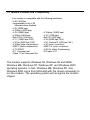
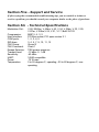
V.90 (V.92 Upgradeable)
56K PCI Modem
User’s Guide
Notice: The manufacturer reserves the right to make improvements to the product
described in this manual at any time and without notice.
All trademarks mentioned in this document are the property of their respective
owners.
©2001 This document is copyrighted. All rights are reserved. This document may not, in
whole or part, be copied, photocopied, reproduced, translated, or reduced to any
electronic medium or machine-readable form without prior consent, in writing, from the
manufacturer.
Second Edition, Version 2.0
Getting the Most From Your V.90 Modem
Section One - Introduction ........................................................... 4
Section Two - Installing the FAX/Modem ..................................... 6
Section Three - Troubleshooting .................................................. 9
Section Four - AT Command Set............................................... 11
Section Five - Support and Service ........................................... 13
Section Six - Technical Specifications ...................................... 13
Section Seven – Regulatory Notices.......................................... 14
Section One - Introduction
Congratulations on purchasing your 56k V.90 modem, the latest in
communication technology. Your modem represents a new
generation of PC communication peripheral devices, combining
high-speed Data and Fax functions into a single device. It supports
V.90 and K56flex technology for 56kbits/s data transfer rates. This
high performance modem connects your computer to all popular
modems and fax machines in use today. The modem uses the
Lucent chipset and standard Lucent LT Winmodem software drivers
for the highest level of compatibility.
1.1 How Does V.90 Work
V.90 technology allows users to receive data from their Internet
Service Provider (ISP) at data rates up to 56kbps. To make use of
this capability, your ISP must support either the V.90 or the K56flex
standard.
1.2 Benefits of V.90 56k Communications
For serious Internet users the increase in speed is dramatic,
because the information that usually makes you wait – graphicsheavy Web pages, sound, video, and other large files – now
downloads to your computer twice as fast as with previous speed
standards. Upstream transmissions (mostly keystroke and mouse
commands from your computer, which require less bandwidth)
continue to flow quickly at the conventional rate of 33.6Kbps.
1.3 Modem Features and Compatibility
Your modem is compatible with the following standards.
• V.90 / K56flex
• Upgradeable to the V.92
standard when finalized
• V.32 (9600 bps)
• V.32bis (14400 bps)
• V.34 (28800 bps)
• V.22bis (2400 bps)
• Bell 212A (1200 bps)
• V.17 (14400 bps FAX)
• V.27ter (4800 bps FAX)
• V.42bis (data compression)
• MNP 5 (data compression)
• V.70 DSVD
• AT Command set
• Class 1 Fax Command Set
• V.34plus (33600 bps)
• V.22 (1200 bps)
• Bell 103 (300 bps)
• V.29 (9600 bps FAX)
• V.21 Channel 2 (300 bps FAX )
• V.42 (error correction)
• MNP 2-4 (error correction)
• V.80 for Video Conferencing
• PCI spec V2.1
The modem supports Windows 95, Windows 98 and 98SE,
Windows ME, Windows NT, Windows XP, and Windows 2000
operating systems. In fact, Windows ME, Windows XP, and
Windows 2000 come from Microsoft with the drivers necessary to
run the modem. The operating system will recognize the modem
chipset
Section Two - Installing the FAX/Modem
2.1 PCI Modem Installation
Your modem may have come pre-installed in your new computer. If
so, you may skip this section.
CAUTION: Before removing the cover from your computer, turn off
and unplug the computer and all attached external peripherals. Prior
to removing the modem from its antistatic bag, discharge any static
electricity from your body by touching the power supply or the
chassis of the computer before removing the modem from its antistatic bag.
1. Turn off the computer and unplug it from the AC outlet.
2. Remove the computer's cover, in accordance to its owner's
manual.
3. Select any available PCI bus slot.
4. Unscrew and remove the slot cover. Set the screw aside for later
use.
5. Carefully insert the modem into the selected slot. Apply even
pressure until the modem is firmly seated.
6. Secure the bracket with the screw saved earlier.
7. Replace the computer cover and plug in your computer.
Reconnect all cables.
8. Connect the telephone cable into either phone cable connector
on the back of the modem. Attach the other end into the
telephone wall jack.
2.2 Communication Port and Interrupt Settings
The modem requires a communications (COM) port to communicate
with the computer system. Most computers are equipped with one or
more COM ports on the rear panel. Your modem does not connect
to these COM ports, but connects to the internal expansion bus on
your computer. The internal modem will therefore be assigned its
own COM port number. Your modem supports Plug and Play (PnP),
which allows the COM port and IRQ settings to be automatically
assigned by the computer and the operating system.
2.3 Installing the Modem in Windows
The modem is compatible with all Windows desktop Operating
systems from Windows 95 to the present, including:
-
Windows 95 OSR2
Windows 98
Windows 98SE
Windows ME
Windows NT versions 4 and 5
Windows 2000
Windows XP
The installation procedure is the the same for all versions of
Windows.
After physically installing the modem into the computer, when the
computer is first turned on, Windows will automatically recognize
the new modem and will ask if you want to install software drivers
for the new device.
For Windows ME, Windows 2000, and Windows XP, the operating
system will install drivers that are already included with Windows.
No additional drivers are required.
For other versions of Windows, you will need a driver installation
disk. When Windows identifies the new hardware and asks for a
driver disk, select ‘Cancel’ to terminate the Windows ‘new hardware
installation’ procedure. Windows will stop the installation procedure
and boot normally.
After Windows has finished startup, insert the diskette included with
the modem. From the Start Menu, select ‘Run’ and type
“a:\setup.exe”.
To verify the modem was configured properly, go to the Windows
START button, select the SETTINGS option, then select CONTROL
PANEL. Double-click the MODEMS icon. You should see your new
modem listed in the GENERAL tab of the Modem Properties
window. Next, click on the DIAGNOSTICS tab of the Modem
Properties window. Find your new modem in the list of installed
modems and highlight the port the modem has been assigned to.
Now click on the More Info... button. This will show a window with
information about your modem and your configuration.
Please consult "Section Three: Troubleshooting" if you encounter
any difficulties.
2.5 Testing the Modem
To confirm that the modem is working properly after installation, run
a modem communication program and set the software for the
correct modem COM port. COM port setting information can be
found in the Modem Control panel of your Windows operating
system. To verify your software is communicating properly with
your modem, at the software's terminal mode prompt, type AT
followed by the ENTER key. The modem should respond by
displaying OK. The OK response indicates that the modem is
working properly. If the modem does not return the proper response,
refer to Section 3 for troubleshooting information.
Section Three - Troubleshooting
Your modem is designed to provide reliable and trouble-free functionality. However,
should you experience any difficulty, the information contained in this section will
assist you in determining and resolving the source of the problem. If you can not
resolve your situation after reading this chapter, contact your dealer or vendor for
assistance.
3.1 Modem does not respond to commands.
1. Make sure the modem is not configured with a conflicting COM port and IRQ setting.
Check for conflicts by going to the SYSTEM control panel and selecting the Device
Manager tab. Then, double-click on the modem icon to get a listing of modems that
are installed on your computer. Double-click on the listing for your new modem. This
will show you the modem’s properties. If Windows configured the modem correctly,
the section labeled “Device status” should read “This device is working properly.” If
this is not the case, you might have a hardware resource conflict. To correct this,
click on the Resources tab to view and manually change your configuration to avoid
the conflict.
2. Make sure the modem is properly initialized by the communication software. Your
modem may have been improperly initialized by the software because you have
selected an incorrect modem type. Select "Lucent Based Data/Fax/Voice/DSVD
Modem" in your application software. Alternatively, you should use the “Generic
Hayes Modem” option for data-only applications. You may also be prompted to enter
an initialization string” by the software. Use AT&F as your initialization string.
3.2 Modem dials but does not connect.
1. Make sure the phone line is working properly. A noisy line will prevent proper
modem operation.
2. Try connecting to another modem number to ensure the problem is not related
to the answering modem.
3.3 Modem makes a connection but no data appears on your
screen.
1. Make sure all communication parameters (baud rate, data, stop, and parity bits) are
properly configured and are identical on both sides. Be certain hardware flow control
(RTS/CTS - default) is enabled in both the modem and the communication software.
2. Press the ENTER key several times. The remote system may be waiting to receive
your data before it begins.
3. Make sure the correct terminal emulation mode is being used in the software (refer to
software manual).
3.4 Modem experiences errors while on-line with a remote
modem.
1. Make sure Call Waiting is turned off.
2. Make sure RTS/CTS hardware flow control is enabled (do not use XON/XOFF
software flow control when transferring binary files).
Section Four - AT Command Set
4.1 Executing Commands
Your modem is in Command Mode upon power-on and is ready to receive and
execute “AT" commands. The modem remains in Command Mode until it makes a
connection with a remote modem.
4.2 AT Commands & Format
All commands must begin with the AT prefix, followed by the command letter and
ended with the ENTER key. All default settings are printed in bold text. Spaces are
allowed in the command string to increase command line readability but are ignored
by the modem during command execution. All commands may be typed in either
upper or lower case, but not mixed. A command issued without any parameters is
considered as specifying the same command with a parameter of “0”.
Example:
ATL [ENTER]
This command causes your modem to lower its speaker volume.
All default settings are printed in bold text.
Command
A
A/
B0
B1
Dn
Function
E0
E1
+++
Answer incoming call
Repeat last command. Do not precede A/ with AT or follow with ENTER
CCITT mode @ 1200 bps
Bell mode @ 300/1200 bps
0 - 9, A-D, # and *
L last number redial
P pulse dial
T tone dial
W wait for second dial tone
,
pause
@ wait for five seconds of silence
!
flash
;
return to Command Mode after dialing
$ wait for AT&T "bong" tone
Echo disabled
Echo enabled
switch from Data mode to Command Mode
H0
H1
I0
I1
I2
I3
Modem goes on-hook
Modem goes off-hook
Returns default speed and controller firmware version
ROM Check sum code
ROM test
Returns default speed and controller firmware version
I9
L0
L1
L2
L3
M0
M1
M2
M3
O0
O1
P
Q0
Q1
T
V0
V1
Y0
Z0
Z1
&F
&M0
&S0
&S1
Returns country code
Low speaker volume
Low speaker volume
Medium speaker volume
High speaker volume
Speaker always off
Speaker on until carrier detected
Speaker always on
Speaker off during dialing, on until carrier detected
Return online to Data Mode
Issue a retrain before returning to Data Mode
Pulse dial
Result codes enabled
Result codes disabled
Tone Dial
Display result codes as digits
Display result codes as text
Disable long space disconnect
Reset & recall user profile 0
Reset & recall user profile 1
Load factory default configuration
Asynchronous mode operation
DSR always ON
DSR comes on when establishing a connection and goes off when the connection
ends
&V
View Active profile
&W0 Store active profile as Profile 0
&Y0
Select Profile 0 upon Power on or reset
&Zn=x Store phone number x into non-volatile RAM, n=0-3
\N0
Buffer mode, no error control
\N1
Direct mode
\N2
MNP reliable mode
\N3
V.42, MNP, or buffer mode (autoreliable mode)
\N4
V.42 mode or disconnect
\Q0
Disable flow control
\Q1
XON/XOFF software flow control
\Q3
RTS/CTS hardware flow control
\Tn
Inactivity timer, n=0-255
\V0
Disable protocol result code appended to DCE speed
\V1
Enable protocol result code appended to DCE speed
Section Five - Support and Service
If after trying the recommended troubleshooting tips, you are unable to isolate or
resolve a problem, you should consult your computer dealer or the place of purchase.
Section Six - Technical Specifications
Modulation Std.:
Compression:
Host Interface:
COM ports:
IRQ lines:
FAX Group:
FAX Command:
V.90, K56flex, V.42bis, V.42, V.34, V.32bis, V.32, V.29,
V.27ter, V.22bis,V.22, V.21, V.17, Bell212/103
MNP 5, 4, 3, 2
PCI Bus socket, PCI spec version 2.1
1, 2, 3, 4, 5
3, 4, 5, 7, 9, 10, 11, 12
Group III
Class 1
Escape Detection:
TIES escape sequence
Transmit level:
Sensitivity:
UART:
Power:
Temperature:
-12 dBm +/- 1 dB
-43 dBm
16550 compatible
.75 W max
0 to 55 degrees C, operating; -20 to 80 degrees C, nonoperating
Section Seven – Regulatory Notices
FCC Compliance
This equipment complies with Part 68 of the FCC Rules. On this equipment is
a label that contains, among other information, the FCC registration number and Ringer
Equivalence Number (REN) for this equipment. You must, upon request, provide this
information to your telephone company.
If your telephone equipment causes harm to the telephone network, the
Telephone Company may discontinue your service temporarily. If possible, they will notify
in advance. But, if advance notice isn’t practical, you will be notified as soon as possible.
You will be informed of your right to file a complaint with the FCC.
Your telephone company may make changes in its facilities, equipment,
operations, or procedures that could affect proper operation of your equipment. If they do,
you will be notified in advance to give you an opportunity to maintain uninterrupted
telephone service. The FCC prohibits this equipment to be connected to party lines or
coin-telephone service.
In the event that this equipment should fail to operate properly, disconnect the
equipment from the phone line to determine if it is causing the problem. If the problem is
with the equipment, discontinue use and contact your dealer or vendor.
FCC Class B Statement
This equipment has been tested and found to comply with the limits for a Class B
digital device, pursuant to Part 15 of the FCC Rules. These limits are designed to provide
reasonable protection against harmful interference in a residential installation. This
equipment generates, uses and can radiate radio frequency energy, and if not installed
and used in accordance with the instructions, may cause harmful interference to radio
communications. However, there is no guarantee that interference will not occur in a
particular installation. If this equipment does cause harmful interference to radio or
television reception, which can be determined by turning the equipment off and on, the
user is encouraged to try to correct the interference by one or more of the following
measures:
•
Reorient or relocate the receiving antenna
•
Increase the separation between the equipment and the receiver
•
Connect the equipment into an outlet on a circuit different from that to
which the receiver is connected
•
Consult the dealer or an experienced radio / TV technician for help
Notice: 1) Shielded cables, if any, must be used in order to comply with the emission
limits. 2) Any change or modification not expressly approved by the Grantee of the
equipment authorization could void the user’s authority to operate the equipment.
FCC Fax Branding Statement
The Telephone Consumer Protection Act of 1991 makes it unlawful for any person to use
a computer or other electronic device, including fax machines, to send any message
unless such message clearly contains in a margin at the top or bottom of each
transmitted page or on the first page of the transmission, the date and time it is sent and
an identification of the business or other entity, or other individual sending the message
and the telephone number of the sending machine, or such business, other entity, or
individual. (The telephone number provided may not be a 900 number or any other
number for which charges exceed local or long-distance transmission charges.)
In order to program this information into your fax machine or fax/modem consult your fax
machine user’s manual or software user’s manual for setup instructions.
DOC Compliance Information
NOTICE: The Canadian Department of Communications label identifies certified
equipment. This certification means that the equipment meets certain
telecommunications network protective, operational and safety requirements. The
Department does not guarantee the equipment will operate to the user’s satisfaction.
Before installing this equipment, users ensure that it is permissible to be
connected to the facilities of the local telecommunications company. The equipment must
also be installed using an acceptable method of connection. The customer should be
aware that compliance with the above conditions may not prevent degradation of service
in some situations.
Repairs to certified equipment should be made by an authorized Canadian
maintenance facility designated by the supplier. Any repairs or alterations made by the
user to this equipment, or equipment malfunctions, may give the telecommunications
company cause to request the user to disconnect the equipment.
Users should ensure for their own protection that the electrical ground
connections of the power utility, telephone lines and internal metallic water pipe system, if
present, are connected together. This precaution may be particularly important in rural
areas.
CAUTION: Users should not attempt to make such connections themselves, but should
contact the appropriate electric inspection authority, or electrician, as appropriate.
NOTICE: The Load Number (LN) assigned to each terminal device denotes the
percentage of the total load to be connected to a telephone loop which is used by the
device, to prevent overloading. The termination on a loop may consist of any combination
of devices subject only to the requirement that the sum of the Load Numbers of all the
devices does not exceed 100.
UL/CUL Statement
This equipment is to be used only with a UL listed equipment.