1
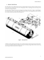
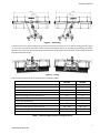
ROTARY BROOM HT2500, HT3000 MEIREN ENGINEERING OÜ VÄIKE MÄNNIKU 7/// TALLINN 11216 /// ESTONIA/// PHONE +372 682 5002 /// FAX: +372 610 0589 /// E-MAIL: [email protected] /// WWW.MEIRENSNOW.COM USER MANUAL 2015 ROTARY BROOM HT CONTENT TABLES ............................................................................................................................................................... 2 FIGURES ............................................................................................................................................................. 2 CE DECLARATION OF CONFORMITY ..................................................................................................................... 4 FOREWORD ........................................................................................................................................................ 5 GENERAL SAFETY REQUIREMENTS ..................................................................................................................... 5 PERSONNEL ....................................................................................................................................................... 5 1. PRODUCT DESCRIPTION............................................................................................................................. 6 1.1 ROTARY BROOM IN STANDARD EQUIPMENT ................................................................................................................... 8 1.2 ACCESSORY EQUIPMENT ............................................................................................................................................ 8 2. SAFETY REQUIREMENTS FOR OPERATING THE BROOM .............................................................................. 8 3. MOUNTING AND DEMOUNTING THE ROTARY BROOM .................................................................................. 9 3.1. MOUNTING OF A ROTARY BROOM ............................................................................................................................ 9 3.1.1. 3.1.2. 3.1.3. 3.1.4. 3.2. 4. HYDRAULIC FLOAT ............................................................................................................................................. 14 VERTICAL SETTING OF THE FRONT SECTION OF THE BRUSH ........................................................................................ 15 LATERAL INCLINE OF THE BRUSH AND ITS LOCKING ................................................................................................. 16 ADJUSTING UNIFORM WEAR OF THE BRISTLES ........................................................................................................ 17 REPLACING SPINDLE AND BRISTLES ..................................................................................................................... 20 POSITION OF FRONT PLASTIC SHEET OF THE BROOM................................................................................................. 21 USE OF INJECTORS ............................................................................................................................................ 21 MAINTENANCE ......................................................................................................................................... 23 5.1. 6. STORAGE OF THE BRUSH ..................................................................................................................................... 13 USING THE BRUSH ................................................................................................................................... 14 4.1. 4.2. 4.3. 4.4. 4.5. 4.6. 4.7. 5. Mounting of the rotary broom on the vehicle ...................................................................................... 9 Demounting the rotary broom from a vehicle ................................................................................... 11 Mounting of a rotary broom on a tractor ............................................................................................ 12 Demounting the rotary broom from a tractor.................................................................................... 13 GREASE POINTS ................................................................................................................................................ 24 WARRANTY CONDITIONS .......................................................................................................................... 25 TABLES Table 1 –Technical specifications of rotary broom HT .............................................................................................. 7 FIGURES Figure 1 – Rotary broom HT ........................................................................................................................................... 6 Figure 2 – Sidesifting...................................................................................................................................................... 7 Figure 3 – Tilting .............................................................................................................................................................. 7 2 WWW.MEIRENSNOW.COM ROTARY BROOM HT Figure 4 – Safety marking: RISK OF ACCIDENT! ........................................................................................................... 9 Figure 5 – Mounting the rotary broom on a vehicle ................................................................................................. 10 Figure 6 – Working positions for support legs .......................................................................................................... 11 Figure 7 – Mounting the rotary broom on a tractor ................................................................................................. 12 Figure 8 – Working position of the support legs. ...................................................................................................... 13 Figure 9 – Hydraulic components of lifting cylinder ............................................................................................... 15 Figure 10 – Disconnection of the parallelogram bar ............................................................................................... 16 Figure 11 – Locking the front section of the brush ................................................................................................. 17 Figure 12 – Adjusting the tension of leaf springs .................................................................................................... 18 Figure 13 – Adjusting leaf springs downwards ........................................................................................................ 19 Figure 14 – Adjusting leaf springs upwards ............................................................................................................. 19 Figure 15 – Removal of spindle and bristles ............................................................................................................ 20 Figure 16 – Front sheet of the brush up .................................................................................................................... 21 Figure 17 – Angle of injectors in relation to horizontal ........................................................................................... 22 Figure 18 – Injector’s control ...................................................................................................................................... 22 Figure 19 – Grease points ........................................................................................................................................... 24 3 WWW.MEIRENSNOW.COM ROTARY BROOM HT CE DECLARATION OF CONFORMITY Manufacturer: Meiren Engineering OÜ Väike-Männiku 7 11216 Tallinn Phone +372 682 5002 www.meirensnow.com We hereby declare that the below mentioned product: Rotary broom HT Model: ............................................ Serial number: ............................................ Manufacturing date: ............................................ Meets the following directives and standards: 2006/42/EC EN 349:1993+A1:2008 4 WWW.MEIRENSNOW.COM ROTARY BROOM HT FOREWORD Thank you for choosing the Meiren Snow product. This operator manual consists of technical specifications, user and maintenance instructions and warranty terms and conditions of HT series rotary broom. HT series rotary brushes are designed for removing dust, sand, gravel and loose snow from surfaced roads. Using the sweeper contrary to its intended purpose may cause economic losses and bodily injuries. It is therefore of the utmost importance that the person operating the brush read through the manual and use the product pursuant to the requirements. Any misuse of the product releases the manufacturer from the liability for occurred damages and for reimbursing losses. GENERAL SAFETY REQUIREMENTS As the construction of the product is complex and it contains moving parts, it is very important that the person working with the equipment be aware of all the safety risks. To reduce the risks, it is important that the operator have read through the operator manual; the operator have been completed an appropriate training, which gives him/her the permit to use a product of this type in his/her work; the operator have been provided with all necessary tools and is wearing appropriate work clothes. PERSONNEL This product may only be used and maintained by properly trained personnel. The operator’s employer is obliged to ensure fulfilment of all user instructions and safety requirements set out by the manufacturer. Please read carefully through the operator’s manual before starting working with the rotary broom. 5 WWW.MEIRENSNOW.COM ROTARY BROOM HT 1. PRODUCT DESCRIPTION The rotary broom HT is a flexible device that can be used throughout the year to clean the roads. The rotary brush HT is foremost designed for use on free- and highways, also in car parking areas; if necessary also at road works brushing loose gravel. The rotary broom HT (Figure 1) has the mounting plate according to the vehicle (1, Figure 1), parallelogram (2), fore part of the brush (3) and support legs (4). As an extra, broom can be equipped with water reservoirs (5), an electrical water pump (6) and nozzle system (7). Figure 1 – Rotary broom HT In addition to raising, lowering and rotating (± 30 ° in relation to the front of the car) the fore part of the broom, it can also be shifted to the left and to the right side (Figure 2). Sideways tilting enables smooth manoeuvring and moving over different obstacles on the ground. 6 WWW.MEIRENSNOW.COM ROTARY BROOM HT Figure 2 – Sidesifting Lateral incline of the brush enables to tilt the front section of the brush ±3° in relation to the ground (Figure 3). This ensures smooth and even contact of the bristles with uneven or inclined ground during operation, which in turn will ensure better operating result and more uniform wear of the bristles. If necessary the incline can be locked with the pin. Figure 3 – Tilting General specification for the HT rotary broom is listed in Table 1 Overall width, mm Overall height, mm Brush internal diameter, mm Min operational width, mm Max turning angle (in both directions), ° Side shift, mm Tilt (in both directions), ° Weight with standard equipment, kg Recommended hydraulic pressure, bar Recommended hydraulic flow rate, l/min Recommended capacity for water pump, l/min HT2500 2440 915 254 2115 30 930 3 500 160...200 60...100 20 HT3000 2960 915 254 2500 30 930 3 545 160...200 60...100 20 Table 1 - Technical specifications of rotary broom HT 7 WWW.MEIRENSNOW.COM ROTARY BROOM HT 1.1 Rotary broom in standard equipment Mounting plate according to the vehicle Parallelogram Fore part of the broom Support legs Safety markings Colors: yellow, RAL 1007; black, RAL 9005 1.2 Accessory equipment Brushes (internal diameter 254 mm; external diameter 915 mm) Water reservoirs (2x140 L) Electrical water pump Water couplings and nozzles 2. SAFETY REQUIREMENTS FOR OPERATING THE BROOM Before operating the brush Check the integrity and technical condition of the rotary broom. It is prohibited to commence work with a device that is not in good technical condition. Check that there are no people or objects near the rotary broom that the brush might injure or damage. In addition, safety of people carrying out maintenance of the rotary brush, repairing the device or moving it with the help of hydraulics or any other lifting mechanism has to be ensured. Failure to follow safety requirements may result in causing injuries to people (the brush is provided with safety markings, see figure 5). It is prohibited to work under a lifted rotary broom, if the brush is not supported. Check that the rotary broom is properly fastened to the vehicle and the fasteners are not damaged. Check the condition and visibility of safety marking, position lamps (if available) and reflex reflectors. Check the fasteners of levers and cylinders. Check that the hydraulic hoses are intact and properly fastened. Check that the rotary broom is properly greased. Check that the rotary broom has no damages. Working with the brush The rotary broom may only be used by a person, who is at least 18 years of age, holds a driver's license in the respective category and has familiarised himself/herself with the operator’s manual of the highway sweeper. Make sure to always pay attention to the surrounding area and other traffic, including vehicles approaching from side roads and behind. Pay attention to pedestrians and cyclists, so as not to put them in danger while working with the brush. All warning lights must be switched on at all times while working! Adhere to general traffic regulations. The maximum operating speed for the rotary broom in normal road conditions on hard-paved roads is 50 km/h. It is prohibited to brush near people and devices; that the brush might injure or damage. It is prohibited to attach such accessory equipment to the movable parts of the rotary brush that the 8 WWW.MEIRENSNOW.COM ROTARY BROOM HT manufacturer has not approved. It is prohibited to use hydraulically operating devices as lifting jack. The rotary broom may only be lifted from lifting eyes. Stop the work with a brush if the excessive vibration occurs and try to identify and eliminate the cause of the vibration. ATTENTION! Pay extra attention when cleaning crossings. Avoid unnecessary backing. If possible, avoid street cleaning in heavily loaded crossings and roads during peak hours. During working the safety signs shall always be switched on! Each time there is an incident during operation that may damage the equipment, an inspection of the equipment shall be arranged in order to detect and assess possible damages. Damages (cracks in the structure or welded joints, deformed parts) may put property and people's health in danger. It is prohibited to continue work until the damages are repaired. Figure 4 – Safety marking: RISK OF ACCIDENT! 3. MOUNTING AND DEMOUNTING THE ROTARY BROOM 3.1. Mounting of a rotary broom 3.1.1. Mounting of the rotary broom on the vehicle Mounting shall be performed on a level surface! Drive the vehicle as close to the mounting frame (1, Figure 5) of the broom in the parking position (Figure 5) as possible and connect the hydraulic hoses to the vehicle's quick coupling. Use the lifting cylinder (6) to lift the mounting frame of the brush to such a height that the fastening eyes (2) are over the upper edge of the mounting frame of the vehicle. Guide the vehicle frame next to the broom frame and use the lifting cylinder to lower the connection frame of the brush to the upper edge of the mounting frame of the vehicle. Check that the connection ears are in correct positions and lock the broom mounting frame to the vehicle frame (different countries use different systems to lock the rotary broom – adhere to the prescribed system). Lift the fore part (3) of the rotary broom, lift the support legs (4) attached to the mounting frame higher and turn over the support legs (5) attached to the fore part of the brush, as shown on figure 6. 9 WWW.MEIRENSNOW.COM ROTARY BROOM HT Figure 5 – Mounting the rotary broom on a vehicle 10 WWW.MEIRENSNOW.COM ROTARY BROOM HT Figure 6 – Working positions for support legs 3.1.2. Demounting the rotary broom from a vehicle Mounting shall be performed on a level surface! Lift up the fore part of the brush (3, Figure 5) and lower down the support legs (5) into the parking position, as shown on figure 5. Lower the fore part of the rotary broom so, that the fore part would fall back on the supporting legs. Disconnect the mounting frame (1) of the rotary broom off the mounting frame of a vehicle. Lift the mounting frame of the broom off the mounting frame of the vehicle with the help of the lifting cylinder (6). Slightly back away from the brush by vehicle. Lower the mounting frame of the broom so that the mounting frame would fall back on the supporting legs. Disconnect the hoses and drive further. 11 WWW.MEIRENSNOW.COM ROTARY BROOM HT 3.1.3. Mounting of a rotary broom on a tractor Mounting shall be performed on a level surface! Drive the tractor as close to the mounting frame (1, Figure 7) of the broom in the parking position (Figure 7) as possible and connect the hydraulic hoses to the tractor quick coupling. Guide the tractor mounting frame next to the broom frame and lift the first frame so that the fastening eyes (2) are over the upper edge of the mounting frame of the tractor. Check that the connection ears are in correct positions and lock the broom mounting frame to the tractor frame (different countries use different systems to lock the rotary broom – adhere to the prescribed system). Lift the support legs (4) attached to the mounting frame and the fore part (3) of the rotary broom, higher and turn over the support legs (4) attached to the fore part of the brush, as shown on figure 8. Figure 7 – Mounting the rotary broom on a tractor 12 WWW.MEIRENSNOW.COM ROTARY BROOM HT Figure 8 – Working position of the support legs. 3.1.4. Demounting the rotary broom from a tractor 3.2. Mounting shall be performed on a level surface! Lift up the fore part of the brush and lower down the support legs (4, Figure 7) into the parking position, as shown on Figure 7. Lower the broom and disconnect the locking of the mounting frame (1) of the brush off the mounting frame of the tractor. Lower the mounting frame of the tractor so that it could easily part off the mounting frame of the broom. Disconnect the hoses and drive further Storage of the brush When the brush is not in use, it shall be stored in parking position, as shown on Figure 5 and Figure 7. In this position, cylinders of support legs are adjusted to the lowest position. Before cold season remove the injector system and electrical water pump (6 and 7, Figure 1), in order to avoid freezing of water and damaging the equipment. 13 WWW.MEIRENSNOW.COM ROTARY BROOM HT 4. USING THE BRUSH Rotary broom HT offers to the user various possibilities for efficient and sustainable cleaning of roads. The description below provides overview of major properties of the brush and guidelines, how to use the product and which instructions should be followed, in order to ensure long service life and good operating result. 4.1. Hydraulic float Lifting cylinder of the brush can operate in two modes: Lifting cylinder can be freely moved in both directions (necessary during installation, removal or parking of the brush). Operating position with hydraulic float (necessary during operation of the brush, ensuring lower contact pressure of the bristles on the ground and adaptation to irregularities of road surface). Modes can be changed with manual lever (1, Figure 9). Hydraulic float of the brush ensures that during operation of the brush bristles are not pressed too strongly against the ground, which would cause excessive wear of bristles. Furthermore, hydraulic float enables to adapt to irregularities of road surface and ensure better operating result. To prevent too strong pressure of the bristles on the ground and resulting warping of bristles, counterpressure is maintained in the lifting cylinder of the brush. With the pressure, the lifting cylinder will try to lift bristles lightly. This pressure can be controlled with pressure regulator (2, Figure 9). Higher pressure ensures lower contact pressure of the bristles on the ground, suitable e.g. for brushing of dust. If the work requires higher contact pressure of the bristles (e.g. brushing of crushed stones), oil pressure can be lowered. Pressure of the lifting cylinder can be read on the pressure gauge (3, Figure 9). Hydraulic battery of the lifting cylinder enables hydraulic float of the brush, in order to improve operating result on uneven road. When the brush is used on a tractor, lifting cylinder of the brush should be used for lifting and lowering of the brush during brushing instead on lifting equipment of the tractor. This ensures correct contact pressure of the bristles on the ground and float of bristles. Depending on the hydraulic circuit of the vehicle, it may be necessary to stop rotation of the bristles in order to lower the brush. 14 WWW.MEIRENSNOW.COM ROTARY BROOM HT Figure 9 – Hydraulic components of lifting cylinder 4.2. Vertical setting of the front section of the brush It is possible to adjust the length of bar of the parallelogram of the brush. This is necessary, if mounting frame of the vehicle is not perpendicular to the ground and thus also the front section of the brush is not vertical – bristles will wear unevenly. For vertical adjustment of the fore part of the brush, first the vertical section of a brush fixed to the vehicle shall be lifted with lifting cylinder to such height that bristles do not touch the ground. After this, the fore part of the brush shall be supported by a lift or a telpher. Then remove the upper axle (2) of the bar of the parallelogram (1, Figure 10), distance bushes (3), washer (4) and round split pin (5). Now the threaded end of the bar can be turned inwards or outwards, changing correspondingly total length of the bar and position of the front section of the brush. If correct length of the bar is achieved, it shall be fixed again with axle, distance bushes and fixing details. 15 WWW.MEIRENSNOW.COM ROTARY BROOM HT Figure 10 – Disconnection of the parallelogram bar 4.3. Lateral incline of the brush and its locking Lateral incline of the brush enables to tilt the front section of the brush ±3° in relation to the ground (Figure 3). This ensures smooth and even contact of the bristles with uneven or inclined ground during operation, which in turn will ensure better operating result and more uniform wear of the bristles. Incline can be locked with the pin (1, Figure 11). Locking is necessary e.g. in case of a longer travel, when the brush is not operated. Locked (A) and unlocked (B) front section of the brush is shown on Figure 11. 16 WWW.MEIRENSNOW.COM ROTARY BROOM HT Figure 11 – Locking the front section of the brush 4.4. Adjusting uniform wear of the bristles In order to ensure uniform wear of the bristles, it may be necessary to adjust leaf springs of lateral incline. In result of this, the bristles in right or left end of the front section of the brush will achieve lower contact pressure on the ground and consequently lower wear. This may be necessary, when upon brushing to one side a pile of sand, gravel etc. forms in front of the bristles, wearing the bristles of one end faster than in the other end. Tension of leaf springs (1, Figure 12) can be adjusted by lifting or lowering the adjustment plate (2). 17 WWW.MEIRENSNOW.COM ROTARY BROOM HT Figure 12 – Adjusting the tension of leaf springs Adjustment of leaf springs (1, Figure 13) downwards will decrease wear of the left bristles (2), when looking the brush from the front. Figure 13 shows the brush from the front, where leaf springs (1, Figure 14) are adjusted upwards, decreasing the wear of the right bristles (2). 18 WWW.MEIRENSNOW.COM ROTARY BROOM HT Figure 13 – Adjusting leaf springs downwards Figure 14 – Adjusting leaf springs upwards 19 WWW.MEIRENSNOW.COM ROTARY BROOM HT 4.5. Replacing spindle and bristles Bristles are details wearing during operation, which need to be replaced. Bristles are located on the brush spindle. To replace the spindle and/or the bristles, motor holder (1, Figure 15) shall remove from one end of the brush. Now the spindle (4) can be removed with bristles. To remove bristles from the spindle, remove the locking disc (2). When re-installing bristles and/spindle to the brush, check visually before replacement of motor holder that radial bolts of the clutch (5) are correctly fixed and re-fix them with strong thread glue, if necessary. Figure 15 – Removal of spindle and bristles The number of bristles in case of this product shall be over 60 bristles. Otherwise hydraulic float of the brush is impaired. 20 WWW.MEIRENSNOW.COM ROTARY BROOM HT 4.6. Position of front plastic sheet of the broom In the fore part of the broom there are two plastic sheets, of which the front sheet has two possible positions. The front sheet is adjusted low for operating in normal conditions (brushing dust, sand, crushed stone etc.). The second, upper position of the sheet is necessary when brushing snow, to prevent jamming of bristles with snow. Front sheet adjusted up is shown on figure 16. Figure 16 – Front sheet of the brush up 4.7. Use of injectors The injector system is used to reduce dust in front of the broom during operation. Angle of injectors in relation to horizontal shall be approximately 15° (Figure 17). In such case the angle of water jet from injectors is most efficient for binding the volatile dust. NB! Use only pure water in the injector system. 21 WWW.MEIRENSNOW.COM ROTARY BROOM HT Figure 17 – Angle of injectors in relation to horizontal In addition to correct angle of injector it is also important to monitor the condition of injectors. If any injector is dripping after water pressure is stopped, its valve (1, Figure 18) shall be unscrewed in order to see, if the seal is damaged or any dirt has entered between the valve and the seal (and to remove the dirt), and retighten the valve. Similar check is necessary also for the injector end (2), if it seems that the sprayed jet is uneven. Figure 18 – Injector’s control 22 WWW.MEIRENSNOW.COM ROTARY BROOM HT 5. MAINTENANCE MAINTENANCE AFTER 8 OPERATING HOURS Check all bolt connections and hydraulics connections and tighten, if necessary. Check that there are no leaks in the hydraulic system. If necessary, tighten the fastenings of hydraulic parts and hose ends. MAINTENANCE AFTER EVERY 150 OPERATING HOURS POST-SEASON MAINTENANCE Check all bolt connections and Check all bolt connections and tighten, if necessary. tighten, if necessary. Lubricate all lubrication areas: grease nipples are on the lifting and tilting cylinder, on the rod of parallelogram, and on the axle of rotation beam, tilting axle and rotation axle. Check that there are no leaks in the hydraulic system. If necessary, tighten the fastenings of hydraulic parts and hose ends. Check the condition and fastenings Visually check the fastening bolts of Spray the rotary broom’s zinc parts, of the bristles. If necessary, adjust or the clutch and if necessary tighten hydraulic valves and hose ends with replace the bristles. the loose bolts by thread-locking preserving wax. glue. Clean the nozzles and nozzle flaps. X X X X X X X X X Lubricate all lubrication areas. Also lubricate or wax the extending adjusting surfaces of the inner bar of the sliding soleplate and wheel mechanism. Visually check the rotary broom and identify any parts that require replacing. Repair all paint damages. Pull in the cylinder's piston rod or conserve it with an appropriate lubricant. Keep the rotary broom in a place that is open to the winds but protected against rain and sun. 23 WWW.MEIRENSNOW.COM ROTARY BROOM HT 5.1. Grease points Figure 19 – Grease points Pos. nr 1 2 3 4 5 6 Location Tilt hinge Lift cylinder Axle Flanged axle Sift cylinder Rod In all Quantity 2 2 4 1 2 2 13 24 WWW.MEIRENSNOW.COM ROTARY BROOM HT 6. WARRANTY CONDITIONS The Seller gives the Product a guarantee for a term of 12 (twelve) months. The guarantee term starts upon delivery of the Product to the Buyer and the time of delivery is the date indicated in the deed of delivery and receipt or CMR. The guarantee covers the elimination by the Seller of any production, material or construction defects detected in the Product or details thereof during the guarantee period. The Seller is obligated to replace the defective Product with a new one only if the repairing of the Product or a detail or replacing of a detail is not possible. The Buyer undertakes to inform the Seller in writing of any defects detected during the guarantee term within seven (7) calendar days as of learning of the defect, describing the defect in sufficient detail. The Seller is obligated to carry out an expert assessment to identify the causes of the defect within fourteen (14) working days after the receipt of the written notice. In the event of a defect covered by the guarantee the Seller eliminates it within twenty (20) working days after the expert assessment. The performance of repair work under the guarantee takes place at the delivery address specified in the Order Confirmation. Major repairs are made in the territory of the Seller. The cost of transportation of the Product to the place of guarantee repairs is borne by the Buyer. The Buyer bears the costs of repairs exceeding the terms and conditions of guarantee repairs and the transportation costs. The following defects are not covered by the guarantee: – defects arising from the natural wear and tear of the Product; – defects arising from the characteristics or damages of the road cover; – defects arising from the use of the Product in conflict with its technical conditions, security rules and purpose; – defects arising from disregarding the rules of maintenance of the Product; – defects arising from a traffic accident; – defects of which the Buyer has not informed the Seller in writing within seven (7) days as of the emergence of the defect and/or whereby the Buyer has not given the Seller the chance to identify the cause of the defect in accordance with the Agreement. – to the extent whose expansion the Buyer could have reasonably prevented. The Product guarantee term terminates before the prescribed time as of the time when: – the Product has been independently repaired, without coordinating it with the Seller in writing beforehand; – the constructions of the Product have been changed, additional equipment has and/or spare parts have been installed without coordinating it with the Seller in writing in advance. If the Seller, in spite of repeated written inquiries by the Buyer, fails to perform its guarantee obligations arising from the Agreement, the Buyer shall have the right to eliminate the Product's defect at the Seller's expense. The Buyer must inform the Seller in writing at least five (5) working days before the replacement or repairing of a defective Product and submit to the Seller a calculation of the presumable reasonable costs. The Buyer may withdraw from the Agreement and demand that the Product be taken back and the Purchase Price refunded only if the defect cannot be eliminate or the part cannot be replaced and if replacement of the defective Product with a new Product would not produce the results that would allow for the purposeful use of the Product. The Product or a part thereof replaced during the guarantee term is covered by the guarantee until the expiry of the overall guarantee term of the Product. 25 WWW.MEIRENSNOW.COM