1
US007437941B1
(12) United States Patent
(10) Patent N0.:
Ward
US 7,437,941 B1
(45) Date of Patent:
(54)
HEATING AND AIR CONDITIONING
SERVICE GAUGE
('75)
Inventor:
6,983,889 B2*
7,012,223 B2*
Oct. 21, 2008
1/2006 Alles ....................... .. 236/49.l
3/2006 Kopel ..
219/494
7,119,308 B2* 10/2006 Kopel
Charles Barry Ward’AlPhamtta’ GA
7,219,506 B2 *
(Us)
219/494
5/2007 Kang et al. .............. .. 62/176.6
OTHER PUBLICATIONS
(73) Assignee: Diversitech Corporation, Duluth, GA
(Us)
DRSA-ll00 User Manual, Digi-Cool Industries Ltd., Digital Refrig
eration System Analyzer, Copyright 2004, Digi-Cool Industries Ltd.
Web pages from WWW.digi-cool.com showing various types of refrig
( * )
Notice:
Subject to any disclaimer, the term of this
eration Products ‘lated Jul‘ 18’ 2007'
patent is extended or adjusted under 35
Datasheet regarding the DRSA-l200 Digital Refrigeration System
Analyzer, Digi-Cool Industries Ltd.
U'S'C' 154(1)) by 0 days'
DRSA-l200 User Manual, Digi-Cool Industries Ltd., Digital Refrig
eration System Analyzer, Copyright 2007, Digi-Cool Industries Ltd.
Datasheet regarding the DRSA-l000 Digital Refrigeration System
(21) Appl.No.: 11/743,374
_
(22)
_ _
_
_
Analyzer, Digi-Cool Industries Ltd.
Flled:
May 21 2007
Datasheet regarding the DRSA-l 100 Digital Refrigeration System
Analyzer, Digi-Cool Industries Ltd.
Related US. Application Data
.
_
_
_
* cited by examiner
(60) Provisional application No. 60/746,720, ?led on May
8, 2006'
Primary ExamineriAndre J. Allen
Assistant Examinerilermaine Jenkins
(51) Int. Cl.
G01L 9/00
(74) Attorney, Agent, or FirmiSmith, Gambrell & Russell
LLP
(2006.01)
(52)
as. C]. ...................................................... ..
(58)
Field of Classi?cation Search .......... .. 73/70d756
73/753
(57)
ABSTRACT
S ee app l't'
?lf
lt
hh't.
10a Ion e or Comp e e Seam
15 Dry
A pressure gauge for determining refrigerant pressure and
References Cited
refrigerant saturated Vapor equivalent temperature for a
(56)
Us‘ PATENT DOCUMENTS
6,553,777 B2 *
refrigerant in an HVAC system.
4/2003 Dillenback ................. .. 62/171
4 Claims, 1 Drawing Sheet
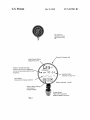
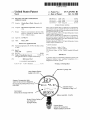
Standard 3" gauge size
Large Pressure Dispiay
Reads in PSI or KPa
Pressure / Temperature table
built-in for all common refrigerants
R12 R22 Rt 340 R4040 R4070 R4i0a
R502 R507
1.23pm
R1134 CPR-BF
Saturated Vapor
indication in deg F or C
Trend Graph
Snows rate of change over time
Battery operated - long life
Simple 3 Button Setting
Auto Power Off
Backlignt Display
Rugged Sensor
Here or NPT connection
Weather resistant connector
US. Patent
Oct. 21,2008
US 7,437,941 B1
Fig 1 (Prior Art)
Typical HVACR Gauge
with refrigerant scales in
blue.
S’rondorcl 3" gauge size
Large Pressure Displory
Reads in PSI or KPo
Pressure / Tempero’rure ‘roble
built-in for all common refrlgeronrs
Rl 2 R22 R1340 R4040 R4070 R4l 00
R502 R507
l E 3 PSI
Illllllllllllll
R 1.34
I
'
‘=1? . 3 F
a
5
'
:
:
Soruro‘red Vapor
lnollcor’rlon in deg F orC
Trencl Graph
Shows role of ohcrnge over lime
Bo?ery operoled - long life
Simple 3 Buh‘on Se?ing
Au’ro Power Off
Bookllgh’r Display
Rugged Sensor
Flore or NPT oonnec’rion
Weo’rner resislonl connector
Fig. 2
US 7,437,941 B1
1
2
HEATING AND AIR CONDITIONING
SERVICE GAUGE
The pressure gauge of the present invention includes a
sensor that measures changes in refrigerant pres sure and pro
duces an electronic pressure signal that is proportional to the
CLAIM OF PRIORITY
measured refrigerant pressure. A battery poWered micropro
This application claims priority from US. Provisional
Patent Application Ser. No. 60/746,720 ?led on May 8, 2006,
Which is incorporated herein in its entirety.
cessor Within the gauge receives the electronic pressure sig
nal, converts the electronic pressure signal to a refrigerant
pressure value in PSI or KPa, and digitally displays the refrig
erant pressure value on the face of the gauge. In addition, the
microprocessor can convert the refrigerant pres sure value to a
FIELD OF THE INVENTION
refrigerant saturated vapor equivalent temperature value (in
Fahrenheit or Celsius) for the particular refrigerant being
This invention relates to a service gauge used for installing
and servicing an HVAC system.
used in the HVAC system. Moreover, the pressure gauge of
the present invention can produce an analog trend graph
shoWing the change of refri gerant pressure or refrigerant satu
rated vapor equivalent temperature overtime in order to give
the technician a clear understanding of the operation of the
BACKGROUND OF THE INVENTION
system as the HVAC system progresses to a steady state
HVAC service personnel must measure the system refrig
condition. Further, the microprocessor can generate and dis
play a bar graph that shoWs rapid ?uctuations of the refriger
erant pressure in order to install or service a HVAC system.
This measurement is accomplished With an analog pressure
gauge. Typically, the gauges are mechanical and contain a
20
Connected to the tube are series of Watch-like gears that
connect and rotate the indicating needle located on the front
of the gauge.
Gauges can either be permanently attached to the equip
25
ment or incorporated into portable tools or manifolds. Nor
mally, a manifold or gauge manifold holds tWo gauges for
pressure measurement and includes valves for installation or
removal of the refrigerant from the HVAC system.
Further objects, features and advantages Will become
apparent upon consideration of the folloWing detailed
description of the invention When taken in conjunction With
the draWings and the appended claims.
BRIEF DESCRIPTION OF THE DRAWINGS
30
Typically, tWo gauges With different pressure ranges are
FIG. 1 is a front elevation vieW of a prior art pres sure gauge.
FIG. 2 is a front elevation vieW of a pressure gauge in
accordance With present invention.
used for the basic pressure measurements of the refrigerant.
The main analog scale of each gauge indicates pressure in PSI
(pounds per square inch) or KPa (metric Kilo-Pascals). Addi
tional inner analog scales are also printed on the face of the
gauge. The additional inner scales (circular bands of num
ant pressure that can indicate a bad compressor valve or other
system problems.
curved tube, Which bends in response to the applied pressure.
DETAILED DESCRIPTION OF THE PREFERRED
EMBODIMENT
35
bers) indicate the saturated vapor equivalent temperature for
FIG. 2 shoWs a display for an electronic pressure gauge in
different refrigerants. Because of the limited space on the
gauge face, only tWo or three different inner scales for differ
accordance With the present invention. The siZe and shape of
ent refrigerants can ?t onto the face of any one gauge. FIG. 1
40
shoWs a typical prior art pressure gauge.
The saturated vapor equivalent temperature scale of the
gauge is of importance to the technician because the saturated
vapor equivalent temperature indicated on the gauge for the
particular refrigerant is used to ascertain the temperatures in
signal that is proportional to the refrigerant pressure in the
45
parts of the system during charging, servicing, or monitoring.
50
temperature. Because HVAC systems respond very sloWly
From the refrigerant pressure value, the microprocessor
55
can calculate and render on the display a time lapsed refrig
erant pressure or a time lapsed refrigerant saturated vapor
60
other relevant information, the present invention comprises a
pressure gauge With a digital display that can display refrig
erant pressure and refrigerant saturated vapor equivalent tem
or the refrigerant saturated vapor equivalent temperature.
equivalent temperature for a preselected time period.
The pressure sensor, battery, display, and microprocessor
are contained Within the pressure gauge.
The pressure gauge of the present invention can also
With limited space on the face for printing analog scales or
perature for a large number of different refrigerants as Well as
the instantaneous or time variation of the refrigerant pres sure
can also calculate and render a bar chart of the instantaneous
refrigerant pressure on the display. Also, the microprocessor
SUMMARY OF THE INVENTION
In order to solve the problems of the prior art analog gauges
converts the electronic pressure signal to a refrigerant pres
sure value that is shoWn on the display. For a particular refrig
erant in the HVAC system, the microprocessor converts the
electronic pressure signal to a refrigerant saturated vapor
equivalent temperature value that is likeWise shoWn on of the
display.
and the pressure and the saturated vapor equivalent tempera
ture must be continuously monitored during refrigerant
charging, the use of a lookup chart is inconvenient, time
consuming, and error prone.
refrigerant line of the HVAC system. The pressure sensor is
connected to a microprocessor poWered by a battery. The
microprocessor, including related electronics and softWare,
The correct inner gauge scale must be matched to the type of
refrigerant in the system. If the gauge does not have an analog
scale that matches the refrigerant in the system being ser
viced, the technician must consult a table that converts the
pressure read on the gauge to the saturated vapor equivalent
the pressure gauge is similar to the conventional prior art
gauge shoWn in FIG. 1. The pressure gauge of the present
invention comprises a pressure sensor that is in communica
tion With a refrigerant pressure line of the HVAC system (not
shoWn). The pressure sensor produces an electronic pressure
include an external temperature probe that produces an elec
65
tronic temperature signal that is proportional to the tempera
ture sensed by the temperature probe. From the electronic
temperature signal, the microprocessor can calculate and ren
der a temperature value on the display.
US 7,437,941 B1
4
3
I claim:
Further, the pressure gauge may include an Wired or Wire
1. A pressure gauge for determining refrigerant pressure
and refrigerant saturated vapor equivalent temperature for a
refrigerant in an HVAC system comprising:
less output port for connection to a computer, PDA, cell
phone, or the like for capture of gauge data for storage or
further analysis.
Several advantages are readily apparent. The refrigerant
pressure (in PS1 or KPa) is shoWn in large easy to read digits
on the display. A bar graph, beloW the refrigerant pressure
display, shoWs rapid pressure ?uctuations that can indicate
bad compressor valve or other system problems.
The next line of the display shoWs the refrigerant type for
the HVAC system being serviced. The technician selects the
refrigerant type, and the microprocessor in the pres sure gauge
a. a pressure sensor connected to the HVAC system for
producing an electronic pressure signal proportional to
the refrigerant pressure in the HVAC system;
b. a microprocessor for receiving the electronic pressure
signal and programmed to:
10
calculates the saturated vapor equivalent temperature using
an internal table of all popular refrigerants and displays the
saturated vapor equivalent temperature in degrees (Fahren
heit or Celsius).
The loWer display area is a trend chart that shoWs a time
i. calculate a refrigerant pressure value of the refrigerant
from the electronic pressure signal; and
ii. calculate a refrigerant saturated vapor equivalent tem
perature value from the refrigerant pressure value for
the refrigerant in the HVAC system; and
c. a display connected to the microprocessor for shoWing
the calculate refrigerant pressure value and the calcu
lated refrigerant saturated vapor equivalent temperature
lapsed vieW of the refrigerant pressure or the refrigerant satu
rated vapor equivalent temperature. Total trend time shoWn
on the display can be selected in 3 ranges of 5 minutes, 30
20
minutes, and 1 hour.
Three buttons located beloW the display alloW the techni
cian to select refrigerant type, English or metric display, high
or loW pressure operational range, chart timing options, and
backlight operations. Pressing any key turns on the gauge and
25
value.
2. The pressure gauge of claim 1, Wherein the micropro
cessor further calculates a series of the instantaneous refrig
erant pressure value and renders a graph of the instantaneous
refrigerant pressure values on the display.
3. The pressure gauge of claim 1, Wherein the micropro
ces sor further generates a trend line of the refrigerant pres sure
value or the refrigerant saturated vapor equivalent tempera
illuminates the backlight.
ture value over a preselected time period and renders the trend
An external temperature probe can be connected to the
gauge of the present invention in order to measure and display
line for the preselected time period on the display.
refrigerant temperature, superheat, or sub-cool system
gauge further includes a temperature sensor that produces an
parameters.
While this invention has been described With reference to
preferred embodiments thereof, it is to be understood that
variations and modi?cations can be affected Within the spirit
4. The pressure gauge of claim 1, Wherein the pressure
30
electronic temperature signal proportional to temperature of
the refrigerant in the HVAC system and Wherein the micro
processor calculates a temperature value for the refrigerant
and renders the refrigerant temperature value on the display.
and scope of the invention as described herein and as
described in the appended claims.
*
*
*
*
*