1
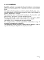
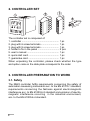
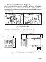
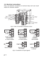
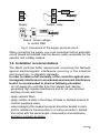
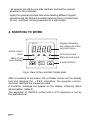
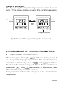
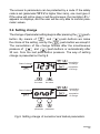
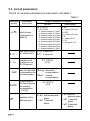
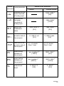
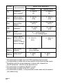
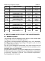
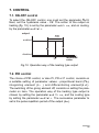
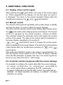
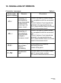
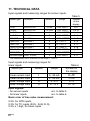
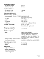
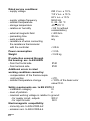
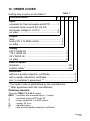
CONTROLLER WITH UNIVERSAL INPUT AND 1 OUTPUT RE22 TYPE USERS MANUAL 1 2 CONTENTS 1. APPLICATION ............................................................................ 5 2. CONTROLLER SET .................................................................. 6 3. CONTROLLER PREPARATION TO WORK ............................. 6 3.1. Safety ................................................................................... 6 3.2. Controller installation in the panel ....................................... 7 3.3. Electrical connection ........................................................... 8 3.4. Installation recommendations ............................................. 9 4. STARTING TO WORK ............................................................. 10 5. PROGRAMMING OF CONTROLLER PARAMETERS ........... 11 5.1. Scheme of the controller menu .......................................... 11 5.2. Setting change ................................................................... 13 5.3. List of parameters .............................................................. 14 6. INPUTS AND OUTPUTS OF THE CONTROLLER ................. 17 6.1. Measuring input ................................................................. 17 6.2. Output ................................................................................ 18 7. CONTROL ................................................................................ 19 7.1. ON -OFF control ................................................................ 19 7.2. PID control ......................................................................... 19 8. ADDITIONAL FUNCTIONS ..................................................... 20 8.1. Display of the control signal .............................................. 20 8.2. Manual control ................................................................... 20 8.3. Controller reaction after sensor damage .......................... 20 8.4. Rate of the set point change ............................................. 21 8.5. Manufacturers settings ..................................................... 21 9. SELECTION OF PID PARAMETER SETTINGS .................... 21 9.1. Auto-tune function ............................................................. 21 9.2. Manual selection of PID parameter settings ..................... 23 10. SIGNALLING OF ERRORS ................................................... 25 11. TECHNICAL DATA ................................................................. 26 12. ORDER CODES ..................................................................... 29 13. MAINTENANCE AND GUARANTEE .................................. 30 3 4 1. APPLICATION The RE22 controller co-operates directly with resistance thermometers (RTD) and thermocouples (TC) or quantity converters into a standard signal. It is destined for temperature control in plastics, food, glass, ceramics, dehydration industries and everywhere when it is necessary to stabilize temperature changes. The measuring input is universal for resistance thermometers and thermocouple sensors or for linear standard signals. The relay output, with a make-brake configuration ( with NOC or NCC contacts) allows to the direct control of low power objects. The manual control and soft-start are also possible. One can protect the controller against the undesirable change of parameters by means of a password. The auto-tuning function permits to select the PID setting in order to a quick output signal adaptation to object parameters. 5 2. CONTROLLER SET 1 RE22 1234 OUT SP MAN AT The controller set is composed of: 1. controller ........................................................ 1 pc 2. plug with 6 screw terminals ........................... 1 pc 3. plug with 8 screw terminals ........................... 1 pc 4. holder to fix in the panel ................................ 2 pcs 5. users manual ................................................ 1 pc 6. quick start card .............................................. 1 pc 7. guarantee card .............................................. 1 pc When unpacking the controller, please check whether the type and option code on the data plate correspond to the order. 3. CONTROLLER PREPARATION TO WORK 3.1. Safety The RE22 controller fulfils requirements concerning the safety of automation measuring instruments acc. to the EN 61010-1 standard, requirements concerning the fastness against electromagnetic interference acc. to EN 61000-6-2 standard and emission of electromagnetic interference occurring in the industrial environment, acc. to the EN 61000-6-4 standard. 6 3.2. Controller installation in the panel Fix the controller in the panel by means of two screw holders acc. to the fig.1. The hole in the panel should have 45+0.6 x 45+0.6 mm dimensions. The material thickness what the panel is made of cannot exceed 15 mm. Fig.1. Controller fixing. Controller overall dimensions are presented on the fig. 2. max. 93 70 48 8 48 RE22 OUT SP MAN AT max.15 Fig.2. View of controller connection strips. 7 3.3. Electrical connections Carry out electrical connections to terminal strips and next, insert strips into controller sockets. Input signals Output Supply Fig.3. View of controller connection strips. Pt100 JUMPER 8 7 6 Pt100 resistance thermometer in 2-wire system Thermocouple Pt1000 JUMPER Pt100 resistance thermometer in 3-wire system Current input 0/4..20mA Fig.4. Connection of input signals. 8 8 7 6 Pt1000 resistance thermometer Voltage input 0..5/10V 9 10 11 Supply Output - relay SSR Supply 10 - 11 + + Load Load Supply Output - binary voltage to control SSR Fig.5. Connection of the supply and load circuit. When connecting the supply, one must remember that an automatic cut-off should be installed near the device, easily accessible for the operator and suitably marked. 3.4. Installation recommendations The RE22 controller fulfils requirements concerning the fastness against electromagnetic interference occurring in the industrial environment acc. to obligatory standards. In order to obtain a full immunity of the controller against electromagnetic interference in an unknown environment interference level it is recommended to observe following principles: - do not supply the controller from the network near devices generating high impulse interference and do not use common earthing circuits with them, - apply network filters, - apply metallic shields in the shape of tubes or braided screens to conduct supplying wires, - wires supplying the measuring signal should be twisted in pairs, and for resistance thermometers in a 3-wire connection, twisted from wires with the same length, cross-section and resistance, and led in a shield as above, 9 - all screens should be one side earthed, and led the nearest possible to the controller, - apply the general principle that wires leading different signals should be led the farthest possible between them (not less than 30 cm), and their crossing executed at a right angle. 4. STARTING TO WORK Display indicating the measured value, set point menu RE22 Active output mark Mark of set point display OUT SP MAN AT Auto-tune mark Manual work mark 3 push-buttons Fig.6. View of the controller frontal plate. After connecting to the power, the controller carries out the display test and displays the r e 2 2 inscription, the program version, and next, displays the measured value. A character message can appear on the display, informing about abnormalities. (table 4). The algorithm of ON-OFF control with a 2oC hysteresis is set by the manufacturer. 10 Change of the set point The way to change the set point during the normal work is shown on the fig. 7. The change limitation is set by SPL and SPH parameters. RE22 RE22 Measured value Set point or OUT SP MAN AT OUT SP MAN AT Change of set point Fig.7. Change of the set point during the normal work.. 5. PROGRAMMING OF CONTROL PARAMETERS 5.1. Scheme of the controller menu After pressing and holding the push-button during at least 2 sec., it is possible to program parameters. The transition between parameters is carried out by means of and push-buttons. The return to the normal working mode follows after the simultaneous pressure of and push-buttons, or automatically, after 30 sec from the last push-button pressure. Some parameters can be invisible - it depends on the current controller configuration. 11 Mode of set point change Mode of normal work Start of changes OUT h___ OUT SP MAN SP MAN SP AT MAN Cancellation of changes Manual work Decrease of value 2sec 2sec code T OUT SP MAN AT T correct code? Fig.8. Menu of controller servicing 12 N err 3sec + Previous parameter Increase of value N auto-tuning start Next parameter AT MAN SP OUT + active access code AT Set point Acceptation of change 2sec AT tune OUT or Measured value Monitoring of control signal inpt t-li r-li C,C C,/t dp iNlo iNHi shif sPrr ramp spl spH pb ti td to Hy out fail aTfn seCU OUT SP MAN AT Mode of parameter change Start of changes Acceptation of changes Cancellation of changes 1-dp OUT SP MAN AT + Decrease of value or previous accounted parameter Increase of value or next accounted parameter The access to parameters can be protected by a code. If the safety code is set (parameter seCU is higher than zero), one must give it. If the value will not be given or will be erroneous, the inscription err appears on displays, and the user will be only able to monitor parameter values. 5.2. Setting change The change of parameter setting begins after pressing the pushbutton. By means of and push-buttons we make the choice of the setting, and by the push-button we accept it. The cancellation of the change follows after the simultaneous and lpush-buttons or automatically after pressure of 30 sec. from the last push-button pressure. The way of setting change is presented on the fig.9. + Start of change 1234 decrease the value acceptation of change increase the value + Start of change oNof previous parameter cancellation of change cancellation of change acceptation of change next parameter Fig.9. Setting change of numerical and textual parameters. 13 5.3. List of parameters The list of controller parameters is presented in the table 1. Table 1 parameter symbol inpt t-lj r-li C,C C,/t dp 14 parameter description kind of input (description in table 2) range of parameter changes sensor [pt1]: Pt100 pt10: Pt1000 t-,: thermocouple of J type t-t: thermocouple of T type t-k: thermocouple of K type t-s: thermocouple of S type t-r: thermocouple of R type t-b: thermocouple of B type t-e: thermocouple of E type t-n: thermocouple of N type t-l: thermocouple of L type linear signal 0-20: lin. current 0-20 mA [4-20]: lin. current 4-20 mA 0-5: lin. voltage 0-5 V 0-10: lin. voltage 0-10 V line type (2-wire [2-p]: 2-wire line or 3-wire line) 1) 3-p: 3-wire line resistance of 2-wire line, for Pt100 sensor 0.0...20.0 W [0.0] way of cold ends [auto]: automatic compensation for compensation thermocouples 2) Hand: manual compensation temperature of cold ends during the manual compensation [°C x10]2) position of the decimal point 0.0...50.0°C [0.0] 0_dp: without decimal place 1_dp: 1 decimal place 0_dp: without decimal place 1_dp: 1 decimal place 2_dp: 2 decimal place symbol parametru iNlo inHi zakres zmian parametru opis parametru czujniki sygna³y liniowe indication for the lower threshold of analog input -1999...9999 3) [0.0] indication for the upper threshold of analog input -1999...9999 3) [100.0] shjf shift of the measurend value -99.9...99.9 °C [0.0] sPrr accretion rate of the set point 0...999.9 / unit [0.0] ramp time unit for the accretion rate of the set point [min]: minute Hour: hour spl lower setting limitation of the set point acc. to table 2 3) [-199.0] spH upper setting limitation of the set point pb proportional band acc. to table 2 3) [850.0] 0...999.9 °C [0.0] -999...999 3) [0.0] 0...999.9 / jedn. [0.0] [min]: minute Hour: hour INLO...INHI 3) [0.0] INLO...INHI 3) [100.0] 0...9999 3) [0.0] 15 symbol parametru ti opis parametru zakres zmian parametru czujniki sygna³y liniowe integration time-constant4) 0...9999 s [0] 0...9999 s [0] td differentiation time-constant 4) 0...999.9 s [0.0] 0...999.9 s [0.0] to pulse repetition period of the output 4) 0.5...99.9 s [20.0] 0.5...99.9 s [20.0] Hy histeresis 5) 0.2...99,9 [2.0] 0.2...999 3) [2.0] out output configuration fail control signal of the output for proportional control in case of sensor damage4) aTfn auto-tuning function seCU safety code 6) dir: cooling signal [inu]: heating signal 0...100.0 % [0.0] 0...100.0 % [0.0] off: locked [on]: unlocked 0...9999 [0] 0...9999 [0] The parameter is visible only for Pt100 resistance thermometer. The parameter is visible only for the execution with thermocouple inputs. 3) Resolution what the given parameter is shown with, depends on the dp parameter - position of the decimal point. 4) The parameter is invisible at ON-OFF control. 5) The parameter is visible at ON-OFF control 6) The parameter is hidden in the parameter review mode only for readout. (for readout only) 1) 2) 16 Measuring ranges for inputs Symbol Input / sensor Resistance thermometer Pt100 pt1 pt10 Resistance thermometer Pt1000 t-, Thermocouple J type Thermocouple T type t-t t-k Thermocouple K type t-s Thermocouple S type Thermocouple R type t-r t-b Thermocouple B type t-e Thermocouple E type Thermocouple N type t-n t-l Thermocouple L type 0-20 Linear current 0-20 mA 4-20 Linear current 4-20 mA 0-5 Linear voltage 0-5 V 0-10 Linear voltage 0-10 V Table 2 Minimum -199°C -199°C -100°C -100°C -100°C 0°C 0°C 0°C -100°C -100°C -100°C -1999 -1999 -1999 -1999 Maximum 850°C 850°C 1200°C 400°C 1372°C 1767°C 1767°C 1820°C 999°C 1300°C 800°C 9999 9999 9999 9999 6. INPUTS AND OUTPUTS OF THE CONTROLLER 6.1. Measuring input The controller has one measuring input, which on can connect different types of sensors or standard signals to. The choice of the input signal is performed by the inpt parameter. For different types of inputs, depending on the option code, one must give additional parameters. For the Pt100 resistance thermometer, one must choose the kind of connection. In a three-wire connection, the line resistance compensation goes on automatically. In a two-wire connection, one can give additionally the line resistance, for thermocouples, one must give the way of temperature compensation of cold ends - automatic or manual, and at manual compensation the temperature of cold ends. 17 For linear inputs, one must give indications for the lower and upper threshold of the analog input. The position of the decimal point is an additional parameter, the parameter dp. For temperature sensors, it defines whether the measured temperature and the set point temperature is to be shown with a place after the decimal point. For linear inputs, it defines the resolution which the measured value and values of some parameters are shown with. The correction of measured value indications is carried out by the shif parameter. 6.2. Output The controller has one measuring input with a switch over contact. It is possible to select the ON-OFF control or proportional (PID) control at the output. For the proportional control, one must additionally set the pulse repetition period. The pulse repetition period is the time which expires between successive switches of the output during the proportional control. The length of the pulse repetition period must be chosen depending on dynamic properties of the object and suitably to the output device for quick-acting processes, it is recommended to apply SSR relays. The relay output is used to control contactors in slow-acting processes. The use of a high pulse repetition period to control quick-acting processes can give unwanted effects in the shape of oscillations. Theoretically, smaller the pulse repetition period better the control is, but for the relay output it should be as high as possible in order to extend the relay life. Recommendations concerning the pulse repetition period. Table 3 Output Pulse repetition period is Load electromagnetic relay recommended >20 s min. 10 s 2 A/230 V a.c. or contactor transistor output 18 min. 5 s 1 A/230 V a.c. 1...3 s Semi-conductor relay (SSR) 7. CONTROL 7.1. ON-OFF control To select the ON-OFF control, one must set the parameter pb=0. Next, set the hysteresis value - Hy. The action of the output on heating (fig. 10.) is set by the parameter out=inu, and on cooling, by the parameter out=dir. output Hy enabled disabled sp measured value Fig.10. Operation way of the heating type output 7.2. PID control The choice of PID control, or also PI, PD or P control, consists on a suitable setting of parameter values - proportional band (pb), integrating element (t i ) and differentiating element(t d ). The switching of the giving element off, consists on setting the parameter on zero. The operation way of the heating type output is chosen by setting the parameter out1=inu, and the cooling type by setting the parameter out=dir. The successive parameter to set is the pulse repetition period of the output (to). 19 8. ADDITIONAL FUNCTIONS 8.1. Display of the control signal After pressing the push-button, the value of the control signal (0...100%) appears on the display. On the first digit, the mark h is displayed. The return to the normal operation follows after the simultaneous pressure of and push-buttons. 8.2. Manual control The manual control gives the possibility, among other things, to identify and test the object or control it after the sensor damage. The entry into the manual control mode follows after holding down the push-button when displaying the control signal. The manual control is signaled by the diode pulsation, marked as MAN. The controller breaks the automatic control and begins the manual control of the output. The value of the control signal is displayed on the lower display, preceded by the symbol h. and push-buttons serve to change the control signal, which is displayed on the lower display. The exit to the normal working mode follows after the simultaneous pressure of and push-buttons. After setting the ON-OFF control on the output 1 (parameter PB = 0), one can set the control signal on 0% or 100% of power, however when the PB parameter is greater than zero, the control signal can be set on any value from the 0...100% range. 8.3. Controller reaction (response) after the sensor damage It is possible to configure the output state after the sensor damage. - at output configuration for proportional control(PB>0) the control signal value is defined by the failparameter, - at output configuration for the ON-OFF control, the output will be disabled - at output operation as heating, or enabled - at output operation as cooling. 20 8.4. Rate of the set point change - soft-start The limitation of the temperature accretion rate is performed through the gradually change of the set point. This function is activated after switching the controller supply on and during the change of the set point. This function allows to reach in a gentle way the achievement from the current temperature to the set point. One should write the accretion value to the sprr parameter and the time unit to the ramp parameter. An accretion value equal to zero means, that the soft-start is disabled. 8.5. Manufacturers settings One can restore manufacturers settings during the supply switching and push-buttons till the moment on by holding down when the inscription fabr appears on the upper display. 9. SELECTION OF PID PARAMETER SETTINGS 9.1. Auto-tuning The controller has the function of the automatic PID setting choice. These settings ensure the optimal control in the majority of cases. To start the auto-tuning, one must transit to the tune parameter (acc. to the fig.8) and hold down the push-button during at least 2 sec. If the proportional band is equal zero or the atfn parameter is set on off , there will not be possible to start the auto-tuning. The flickering upper display informs about the activity of the autotuning function. The duration of the auto-tuning function depends on object dynamic properties and can last maximally 10 hours. During the auto-tuning, or directly after, overshoots can occur and therefore, one must set a smaller set point, if it is possible. 21 The auto-tuning is composed of following stages: - switching the control signal off, and stabilization of the object temperature (from 2 minutes till 3 hours), - switching the control signal (100%) on, and determination of the object characteristic (maximally 10 hours), - calculation of PID settings and their storage in the non-volatile memory, - switching the PID control on with new settings. The auto-tuning process may not start or be interrupted without the PID control if: - the set point is too near to the measured value, i.e. the control deviation is smaller than 6.25% of the range, - the time of the preliminary object stabilization or the admissible auto-tuning duration time will be overrun, - a controller supply decay will occur, - the push-button has been pressed, - calculated parameter values are beyond the range. In such cases, the control with previous users settings will start. 22 9.2. Manual selection of PID parameter settings Method of response to a unitary jump Y[%] 100 0 t [s] measured value ∆PV ∆t t [s] T0 Fig.11. Selection of settings by the method of response to a unitary jump. One must read out the delay time To and the maximal temperature accretion rate from the object characteristic presenting the controlled value in the function of time, from the dependence: DPVmax Vmax = Dt Calculate PID settings acc. to following formulas: Pb=1.1.Vmax.T0 - proportional band ti=2.4.T0 td=0.4.T0 - integration time constant - differentiation time constant Oscillation method around the set point Set the ON-OFF control with a minimal hysteresis. Set the set point on a normal work level (or on a lower one, if overshoots would cause damages) and normal load conditions. 23 Measured value P T t[s] 100% Y[%] t[s] Fig.12. Selection of settings by the oscillation method. Calculate controller settings acc. to given formulas: Pb = P ti = T td = 0.25 * T Correction of PID settings Since PID parameters interact between them, one must introduce changes only of one parameter. The best is to choose parameters changing the value into a twice greater or twice smaller one. During changes, one should be guided by following principles: a) Slow jump answer: - decrease the proportional band, - decrease the integration and differentiation time. b) Over-regulations: - increase the proportional band, - increase the differentiation time. c) Oscillations: - increase the proportional band, - increase the integration time, - decrease the differentiation time. d) Instability: - increase the integration time. 24 10. SIGNALLING OF ERRORS Character messages Error code (upper display) Table 4 Reason Procedure Exceeding of the measuring range downwards or short-circuit occurring in the sensor circuit Check if the type of chosen sensor is in compliance with the connected one. Check if values of input signals are situated in the appropriate range. If so, check whether there is no shortcircuit in the sensor circuit. Herr Exceeding of the measuring range upwards or break in the sensor circuit Check if the type of chosen sensor is in compliance with the connected one. Check if values of input signals are situated in the appropriate range. If so, check whether there is no shortcircuit in the sensor circuit. ater The auto-tuning has not been finished successfully Check reasons of breaking the tuning process in auto-tuning point Discalibrated input Connect again the controller supply and if it cannot help, contact the nearest authorized service shop. lerr erad 25 11. TECHNICAL DATA Input signals and measuring ranges for sensor inputs. Sensor type Standard Notation Pt100 Pt1000 Fe-CuNi Cu-CuNi NiCr-NiAl PtRh10-Pt PtRh13-Pt PtRh30-PtRh6 NiCr-CuNi NiCrSi-NiSi chromel-kopel EN 60751+A2 Pt100 Pt1000 J T K S R B E N L EN 60751+A2 EN 60584-1 EN 60584-1 EN 60584-1 EN 60584-1 EN 60584-1 EN 60584-1 EN 60584-1 EN 60584-1 GOST R 8.585 Table 5 Range Symbol on the display -199...850°C -199...850°C -100...1200°C -100...400°C -100...1372°C 0...1767°C 0...1767°C 0...1820°C* -100...999°C -100...1300°C -100...800°C pt1 pt10 t-, t-t t-k t-s t-r t-b t-e t-n t-l * The measurement error is defined for the range 0...1820°C Input signals and measuring ranges for linear inputs Sensor type Linear current input Linear current input Linear voltage input Linear voltage input Table 6 Notation Range Symbol on the display I I U U 0...20 mA 4...20 mA 0...5 V 0...10 V 0-20 4-20 0-5 0-10 Input signals: - for sensor inputs - for linear inputs acc. to table 5 acc. to table 6 Basic error of true value measurement: 0.2%, for RTD inputs, 0.3%, for TC inputs (0.5% - for B, R, S), 0.2% ± 1 digit, for linear inputs 26 Measurement time: - for sensor inputs - for linear inputs 0.33 s 0.16 s Input resistance: - for voltage input - for current input 150 kW 4W Detection of error in the measuring circuit: - thermocouple, Pt100, PT1000 overrunning of the measuring range - 0...10 V over 11 V - 0...5 V over 5,25 V - 0...20 mA over 22 mA - 4...20 mA under 1 mA and over 22 mA Control algorithm: Range of controller parameter settings: P, PD, PI, PID, too-state with hysteresis see table 1 Kind of outputs: - relay switch over contact maximal load-carrying capacity: voltage: 250 V a.c., 150 V d.c. current: 5 A 250 V a.c., 5 A 30 V d.c. resistance load: 1250 VA, 150 W - binary voltage (without isolation voltage 5 V from the sensor side) resistance limiting the current 66 W; Way of output action: - reverse - direct for heating for cooling Signalling: - output switching on - display of set point - manual control mode - auto-tuning mode 27 Rated service conditions: - supply voltage - supply voltage frequency ambient temperature storage temperature relative air humidity - external magnetic field - preheating time - work position - resistance of wires connecting the resistance thermometer with the controller 230 V a.c. ± 10 % 110 V a.c. ± 10 % 24 V a.c. ± 10 % 50/60 Hz 0...23...50 °C -20...+70 °C < 85 % (without condensation) < 400 A/m 30 min any < 20 W Power consumption < 3 VA Weight < 0.25 kg IP protection ensured through the housing: acc. to EN 60529 - from the frontal side - from terminal side Additional errors in rated working conditions caused by: - compensation of the thermocouple cold junction - ambient temperature change IP40 IP20 £ 2oC, £ 100% of the basic error value/10 K. Safety requirements acc. to EN 61010-1 - installation category III - level of pollution 2 - maximal working voltage in relation to ground: - for supply circuit, outputs 300 V - for input circuits 50 V Electromagnetic compatibility: - immunity acc. to EN 61000-6-2 - emission acc. to EN 61000-6-4 28 12. ORDER CODES Table 7 Coding way is given on the table 7. Controller RE22 - X X X XX X Input universal for thermocouples and RTD .......... 1 universal linear current 0/4..20 mA, and linear voltage 0...5/10 V ......................... 2 on order ......................................................... X Output relay ..................................................................... 1 binary 0/5 V to SSR control ................................ 2 on order ............................................................... X Supply 230 V 50/60 Hz .......................................................... 1 110 V 50/60 Hz ........................................................... 2 24 V 50/60 Hz ............................................................ 3 on order ...................................................................... X Kind of option standard .......................................................................... 00 custom-made* ............................................................... XX Additional without a quality inspection certificate .................................... 8 with a quality inspection certificate ......................................... 7 acc. to customers agreement ** ............................................ X * The option code is established by the manufacturer. ** After agreement with the manufacturer. Ordering example: The code: RE22-1-2-3-00-7 means: RE22 - controller with universal input + 1 output 1 - universal input for RTD and TE 2 - binary output 0/5 V to SSR control 3 - supply: 24 V a.c. 00 - standard option 7 - with an extra quality inspection certificate 29 13. MAINTENANCE AND GUARANTEE The RE22 controller does not require any periodical maintenance. In case of some incorrect operations: 1. After the dispatch date and in the period stated in the guarantee card One should return the instrument to the Manufacturer Quality Inspection Dept. If the instrument has been used in compliance with the instructions, the Manufacturer warrants to repair it free of charge. The disassembling of the housing causes the cancellation of the granted guarantee. 2. After the guarantee period: One should turn over the instrument to repair it in a certified service workshop. Spare parts are available for the period of five years from the date of purchase. Our policy is one of continuous improvement and we reserve the right to make changes in design and specifications of any products as engineering advances or necessity requires and revise the above specifications without notice. 30 31 © LUMEL S.A., RE22-KZ1340/February 2007 Lubuskie Zak³ady Aparatów Elektrycznych - LUMEL S.A. ul. Sulechowska 1, 65-022 Zielona Góra, Poland Tel.: (48-68) 32 95 100 (exchange) Fax: (48-68) 32 95 101 www.lumel.com.pl e-mail:[email protected] Export Department: Tel.: (48-68) 329 53 02 or 53 04 Fax: (48-68) 325 40 91 e-mail: [email protected] 32