1
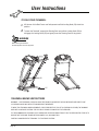
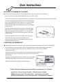
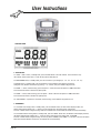
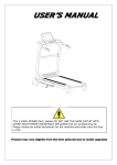
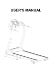
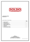
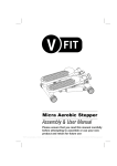
SERIAL NO. HY1967-UK
TRV1-12 Folding Power Treadmill
Assembly & User Manual
Please ensure that you read this manual
carefully before attempting to assemble or
use your new product and retain for future use
Contents
Section
Page
General Information . . . . . .
3
Before you start . . . . . . . . . .
4
Safety . . . . . . . . . . . . . . . . . . . . . 5
Exercise Information . . . . . .
7
Assembly . . . . . . . . . . . . . . . . . 10
User Instructions . . . . . . . . . . 15
Protect the environment by not disposing of this product with household waste.
General Information
Quality
Guarantee
This exercise product has been designed and
manufactured to comply with the latest (BS EN 957)
British and European Safety Standards.
This product is guaranteed for DOMESTIC USE ONLY for
a period of 1 YEAR from the original certified date of
purchase. During this period we have the right to: -
Questions
a). Provide parts for the purchaser to effect repair.
b). Repair the product, returned to our warehouse
(at the purchaser's cost).
c). Replace the product if it is deemed (by us) to be
economical to do so.
Should you encounter any difficulty with the assembly,
operation or use of your exercise product or if you
think that you may have parts missing, please DO NOT
return it to your retailer but contact us first for help and
advice, asking for CUSTOMER SUPPORT, by any of the
following means.
This guarantee does not cover wear and tear on
upholstery or consumables.
Tel:- 01535 637711 or
Fax:- 01535 637722 or
Email:- [email protected]
This guarantee does not cover abuse, defects caused by
storage or use outside those intended.
CUSTOMER SUPPORT is open from 9.00am to 5.00pm
from Monday to Friday
If you need to advise us of a defect with your product and
in order for us to service any requirement for replacement
parts or repairs, we will ask for proof of purchase. Failure
to do so will result in any claim for replacement parts or
repairs being refused.
Beny Sports Co. UK Ltd.
Unit 8, Riparian Way,
The Crossings, Cross Hills,
West Yorkshire.
BD20 7BW
This guarantee, (both given and implied) applies to the
original purchaser only, is not transferable and will be
invalidated if used outside of the above criteria.
Queries
This guarantee is valid only in the United Kingdom and Eire.
If you do have any queries, please ensure that you have
the following information ready for our Customer Support
Staff:
This does not affect your statutory rights as a consumer.
YOUR NAME
YOUR ADDRESS
YOUR PHONE NUMBER
PRODUCT MAKE OR BRAND
PRODUCT MODEL
PRODUCT SERIAL NUMBER
DATE OF PURCHASE
NAME OF RETAILER
PART NUMBERS REQUIRED
Customer Support
Tel:- 01535 637711 or
Fax:- 01535 637722 or
Email:- [email protected]
CUSTOMER SUPPORT is open from 9.00am to
5.00pm from Monday to Friday
Beny Sports Co. UK Ltd.
Unit 8, Riparian Way,
The Crossings, Cross Hills,
West Yorkshire
BD20 7BW
Page 3
Before you Start
Tools
If required, most of our products products are supplied with basic tools,
which will enable youto successfully assemble your product. However,
you may find it beneficial to have a soft-headed hammer and perhaps an
adjustable spanner handy as this may help.
Prepare the Work Area
It is important that you assemble your product in a clean, clear,
uncluttered area. This will enable you to move around the product
while you are fitting components and will reduce the possibility of
injury during assembly.
Work with a Friend
You may find it quicker, safer and easier to assemble this product with
the help of a friend as some of the components may be large, heavy
or awkward to handle alone.
Open the Carton.
Carefully open the carton that contains your product, taking note of
the warnings printed on the carton to ensure that the risk of injury is
reduced. Be aware of sharp staples that may be used to fasten the
flaps as these may cause injury. Be sure to open the carton the right
way up, as this will be the easiest and safest way to remove all the
components.
Unpack the Components
Carefully unpack each component, checking against the parts list that
you have all the necessary parts to complete the assembly of your
product.
Please note that some of the parts may be pre-fitted to major
components, so please check carefully before contacting our
CUSTOMER SUPPORT team.
In any event, please do not return the product to your retailer before
contacting us first.
Page 4
Safety
Before you undertake any programme of exercise that will increase
cardiovascular activity please be sure to consult with your doctor.
Frequent strenuous exercise should be approved by your doctor and
proper use of your product is essential. Please read this manual
carefully before commencing assembly of your product or starting to
exercise.
*Please keep all children away from exercise products when in
use. Do not allow children to climb or play on them when they
are not in use.
*For your own safety, always ensure that there is at least 1 Metre
of free space in all directions around your product while you are
exercising.
*Regularly check to see that all nuts, bolts and fittings are
securely tightened. Periodically checking all moving parts for
obvious signs of wear or damage.
*Clean only with a damp cloth, do not use solvent cleaners. If you
are in any doubt, do not use your product, but contact
CUSTOMER SUPPORT by any of the means listed on the
opposite page.
*Before use, always ensure that your product is positioned
on a solid, flat surface. If necessary, use a rubber mat
underneath to reduce the possibility of slipping in use.
Warning
If any part of your product
becomes damaged, broken
or badly worn do not use
the equipment until the
defective parts have been
replaced
*Always wear appropriate clothing and footwear such as training
shoes when exercising. Do not wear loose clothing that could
become caught or trapped during exercise.
Storage and Use
Your product is intended for use in clean dry conditions. You
should avoid storage in excessively cold or damp places as this may
lead to corrosion and other related problems that are outside our
control.
Weight Limit
Your product is suitable for users weighing:
220 LBS / 15.6 Stones / 100 KG or less.
Conformity
This product conforms to:
(BS EN 957) - PARTS 1 and 6 Class (H) - HOME USE - Class (C).
It is NOT suitable for therapeutic purposes.
Page 5
Safety
Safety-Treadmill Specific
When using an electrical appliance, basic precautions should always be followed,
including the following:
Read all instructions before using the treadmill.
DANGER – To reduce the risk of electric shock:
Always unplug this appliance from the electrical outlet immediately after using
and before cleaning.
WARNING – To reduce the risk of burns, fire, electric shock, or injury to persons:
1.
An appliance should never be left unattended when plugged in. Unplug from the
power outlet when not in use, and before putting on or taking off parts.
2. Close supervision is necessary when this appliance is used by, on, or near children,
invalids, or disabled persons.
3. Use this appliance only for its intended use as described in this manual. Do not use
attachments not recommended by the manufacturer.
4.
Never operate this appliance if it has a damaged cord or plug, if it is not working
properly, if it has been dropped or damaged, or dropped into water.
Contact D. I. Support
.
5.
Do not carry this appliance by power supply cord or use cord as a handle.
6.
Keep the cord away from heated surfaces.
7.
Never operate the appliance with the air openings blocked. Keep the air openings
free of lint, hair, and the like.
8.
Never drop or insert any object into any opening.
9.
Do not use outdoors.
10. Do not operate where aerosol (spray) products are being used or where
oxygen is being administered.
11. To disconnect, turn all controls to the off position, then remove the plug from the power outlet.
12. Connect this appliance to a properly earthed power outlet only.
13. The appliance is intended for household use only.
14. This product is suitable for users weighing 220 LBS / 15.6 Stones / 100 KG or less.
SAVE THESE INSTRUCTIONS
Page 6
Exercising Information
Warm Up
Beginning
How you begin to exercise will vary
from person to person. If you have
not exercised for a long period of time,
have been inactive for a while, or are
severely over weight you MUST start slowly,
increasing your exercise time gradually,
by perhaps only a few minutes for each
session per week.
Combine a carefully structured nutritious
diet with a simple but effective exercise
routine and this can help make you feel
better, look better and will almost certainly
enable you to enjoy life more.
Aerobic Fitness
Aerobic exercise is simply defined as
any sustained activity that increases
the supply of oxygen to your muscles
via the blood pumped by your heart.
With regular exercise, your cardiovascular
system will become stronger and more
efficient. Your recovery rate i.e. the time
taken for your heart to reach its normal
resting level, will also decrease.
Initially you may only be able to exercise
for a few minutes each day. Do not
hesitate to breathe through your mouth
should you need more oxygen. Use the
"talk test". If you cannot carry on a
conversation while exercising, you are
working too hard! However, aerobic fitness
will be gradually built up with regular
exercise, over the next six to eight weeks.
Do not be discouraged if it takes longer
than this to begin to feel less lethargic,
everyone is different and some will achieve
their targets quicker than others.
Work at your own, comfor table pace and
the results will come. The better your
aerobic fitness the harder you will
have to work to stay in your target zone.
A successful exercise programme consists
of three parts, Warm Up, Aerobic Exercise
and Cool Down. Never start a training
session without warming up. Never finish
one without cooling down correctly.
Perform between five and ten minutes of
stretching before starting your workout to
prevent muscle strains, pulls and cramps.
Aerobic Exercise Session
Those new to exercise should exercise no
more than every other day to start with.
As your fitness level increases, increase
this to 2 in every 3 days.
When you are comfortable with your
routine, exercise for 6 days per week.
Always take at least one day off per week.
Exercising in your Target
Zone
To ensure that your heart is working in its
exercise target zone, you need to be able
to take your pulse. If you do not have a
pulse monitor (either from the product
you are using or a proprietary independent
unit) you will need to locate the pulse in
your carotid artery. This is situated in the
side of the neck and can be felt by using
the index and middle fingers. Simply
count the number of beats you feel in 10
seconds and then multiply by six to get
your pulse rate. This should be taken
before you start to exercise for easy
reference.
People who have a greater aerobic
fitness, have a lower resting pulse level
and will also be able to exercise with a
higher pulse level.
Target Zone
To determine your target zone, see the
chart opposite. If you are new to exercise
and by definition unfit, refer to the left
column. If you exercise regularly and have
good aerobic fitness, refer to the right
column.
Page 7
Exercising Information
Target Zone (con't)
USERS
AGE
UNCONDITIONED
TARGET ZONE - A
CONDITIONED
TARGET ZONE - B
(Years)
20-24
25-29
30-34
35-39
40-44
45-49
50-54
55-59
60 and over
(Beats per Minute)
145 - 165
140 - 160
135 - 155
130 - 150
125 - 145
120 - 140
115 - 135
110 - 130
105 - 125
(Beats per Minute)
155 - 175
150 - 170
145 - 165
140 - 160
135 - 155
130 - 150
125 - 145
120 - 140
115 - 135
Note
Incorrect or excessive
training may damage your
health. Please read the
exercise information first.
Cool Down
To decrease fatigue and muscle soreness, you should also cool down
by walking at a slow relaxed pace for a minute or so, to allow your
heart rate to return to normal.
Warm Up and Cool Down Exercises
Hold each stretch for a minimum of ten seconds and then relax.
Repeat each stretch two or three times. Do this before your Aerobic
Exercise session and also after you have finished.
Head Roll
Rotate your head to the right for one count, feeling a slight pull on the
left side of your neck. Next, rotate your head back for one count,
stretching your chin. Then rotate your head to the left for one count,
feeling a slight pull on the right side of your neck. Lastly, drop your
head to your chest for one count. Repeat 2 to 3 times.
Toe Touch
Slowly bend forward from your waist, letting your back and shoulders
relax as you lower your trunk. Gently stretch down as far as is
comfortable and hold for 10 seconds.
Page 8
Exercising Information
Shoulder Lift
Rotate and lift your right shoulder up towards your ear for one count.
Relax then repeat for the left shoulder.
Repeat 3 - 4 times.
Calf / Achilles Stretch
Turn towards the wall and place both hands on it. Support yourself
with one leg while the other is placed behind you with the sole flat on
the floor. Bend the front leg and lean towards the wall, keeping the
rear leg straight so that the calf and Achilles tendon are stretched
hold for 5 seconds. Repeat with the other leg.
Repeat 2 - 3 times.
Side Stretch
Open both arms to the side and gently lift them above your head.
Reach your right arm as high as you can for one count, gently
stretching the muscles of the stomach and lower back. Repeat the
action with your left arm.
Repeat 3 - 4 times.
Inner Thigh Stretch
Sit on the floor and pull your legs toward your groin, the soles of your
feet together. Hold your back straight and lean forward over your feet.
Tighten the thigh muscles and hold for 5 seconds. Release and repeat
3 - 4 times.
Hamstring Stretch
Sit on the floor with your right leg extended and place your left foot
flat against the right inner thigh. Stretch forward toward the right foot
and hold for 10 seconds. Relax and then repeat with the left leg
extended.
Repeat 2 - 3 times.
Page 9
Assembly
Overview Drawing
USING THE SAFETY KEY
You will need to install the SAFETY KEY (2) in order to operate your product.
This acts as an emergency STOP should you encounter any difficulties.
SETTING UP THE SAFETY KEY
Note
The free space required around
your product
With the product switched off, place the Safety Key (2) into the recess in the
front of the Computer Console (1). Extend the Safety Key chord until you can
stand with both feet on the rear of the Running Belt with your heels on the Rear
Roller, clip the chord to your clothing and take up the slack in the chord until it’s
tight. The idea is if you stumble or fall, the Safety Key will pull out and stop the
treadmill. You can test this by standing in the normal position you would use
the product, take a step backwards and the Safety Key should pull out.
Note
The foot print for this product is
1630mm x 645mm.
The assembled weight is 45kg.
m
0m
163
m
645m
Safe
rea
ty A
Page 10
Assembly
ACCESSORY FITMENT LIST
These are all the accessories you will need to comp lete the assembly of your product.
The following accessories are supplied in a pack and should be checked before attempting assembly.
Item 5
Qty 10
Item 6
Qty 14
Item 7
Qty 2
Item 19
Qty 2
Item 54
Qty 4
Qty 1
Item 66
Qty 1
Item 2
Qty 1
Item 67
Qty 1
Page 11
Assembly
Carefully unpack each component, checking against the parts list that
you have all the necessary parts to complete the assembly of your
product.
Beny Sports Co. UK Ltd
Unit 8, Riparian Way,
The Crossings, Cross Hills,
West Yorkshire.
BD20 7BW
Please note that some of the parts may be pre-fitted to major
components, so please check carefully before contacting our
CUSTOMER SUPPORT team.
In any event, please do not return the product to your retailer before
contacting us first.
Tel:- 01535 637711 or
Fax:- 01535 637722 or
E-mail:- [email protected]
CUSTOMER SUPPORT is open from 9.00am to 5.00pm from Monday
to Friday
Two persons may be required to finish the assembly steps.
(Caution!! Please follow the assembly steps below to aviod injury.)
1.
Lift up and assemble the Left and Right Upright (4L & R) and secure to the Base Frame (14)
using 2 x M8 x 15mm Allen Bolts (5), 1 x M8 x 50mm Allen Bolt (19) and 2 x M8 Lock Washers
(6) for each side.
Note
Do NOT FULLY TIGHTEN any
Bolts, Nuts or Fittings at this
stage unless specifically
instructed to do so.
Page 1
Assembly
2.
Connect the Upper Control Wire (62) in the Right Upright to the matching wire from the
Console (1). Fit the Console (1) to the Uprights (4L &R) using 3 x M8 x 15mm Allen Bolts
(5) and 3 x M8 Lock Washers (6) on each side.
Page 13
Assembly
3.
Page 14
Assemble the Cross Bar (13) to the inside of the Uprights (4L & R) using 2 x M8 x 45mm
Allen Bolts (7) and 2 x M8 Lock Washers (6).
Assembly
4.
Attach the Upright Covers (20L & R) using 4 x M4 x 15mm Self Tapping Screws (54).
Note
FULLY TIGHTEN all Bolts, Nuts
and Fittings now, ensuring that
your product in located on a
clear flat surface before doing so.
Your product will now be ready
to use.
Page 15
User Instructions
TO FOLD YOUR TREADMILL
1. Lift the rear of the Main Frame and fold upwards until the Locking Knob (29) locks into
position.
2. To lower the Treadmill, support the Running Deck and pull the Locking Knob (29) to
disingage the Locking Knob (29) and gently lower the Running Deck to the ground.
WARNING
When lowering the treadmill.
The Running Deck must be supported.
29
25
TREADMILL MOVING INSTRUCTIONS
WARNING: - THIS TREADMILL IS HEAVY & WHILE THE FRAME IS BALANCED IT SHOULD BE MOVED WITH GREAT CARE
AS POSSIBLE INJURY MAY RESULT FROM INCORRECT MOVEMENT.
TO MOVE THIS TREADMILL WHEN ASSEMBLED, PLEASE ENSURE THAT YOU LIFT (& CONFIRM AS LOCKED) THE RUNNING
DECK INTO AN UPRIGHT POSITION. THE POP-PIN OR FRAME LOCK MUST BE FULLY ENGAGED.
TILT THE RUNNING DECK TOWARDS YOU TO DISENGAGE THE FLOOR FRAME FROM ITS FLAT POSITION ON THE FLOOR & TO
ENSURE THAT THE FRAME TRANSPORTATION WHEELS (25) RUN SMOOTHLY.
CAREFULLY MANOEUVER THE TREADMILL TO ITS DESIRED POSITION.
Page 16
User Instructions
ADJUSTING THE RUNNING BELT TRACKING
If the Running Belt tends to move off central during operation, step off the belt and stop the Treadmill.
Start the Treadmill in Manual Programme Mode and adjust the speed to 3mph.
Take the 5mm Allen Wrench and adjust the Rear Roller Location Bolts, which are accessible through the Rear Frame Caps.
If the belt is moving towards the RIGHT side of the Treadmill Running
Board, turn the RIGHT Rear Roller Location Bolt 1/4 turn CLOCKWISE
and let the Running Belt find its new position. If it is still moving
towards the RIGHT side of the Treadmill Running Board, turn the Bolt
a further 1/4 turn.
If the belt is moving towards the LEFT side of the Treadmill Running
Board, turn the LEFT Rear Roller Location Bolt 1/4 turn CLOCKWISE
and let the Running Belt find its new position. If it is still moving
towards the LEFT side of the Treadmill Running Board, turn the Bolt
a further 1/4 turn.
Continue this operation until the Running Belt is running centrally.
Please take care to ensure that the Running Belt does not
foul the Side Strips, as this will cause premature wear to both the
Running Belt and the Side Strips.
LUBRICATING THE RUNNING BELT
Dependent upon usage and user weight it will be necessary periodically to lubricate the underside of the Running Belt.
To ensure that this is done successfully, take the 5mm Allen Wrench and adjust the Rear Roller Location Bolts,
which are accessible through the Rear Frame Caps. Rotate each bolt a full 4 turns ANTI-CLOCKWISE
to slacken off the belt.
Lift the sides of the belt and run a small bead of lubricant onto the Running Board and if
possible spread this with a small brush or cloth to ensure even coverage on the
Running Board.
Re-tighten the Running Belt by adjusting the Rear Roller Location Bolts
CLOCKWISE until the belt is running centrally on the Running Board.
Please see table below for suggested lubrication frequency.
Please follow the guide below to ensure efficient operation of your Treadmill.
Light Use of up to 3 hours per week – Lubricate every 8 months
Moderate Use of up to 5 hours per week – Lubricate every 4 months
Heavy or Extended Use over 5 hours per week – Lubricate every 3 months
Page 17
User Instructions
1. CONSOLE PANEL
2. FUNCTION KEY:
2.1“START” “STOP”: button, in standby mode, press the START button to start the treadmill. Press the STOP to stop
the treadmill, all data will be saved. To clear all data, pull the Safety Key out.
2.2 PROGRAMME: button, in standby mode, press the "P" button to cycle through (P1、P2、P3、P4、P5、P6、P7).
2.3 MODE: button, in standby mode, press the "M" button to select between Time, Distance and Calories.
Change the Time, Distance and Calories by pressing "+ or -" buttons, then press START to begin exercise.
2.4 SPEED”+”: button, while exercising, press the Speed "+" button to increase the speed in 0.1KM/H increments.
Press and hold the button to increase the speed quicker.
2.5 SPEED”-“: button, while exercising, press the Speed "-" button to decrease the speed in 0.1KM/H increments.
Press and hold the button to decrease the speed quicker.
2.6 “QUICK SPEED”: 4 speed short cut buttons, while exercising, choose between any speed 3,6,9,12.
3. PROGRAMME
3.1 Countdown Time training mode: in standby mode, press the “MODE” button, the Time window display will flash, the
default setting displays 30:00, press +/- button to set the required value. The setting range: 5-99 minutes.
Press the “START” button to begin exercising. When the countdown time reaches 00:00, the treadmill will stop automatically.
3.3 Countdown Distance training mode: in standby mode, press the “MODE” button twice, the Distance window display will flash,
the default setting displays 5.0KM, press +,- button to set the required value. The setting range: 0.5-99.0KM.
Press the “START” button to begin exercising. The start up speed is 0.8KM/H, press SPEED+/- to increase or decrease the speed.
When the countdown Distance reaches 0.0, the treadmill will stop automatically.
Page 18
User Instructions
3.4 Countdown Calorie training mode: in standby mode, press the “MODE” button 3 times, the Calories window display will flash,
the default setting displays 100CAL, press the +,- button to set the required value. The setting range: 20-990CAL.
Press the “START” button to begin exercising. The start up speed is 0.8KM/H, press SPEED+/- to increase or decrease the speed.
When the countdown Calories reach 0, the treadmill will stop automatically.
3.5 Programme mode: Press the Programme "P" button and select between P1-P7. Once selected, the Time Window
will flash. The default setting is 30:00 minutes. Press the +/- button to change the Time between: 5-99 minutes.
Press the “START” button to begin exercising. When the countdown Time reaches 00:00, the treadmill will stop automatically.
You can change the Programme data at any point during the exercise, press the +/- button.
3.6 Programme Table
level
1
2
3
4
5
6
7
8
9
10
11
12
13
14
15
16
17
18
19
20
21
22
23
24
25
26
27
28
29
30
P1
Speed
3.0
4.0
5.0
6.0
7.0
8.0
8.0
8.0
8.0
5.0
5.0
8.0
8.0
8.0
8.0
5.0
5.0
8.0
8.0
8.0
8.0
5.0
5.0
8.0
8.0
8.0
8.0
6.0
5.0
4.0
P2
Speed
5.0
6.0
7.0
8.0
9.0
10.0
10.0
10.0
10.0
7.0
7.0
10.0
10.0
10.0
10.0
7.0
7.0
10.0
10.0
10.0
10.0
7.0
7.0
10.0
10.0
10.0
10.0
6.0
3.0
2.0
P3
Speed
4.0
4.0
4.0
5.0
5.0
5.0
6.0
6.0
6.0
7.0
7.0
7.0
8.0
8.0
8.0
9.0
9.0
9.0
10.0
10.0
10.0
10.0
10.0
10.0
10.0
10.0
7.0
7.0
5.0
3.0
P4
Speed
2.0
3.0.
4.0
5.0
6.0
6.0
6.0
6.0
6.0
5.0
4.0
3.0
3.0
4.0
5.0
6.0
6.0
6.0
7.0
7.0
7.0
6.0
5.0
4.0
3.0
3.0
7.0
7.0
3.0
1.0
P5
Speed
3.0
4.0
5.0
6.0
7.0
7.0
7.0
7.0
7.0
6.0
5.0
4.0
4.0
5.0
6.0
7.0
7.0
7.0
8.0
8.0
8.0
7.0
6.0
5.0
4.0
4.0
5.0
6.0
7.0
6.0
P6
Speed
4.0
5.0
6.0
7.0
8.0
8.0
8.0
8.0
8.0
8.0
7.0
6.0
5.0
5.0
6.0
7.0
8.0
8.0
8.0
9.0
9.0
9.0
8.0
7.0
6.0
5.0
5.0
5.0
4.0
4.0
P7
Speed
4.0
4.0
4.0
4.0
4.0
5.0
5.0
5.0
5.0
5.0
5.0
6.0
6.0
6.0
6.0
6.0
6.0
6.0
7.0
7.0
7.0
7.0
7.0
8.0
8.0
8.0
8.0
7.0
6.0
5.0
Page 19
User Instructions
4. HEART BEAT TEST
4.1 Place both hands on the Pulse Pads, the Speed/Pulse window will show your pulse value.
4.2 Check before exercise, feet standing on the both sides of the side rails, and both hands holding the pulse pads,
wait for 20 seconds and your Heart Rate will be displayed.
4.3 Check after exercise, feet standing on the both sides of the side rails, and both hands hold the pulse pads,
wait for 20 seconds and your Heart Rate will be displayed.
(Note: In order to get a more accurate reading, please do not test while running)
5. ERROR SIGNAL
5.1 Please check the error Signal display in the window
Er 1: Display panel doesn’t receive signal
Er 3: Over voltage
Er 4: Over current
Er 5: Over weight
Er 6: Motor connection
Er 7: Controller doesn’t receive signal
SAFE: Safety protection
Page 20
User Instructions
OPERATION INSTRUCTION
1. BEFORE START
1.1 Plug in the power cord to a suitable earthed outlet and turn the On/Off Switch to the ON position at the front of the machine.
If the machine is not in use, please turn off the power.
1.2 Clip the safe key on to your clothes and place the Safety Key magnet into the computer. If the Safety Key is not placed in the
correct position the treadmill will not work.
2. START
2.1 Press the START button and the treadmill will begin to work with a starting speed 1.0KM/h
2.2 Press the +/- button to increase or decrease the speed in 0.1 KM/h increments. Press and hold the button to increase or
decrease the speed quicker. The highest speed is 12KM/h while the lowest is 1.0 KM/h.
3. TWO WAYS TO STOP THE MACHINE
3.1 Pulling the Safe Key will stop the treadmill quickly. To restart simply place the Safety Key back onto the Computer and press
the Start button to begin your exercise.
3.2 Press STOP button and the treadmill will stop working
IMPORTANT SAFETY INSTRUCTION
1. PREPARATION BEFORE START
1. The treadmill is for home use only.
2. The voltage for the treadmill is 220-250volts AC.
3. Before operating the treadmill, please do a 10-minute warm-up and wear clothes and shoes that are suitable for sports.
4. Do not stand on the treadmill when you adjust, test or start the treadmill.
5. Be careful when you get on or off the treadmill. Before starting the treadmill, please hold the handlebars and place your
feet on the side rails (not the running belt). After starting the treadmill, stand on the belt with the treadmill running at the
lowest speed. Then increase the speed gradually. Before getting off the machine, please decrease the speed to the lowest
level or stop the treadmill to prevent injury.
6. When operating, remove the safety key at any time, the motor will stop working and the computer will give an audiable warning.
7. Children should be supervised by adults when they play on or near the treadmill.
8. The motorised treadmill should be protected from sunshine, damp and dirt. All the parts should be checked and cleaned monthly.
Page 21
Assembly
Page 22
Assembly
PARTS LIST
PART No.
1
2
3
4
5
6
7
8
9
10
11
12
13
14
15
16
17
18
19
20
21
22
23
24
25
26
27
28
29
30
31
32
33
34
35
36
37
38
39
40
41
42
43
44
45
46
47
48
49
50
51
52
53
54
DESCRIPTION
QTY
Computer Console . . . . . . . . . . . . . . . . .1
Safety Key . . . . . . . . . . . . . . . . . . . . . . . 1
Cross Bar . . . . . . . . . . . . . . . . . . . . . . . .1
Upright (L&R) . . . . . . . . . . . . . . . . . . . . 2
M8 x 15mm Allen Bolt . . . . . . . . . . . . . . 12
M8 Lock Washer . . . . . . . . . . . . . . . . . . 14
M8 x 45mm Allen Bolt . . . . . . . . . . . . . . 2
Hand Pulse Pad . . . . . . . . . . . . . . . . . . . 2
Foam Grip . . . . . . . . . . . . . . . . . . . . . . 2
Handlebar . . . . . . . . . . . . . . . . . . . . . . . 2
Round End Cap. . . . . . . . . . . . . . . . . . . 2
Plastic Tube . . . . . . . . . . . . . . . . . . . . . .2
M4.2 x 25mm Self Tapping Screw . . . . . 6
Base Frame . . . . . . . . . . . . . . . . . . . . . . 1
Rubber Foot Pad . . . . . . . . . . . . . . . . . . 2
M10 Nut . . . . . . . . . . . . . . . . . . . . . . . . 2
M10 Flat Washer . . . . . . . . . . . . . . . . . . 2
M10 x 110mm Hex Bolt . . . . . . . . . . . . . 2
M8 x 50mm Allen Bolt . . . . . . . . . . . . . 2
Upright Cover (L & R) . . . . . . . . . . . . . . 2
M8 x 40mm Allen Bolt . . . . . . . . . . . . . . 2
M8.5 Flat Washer . . . . . . . . . . . . . . . . . 14
M8 Nut . . . . . . . . . . . . . . . . . . . . . . . . . 8
Transportation Wheel Tube . . . . . . . . . . 2
Transportation Wheel . . . . . . . . . . . . . . 2
20mm x 20mm End Cap . . . . . . . . . . . . 1
Fold Support Tube Upper . . . . . . . . . . . . 1
Fold Support Tube Lower . . . . . . . . . . . . 1
Locking Knob . . . . . . . . . . . . . . . . . . . . 1
Manual Incline Bar . . . . . . . . . . . . . . . . 1
Rubber Foot Pad . . . . . . . . . . . . . . . . . . 2
Rear Cap (L+R) . . . . . . . . . . . . . . . . . . 2
M4 x 12mm Allen Bolt . . . . . . . . . . . . . . 2
M4.2 x 15mm screw . . . . . . . . . . . . . . . 6
Bumper . . . . . . . . . . . . . . . . . . . . . . . . . 6
Main Frame . . . . . . . . . . . . . . . . . . . . . . 1
M8 x 25mm Hex Bolt . . . . . . . . . . . . . . . 1
Fuse Set . . . . . . . . . . . . . . . . . . . . . . . . 1
Power On/Off Switch. . . . . . . . . . . . . . . 1
M4.2 Spring Washer . . . . . . . . . . . . . . . 4
M5.1 Washer . . . . . . . . . . . . . . . . . . . . .4
M4 x 15mm Screw . . . . . . . . . . . . . . . . 2
Motor Control Board (MCB). . . . . . . . . . .1
M8 x 20mm Hex Bolt . . . . . . . . . . . . . . 4
M8.1 Flat Washer . . . . . . . . . . . . . . . . . 6
Motor . . . . . . . . . . . . . . . . . . . . . . . . . . .1
Drive Belt . . . . . . . . . . . . . . . . . . . . . . . 1
M8 x 55mm Allen Bolt . . . . . . . . . . . . . . 3
M46 Rear Roller . . . . . . . . . . . . . . . . . . . 1
M6 x 20mm Screw . . . . . . . . . . . . . . . . . 4
Running Deck . . . . . . . . . . . . . . . . . . . . . 1
M6 x 40mm screw . . . . . . . . . . . . . . . . . 4
Side Cover Fixer . . . . . . . . . . . . . . . . . . . 6
M4 x 15mm Self Tapping Screw . . . . . . . 12
55
56
57
58
59
60
61
62
63
64
65
66
67
M46 Front Roller . . . . . . . . . . . . . . . . .1
Motor cover . . . . . . . . . . . . . . . . . . . . 1
M5 x 15mm Screw . . . . . . . . . . . . . . . 4
Side Rail Front Cover . . . . . . . . . . . . . 2
Running Belt . . . . . . . . . . . . . . . . . . . . 1
Spacer . . . . . . . . . . . . . . . . . . . . . . . . 2
Side Rail . . . . . . . . . . . . . . . . . . . . . . . 2
Upper Control Wire . . . . . . . . . . . . . . . 1.
Lower Control Wire . . . . . . . . . . . . . . . 1
Wire Clip . . . . . . . . . . . . . . . . . . . . . . 1
Power Cord . . . . . . . . . . . . . . . . . . . . 1
S6 Wrench . . . . . . . . . . . . . . . . . . . . . 1
Wrench . . . . . . . . . . . . . . . . . . . . . . . .1
Note
Some of the above accessories
are pre-fitted to the master
component. They may not be
supplied separately
Page 23
Beny Sports Co. UK Ltd.
Unit 8, Riparian Way,
The Crossings, Cross Hills,
West Yorkshire
BD20 7BW
CUSTOMER SUPPORT
is open from 9.00am to 5.00pm from Monday to Friday
Tel: 01535 637711
Fax: 01535 637722
E-mail: [email protected]
Copyright BSCL 2011
Printed November / 2011