1
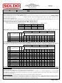
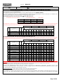
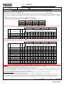
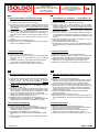
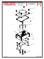
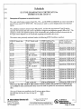
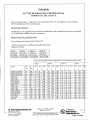
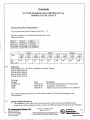
LIMIT SWITCH BOXES
Series SIB
Table of Contents – Indice dei contenuti - Inhaltsverzeichnis - Table des matières
Page
Pagina
Seite
Page
§
§
§
§
§
§
§
§
§
§
§
§
§
§
§
§
§
§
§
§
Safety instructions
Istruzioni di sicurezza
Sicherheitsinstruktionen
Instructions de sécurité
Conformity declaration
Dichiarazione di conformità
Konformitätserklärung
Déclaration de conformité
Installation & operating manual
Manuale di istallazione e uso
Installations- und Betriebsanleitung
Manuel d’installation et d’utilisation
Nomenclature
Codifica opzioni
Typenschlüssel
Codification des variantes, nomenclature
EC type examination certificate
Certificato di esame EC di tipo
EG-Baumusterprüfbescheinigung
Certificat type d’examen CE
2
6
7
11
13
Soldo S.r.l.
Via Monte Baldo, 60
25015 Desenzano d/G (Brescia) Italy
Tel +39 030 999.13.09 FAX +39 030 914.19.77
http: //www.soldo.net e-mail: [email protected]
Soldo reserves the right to change without notice
Soldo S.r.l.
Via Monte Baldo, 60
25015 Desenzano d/G (Brescia) Italy
Tel +39 030 999.13.09 - Fax +39 030 914.19.77
http: //www.soldo.net
e-mail: [email protected]
SI003-03
IT
Istruzioni di sicurezza per l’installazione in area pericolosa
Sigla dei modelli applicabili: limit switch box serie SI _ _ _ _ _ _-_ ( _ identifica diverse opzioni di configurazione corpo, tipo
switch, quantità, tipo morsetti, colore, ingressi cavi).
Le istruzioni che seguono sono applicabili alle apparecchiature che posseggono la certificazione ATEX n°: 03ATEX 135107X
1) I Limit switch box serie SI _ _ _ _ _ _-_ ( _ identifica diverse opzioni di configurazione corpo, tipo switch, quantità, tipo
morsetti, colore, ingressi cavi).
Possono essere installati in area pericolosa con presenza di gas, polveri, vapori e nebbie infiammabili gruppo IIC e con
classi di temperatura T4,T5,T6. Secondo quanto scritto nella tabella seguente:
II 2 G EEx ia IIC T6
1a) Categoria dell’apparato 2 G, identificazione EX :
Valutazione del circuito di alimentazione
Tipo Intrinsic Safety
Valori massimi
Type 1
Type 2
Type 3
Type 4
Uiii == 16 V
Uiii == 16 V
Uiii == 16 V
Uiii == 16 V
Ii = 25 mA
Ii = 25 mA
Ii = 52 mA
Ii = 76 mA
Pi = 34 mW Pi = 64 mW Pi = 169 mW Pi = 242 mW
Nella tabella sono mostrati, in funzione della assegnazione del tipo al circuito connesso, il legame alla massima
temperatura superficiale e al classe di temperatura così come la reattanza interna per i tipi di limit switch box indicati.
Type 1
Type 2
Type 3
Type 4
Maximum permissibile ambient temperature
Soldo
P +F
Ciii
L iii
in C° for application in temperature class
Code
switches code
(nF) (?H)
T6
T5
T4
T6
T5
T4
T6
T5
T4
T6
T5
T4
SI_20
SI_24
SI_59
SI_61
NJ4-12GK-N
NJ2-12GK-N
NCB2-12GK35-N0
NCN4-12GK35-N0
45 50
45 50
90 100
95 100
73
73
76
73
88
88
91
88
100
100
100
100
69
69
73
69
84
84
88
84
100
100
100
100
51
51
62
51
66
66
77
66
80
80
81
80
39
39
54
39
54
54
63
54
61
61
63
61
1b) Categoria dell’apparato 2 G/D , identificazione EX :
II 2 G/D EEx ia IIC T6
Nella tabella sono mostrati, in funzione della assegnazione del tipo al circuito connesso, il legame alla massima
temperatura superficiale e al classe di temperatura così come la reattanza interna per i tipi di limit switch box indicati.
Type 1
Soldo
Code
P +F
switches code
Ciii
L iii
(nF) (?H)
T6
Type 2
Type 3
Type 4
Maximum permissibile ambient temperature
in C° for application in temperature class
T5
T4
T6
T5
T4
T6
T5
T4
T6
T5
T4
SI_28
NJ2-11N-G
30 50
76
91 100 73
88 100 62
77 81
54
63 63
SI_30 NCB2-12GM35-N0 90 100 76
91 100 73
88 100 62
77 81
54
63 63
SI_36
NJ5-11-N-G
45 50
72
87 100 65
80 100 42
57 82
26
41 63
SI_37 NCN4-12GM35-N0 95 100 76
91 100 73
88 100 62
77 81
54
63 63
SI_39
NJ2-12GK-SN
50 150 73
88 100 69
84 100 51
66 80
39
54 61
SI_50
NJ2-11SN-G
50 150 76
91 100 73
88 100 62
77 81
54
63 63
SI_60
SJ-3.5-N
50 250 73
88 100 66
81 100 45
60 89
30
45 74
SI_62
SJ-3.5-SN
30 100 73
88 100 66
81 100 45
60 89
30
45 74
SI_63
SJ-3.5-S1N
30 100 73
88 100 66
81 100 45
60 89
30
45 74
SI_68
NJ5-11-N
45 50
72
87 100 65
80 100 42
57 82
26
41 63
SI_69
NJ2-11-N
45 50
73
88 100 66
81 100 45
60 89
30
45 74
SI_70
NJ2-V3-N
40 50
73
88 100 66
81 100 45
60 89
30
45 74
SI_84
NJ2-11-SN
50 150 73
88 100 66
81 100 45
60 89
30
45 74
SI_86
NJ4-12GK-SN
70 150 73
88 100 69
84 100 51
66 80
39
54 61
Incrociare i rating di funzionamento esposti con le temperature di funzionamento dei box riportate nei manuali di
installazione e uso.
2) L’installazione dovrà essere eseguita in accordo alle normative applicabili e da personale opportunamente addestrato.
3) Questa apparecchiatura non può essere riparata dall’utilizzatore.
4) Se sussiste la possibilità che l’apparecchiatura possa venire a contatto con sostanze aggressive, è responsabilità
dell’utilizzatore prendere le necessarie precauzioni per prevenire eventuali danni e assicurare che il grado di protezione
non venga compromesso.
Sostanze aggressive - es. Acidi, liquidi o gas, che possono attaccare l’housing del box.
5) Si dovrà osservare la seguente precauzione: Potrebbero, in rarissime occasioni, verificarsi sorgenti potenziali di innesco
dovute a scintille causate da urti o sfregamenti. Questo deve essere tenuto in considerazione quando l’apparecchio è
installato in area che richiede apparecchiature di gruppo II, categoria 2 G/D.
Pag. 2 of 21
ns. rif:
SI003-033
GB
Safety instruction to hazardous area installation
Model numbers covered: limit switch box series SI_ _ _ _ _ _-_ ( _ indicates options in housing configuration, switches,
switches quantity, terminal strip, box colour, cable entries).
The following instructions apply to equipment covered by ATEX certificate number 03ATEX 135107X
1) The SI limit switch box series may be used in an hazardous area with flammable gases, vapours, dust and mist, group
IIC, protection mode EEx ia with the following temperature classes T4,T5,T6.
1a) Device category 2G, EX identification
Evaluation and supply circuit
II 2 G EEx ia IIC T6
Type Intrinsic Safety
Max value
Type 1
Type 2
Type 3
Type 4
Uiii == 16 V
Uiii == 16 V
Uiii == 16 V
Uiii == 16 V
Ii = 25 mA
Ii = 25 mA
Ii = 52 mA
Ii = 76 mA
Pi = 34 mW Pi = 64 mW Pi = 169 mW Pi = 242 mW
The assignment of the type of the connected circuit to the maximum permissible temperature and the temperature class
as well as the effective internal reactances for the individual types of limit switch boxes are shown in the following table:
Type 1
Type 2
Type 3
Type 4
Maximum permissibile ambient temperature
Soldo
P +F
Ciii
L iii
in C° for application in temperature class
Code
switches code
(nF) (?H)
T6
T5
T4
T6
T5
T4
T6
T5
T4
T6
T5
T4
SI_20
SI_24
SI_59
SI_61
NJ4-12GK-N
NJ2-12GK-N
NCB2-12GK35-N0
NCN4-12GK35-N0
45 50
45 50
90 100
95 100
73
73
76
73
88
88
91
88
100
100
100
100
69
69
73
69
84
84
88
84
100
100
100
100
51
51
62
51
66
66
77
66
80
80
81
80
39
39
54
39
54
54
63
54
61
61
63
61
1b) Device category 2GD, EX identification
II 2 G/D EEx ia IIC T6
The assignment of the type of the connected circuit to the maximum permissible temperature and the temperature class
as well as the effective internal reactances for the individual types of limit switch boxes are shown in the following table:
Type 1
Soldo
Code
P +F
switches code
Ciii
L iii
(nF) (?H)
T6
Type 2
Type 3
Type 4
Maximum permissibile ambient temperature
in C° for application in temperature class
T5
T4
T6
T5
T4
T6
T5
T4
T6
T5
T4
SI_28
NJ2-11N-G
30 50
76
91 100 73
88 100 62
77 81
54
63 63
SI_30 NCB2-12GM35-N0 90 100 76
91 100 73
88 100 62
77 81
54
63 63
SI_36
NJ5-11-N-G
45 50
72
87 100 65
80 100 42
57 82
26
41 63
SI_37 NCN4-12GM35-N0 95 100 76
91 100 73
88 100 62
77 81
54
63 63
SI_39
NJ2-12GK-SN
50 150 73
88 100 69
84 100 51
66 80
39
54 61
SI_50
NJ2-11SN-G
50 150 76
91 100 73
88 100 62
77 81
54
63 63
SI_60
SJ-3.5-N
50 250 73
88 100 66
81 100 45
60 89
30
45 74
SI_62
SJ-3.5-SN
30 100 73
88 100 66
81 100 45
60 89
30
45 74
SI_63
SJ-3.5-S1N
30 100 73
88 100 66
81 100 45
60 89
30
45 74
SI_68
NJ5-11-N
45 50
72
87 100 65
80 100 42
57 82
26
41 63
SI_69
NJ2-11-N
45 50
73
88 100 66
81 100 45
60 89
30
45 74
SI_70
NJ2-V3-N
40 50
73
88 100 66
81 100 45
60 89
30
45 74
SI_84
NJ2-11-SN
50 150 73
88 100 66
81 100 45
60 89
30
45 74
SI_86
NJ4-12GK-SN
70 150 73
88 100 69
84 100 51
66 80
39
54 61
Cross the temperature rating shown with the limit switch box rating shown in limit switch box installation & operating
manual.
2) Suitably trained personnel shall carry out installation in accordance with applicable code of practice
3) The user should not repair this equipment.
4) If the equipment is likely to come into contact with aggressive substances, it is responsibility of the user to take suitable
precautions that prevent it from being adversely affected, thus ensuring that the type of protection is not compromised.
Agressive substances – es. Acidic liquids or gases that may attack the switch box housing.
5) The following precaution must be observed:
The metallic alloy used for the enclosure, in the event of a rare accident, could cause ignition sources due to impact or
friction (sparks may occur). This shall be considered when the box is installed in group II category 2 G/D areas.
Pag. 3 of 21
ns. rif:
SI003-033
DE
Sicherheitsinstruktion für Geräte in explosionsgefährdeten Bereichen
Modele mit der Bezeichnung SI_ _ _ _ _ _-_ ( _ zeigen Optionen von Schaltern, Schalter Qualitäten, Klemmleisten,
Gehäusefarben und Kabeleingängen).
Die folgende Instruktion gehört zu Geräten mit der ATEX Zertifikat Nummer 03ATEX 135107X
1) SI Endschalterboxen können in explosionsgefährdeten Bereichen mit brennbaren Gasen, Dämpfen und Stäuben der
Gruppe IIC bei folgenden Temperaturklassen eingesetzt werden T4,T5,T6.
1a) Gerätekategorie 2G, EX Kennzeichnung
Evaluation and supply circuit
II 2 G EEx ia IIC T6
Type Intrinsic Safety
Max value
Typ 1
Typ 2
Typ 3
Typ 4
Uiii == 16 V
Uiii == 16 V
Uiii == 16 V
Uiii == 16 V
Ii = 25 mA
Ii = 25 mA
Ii = 52 mA
Ii = 76 mA
Pi = 34 mW Pi = 64 mW Pi = 169 mW Pi = 242 mW
The assignment of the type of the connected circuit to the maximum permissible temperature and the temperature class
as well as the effective internal reactances for the individual types of limit switch boxes are shown in the following table:
Typ 1
Typ 2
Typ 3
Typ 4
Maximum permissibile ambient temperature
Soldo
P +F
Ciii
L iii
in C° for application in temperature class
Code
switches code
(nF) (?H)
T6
T5
T4
T6
T5
T4
T6
T5
T4
T6
T5
T4
SI_20
SI_24
SI_59
SI_61
NJ4-12GK-N
NJ2-12GK-N
NCB2-12GK35-N0
NCN4-12GK35-N0
45 50
45 50
90 100
95 100
73
73
76
73
88
88
91
88
100
100
100
100
69
69
73
69
84
84
88
84
100
100
100
100
51
51
62
51
66
66
77
66
80
80
81
80
39
39
54
39
54
54
63
54
61
61
63
61
1b) Gerätekategorie 2GD, EX Kennzeichnung
II 2 G/D EEx ia IIC T6
The assignment of the type of the connected circuit to the maximum permissible temperature and the temperature class
as well as the effective internal reactances for the individual types of limit switch boxes are shown in the following table:
Type 1
Soldo
Code
P +F
switches code
Ciii
L iii
(nF) (?H)
T6
Type 2
Type 3
Type 4
Maximum permissibile ambient temperature
in C° for application in temperature class
T5
T4
T6
T5
T4
T6
T5
T4
T6
T5
T4
SI_28
NJ2-11N-G
30 50
76
91 100 73
88 100 62
77 81
54
63 63
SI_30 NCB2-12GM35-N0 90 100 76
91 100 73
88 100 62
77 81
54
63 63
SI_36
NJ5-11-N-G
45 50
72
87 100 65
80 100 42
57 82
26
41 63
SI_37 NCN4-12GM35-N0 95 100 76
91 100 73
88 100 62
77 81
54
63 63
SI_39
NJ2-12GK-SN
50 150 73
88 100 69
84 100 51
66 80
39
54 61
SI_50
NJ2-11SN-G
50 150 76
91 100 73
88 100 62
77 81
54
63 63
SI_60
SJ-3.5-N
50 250 73
88 100 66
81 100 45
60 89
30
45 74
SI_62
SJ-3.5-SN
30 100 73
88 100 66
81 100 45
60 89
30
45 74
SI_63
SJ-3.5-S1N
30 100 73
88 100 66
81 100 45
60 89
30
45 74
SI_68
NJ5-11-N
45 50
72
87 100 65
80 100 42
57 82
26
41 63
SI_69
NJ2-11-N
45 50
73
88 100 66
81 100 45
60 89
30
45 74
SI_70
NJ2-V3-N
40 50
73
88 100 66
81 100 45
60 89
30
45 74
SI_84
NJ2-11-SN
50 150 73
88 100 66
81 100 45
60 89
30
45 74
SI_86
NJ4-12GK-SN
70 150 73
88 100 69
84 100 51
66 80
39
54 61
Cross the temperature rating shown with the limit switch box rating shown in limit switch box installation & operating
manual.
2) Die Installation dieser Geräte darf nur durch entsprechend geschultes Personal vorgenommen werden.
3) Der Betreiber darf an den Geräten keine Reparaturen vornehmen.
4) Wenn die Möglichkeit besteht, dass die Geräte in Kontakt mit aggressiven Substanzen kommen, ist es in der
Verantwortung des Betreibers sicherzustellen, dass die nötigen Schutz- und Vorsichtsmaßnamen getroffen werden, damit
die Geräte nicht in Mitleidenschaft gezogen werden.
Agressive Substanzen – Wie. Säuren, Laugen oder Gase die Metall angreifen .
5) Die folgenden Vorsichtsmassnahmen müssen berücksichtigt werden:
Die metallische Legierung des Gehäuses, könnte in seltenen Ausnahmefällen, bei Schlägen oder Reibung die Ursache von
Funken sein. Das muss berücksichtigt werden, wenn die Endschalterbox in Zonen der Gruppe II Kategorie 2G/D installiert
wird.
Pag. 4 of 21
ns. rif:
SI003-033
FR
Instructions de sécurité pour les installations en zone dangereuse
Codes des modèles utilisables SI_ _ _ _ _ _-_ avec diverses options de micro interrupteurs, quantité de micro interrupteurs
installée, borniers, couleurs, presse-étoupes.
Les instructions suivantes concernent les appareillages qui ont la certification ATEX numéro 03ATEX 135107X
1) Les boîtiers fin de course de la série SI peuvent être installées dans les zones dangereuses avec présence de gaz, de
vapeur ou de poussières inflammables du groupe IIC et avec les classes de température T4,T5,T6 comme de la table
suivante :
II 2 G EEx ia IIC T6
1a) Catégorie de dispositif 2G, EX identification
Evaluation and supply circuit
Type Intrinsic Safety
Max value
Type 1
Type 2
Type 3
Type 4
Uiii == 16 V
Uiii == 16 V
Uiii == 16 V
Uiii == 16 V
Ii = 25 mA
Ii = 25 mA
Ii = 52 mA
Ii = 76 mA
Pi = 34 mW Pi = 64 mW Pi = 169 mW Pi = 242 mW
The assignment of the type of the connected circuit to the maximum permissible temperature and the temperature class
as well as the effective internal reactances for the individual types of limit switch boxes are shown in the following table:
Type 1
Soldo
Code
P +F
switches code
Ciii
L iii
(nF) (?H)
SI_20
SI_24
SI_59
SI_61
NJ4-12GK-N
NJ2-12GK-N
NCB2-12GK35-N0
NCN4-12GK35-N0
45 50
45 50
90 100
95 100
Type 2
Type 3
Type 4
Maximum permissibile ambient temperature
in C° for application in temperature class
T6
T5
T4
T6
T5
T4
T6
T5
T4
T6
T5
T4
73
73
76
73
88
88
91
88
100
100
100
100
69
69
73
69
84
84
88
84
100
100
100
100
51
51
62
51
66
66
77
66
80
80
81
80
39
39
54
39
54
54
63
54
61
61
63
61
1b) Catégorie de dispositif 2G, EX identification
II 2 G/D EEx ia IIC T6
The assignment of the type of the connected circuit to the maximum permissible temperature and the temperature class
as well as the effective internal reactances for the individual types of limit switch boxes are shown in the following table:
Type 1
Type 2
Type 3
Type 4
Maximum permissibile ambient temperature
Soldo
P +F
Ciii
L iii
in C° for application in temperature class
Code
switches code
(nF) (?H)
T6
T5
T4
T6
T5
T4
T6
T5
T4
T6
T5
T4
SI_28
NJ2-11N-G
SI_30 NCB2-12GM35-N0
SI_36
NJ5-11-N-G
SI_37 NCN4-12GM35-N0
SI_39
NJ2-12GK-SN
SI_50
NJ2-11SN-G
SI_60
SJ-3.5-N
SI_62
SJ-3.5-SN
SI_63
SJ-3.5-S1N
SI_68
NJ5-11-N
SI_69
NJ2-11-N
SI_70
NJ2-V3-N
SI_84
NJ2-11-SN
SI_86
NJ4-12GK-SN
30
90
45
95
50
50
50
30
30
45
45
40
50
70
50
100
50
100
150
150
250
100
100
50
50
50
150
150
76
76
72
76
73
76
73
73
73
72
73
73
73
73
91
91
87
91
88
91
88
88
88
87
88
88
88
88
100
100
100
100
100
100
100
100
100
100
100
100
100
100
73
73
65
73
69
73
66
66
66
65
66
66
66
69
88
88
80
88
84
88
81
81
81
80
81
81
81
84
100
100
100
100
100
100
100
100
100
100
100
100
100
100
62
62
42
62
51
62
45
45
45
42
45
45
45
51
77
77
57
77
66
77
60
60
60
57
60
60
60
66
81
81
82
81
80
81
89
89
89
82
89
89
89
80
54
54
26
54
39
54
30
30
30
26
30
30
30
39
63
63
41
63
54
63
45
45
45
41
45
45
45
54
63
63
63
63
61
63
74
74
74
63
74
74
74
61
Cross the temperature rating shown with the limit switch box rating shown in limit switch box installation & operating
manual.
2) L’installation devra être réalisée suivant les normes en vigueur et avec du personnel agrée
3)Cet appareillage ne pourra faire l’objet de réparation par l’utilisateur.
4) S’il subsiste la possibilité que l’appareillage puisse se trouver en contact avec des substances agressives, il est de la
responsabilité de l’utilisateur de prendre les précautions nécessaires pour prévenir des dommages éventuels et de
s’assurer que le degré de protection ne sera pas compromis.
Substances agressives , par exemple: des acides, liquides ou gazeux qui peuvent attaquer les métaux..
5) Les précautions suivantes devront être observées :
Il est possible de vérifier dans des occasions rarissimes que l’alliage métallique utilisé pour le boîtier peut devenir une
source potentielle d’allumage due à des impacts ou une friction avec formation éventuelle d’étincelle. Ceci doit être pris
en considération lorsque le matériel est installé en zone qui demande un appareillage du groupe II catégorie 2G/D.
Document: SI003-03 Issued by: AM Date: 07/06/2004
Pag. 5 of 21
Soldo srl
via Monte Baldo, 60
25015 Desenzano d/G (BS) - Italy
www.soldo.net
IT
tel 030 - 999.13.09
fax 030 - 914.19.77
E mail [email protected]
GB
Dichiarazione di conformità ai sensi della
direttiva Atex 94/9/EC
Declaration of conformity as defined by the
ATEX directive 94/9/EC
Dichiariamo, sotto la nostra responsabilità, che i
SOLDO “limit switch box SIA,SIB,SIC,SIF,SIP,SIS series”,
II 2 G EEx ia IIC T6 to T4
or
II 2 G/D EEx ia IIC T6 to T4
(a seconda delle opzioni di proximity) sono conformi
alle disposizioni delle direttive ATEX 94/9/EC
“Equipment or Protective Systems intended for use in
potentially
explosive
atmospheres”
e
con
l’adempimento della legislazione nazionale. Inoltre
dichiariamo che sono state applicate le norme:
Herewith we declare that the SOLDO “limit switch box
SIA,SIB,SIC,SIF,SIP,SIS series,
II 2 G EEx ia IIC T6 to T4
or
II 2 G/D EEx ia IIC T6 to T4
(according to proximity switches options) are in
conformity with the provision of the ATEX directive
94/9/EC “Equipment or Protective Systems intended
for use in potentially explosive atmospheres” and with
national
implementing
legislation
and
that
appropriate harmonized standards have been
applied:
EN 50014 1997 +A1/A2
EN 50020 2003
89/336/CEE - 1989
EN 50014 1997 +A1/A2
EN 50020 2003
89/336/CEE - 1989
EC- Certificato di controllo Tipico
03 ATEX 135107X
EC- Type examination certificate
03 ATEX 135107X
Notifica della assicurazione qualità
Ul Demko Q135510
Production quality assurance notification:
Ul Demko Q135510
FR
DE
Déclaration of con formity as defined by Atex
directive 94/9/EC
Konformitätserklärung im Sinne der ATEX
richtlinie 94/9/EC
Par la présente nous déclarons que les SOLDO“ limit
switch box SIA,SIB,SIC,SIF,SIP,SIS series ‘’,
II 2 G EEx ia IIC T6 to T4
or
II 2 G/D EEx ia IIC T6 to T4
(selon les proximity switches options) sont conformes
aux dispositions des Directive ATEX 94/9/EC
“Equipment or Protective Systems intended for use in
potentially explosive atmospheres” et aux législations
nationales les transposant. Les normes applicables
sont:
Hiermit erklären wir, dass die SOLDO “limit switch box
SIA,SIB,SIC,SIF,SIP,SIS series”,
II 2 G EEx ia IIC T6 to T4
or
II 2 G/D EEx ia IIC T6 to T4
(sowie den ATEX 94/9/EC “Equipment or Protective
Systems intended for use in potentially explosive
atmospheres” und den einschlägigen nationalen
durchführungsbestimmungen entsprechen.
Folgende normen wurden zugrundegelegt:
EN 50014 1997 +A1/A2
EN 50020 2003
89/336/CEE - 1989
Attestation d’examen CE de type:
03 ATEX 135107X
Assurance qualité de production:
Ul Demko Q135510
EN 50014 1997 +A1/A2
EN 50020 2003
89/336/CEE - 1989
EG- Baumusterprüfbescheinigung:
03 ATEX 135107X
Anerkennung Qualitätssicherung der Produktion:
Ul Demko Q135510
Document: CE003-03 Issued by: AM
Rev. 2 Date: 07/06/04
Pag. 6 of 21
Soldo S.r.l.
Via Monte Baldo, 60
25015 Desenzano d/G (Brescia) Italy
Tel +39 030 999.13.09 - Fax +39 030 914.19.77
http: //www.soldo.net
e-mail: [email protected]
GB
Installation & Operating Manual
Manuale d’installazione
Installations und Betriebsanleitung
Manuel d’installation et d’utilisation
IOM-SIB 00-02
SIB
IT
READ THIS INSTRUCTION FIRST
PRIMA DI INSTALLARE IL BOX LEGGERE QUESTE ISTRUZIONI
To avoid serious or fatal personal injury or major property
damage, read and follow all safety instruction in this manual.
If you require additional assistance, please contact the
manufacturer.
Per evitare il ferimento, la morte o danni importanti a oggetti
leggere e seguire tutte le istruzioni di sicurezza presenti in
questo manuale. Se vi servono informazioni aggiuntive non
esitate a contattate il produttore.
SAVE THIS INSTRUCTION
CONSERVATE QUESTE ISTRUZIONI
SAFETY ALERT SYMBOLS
SIMBOLI DI SEGNALAZIONE PERICOLO
DANGER Warns of hazard that WILL cause serious personal
injury, death or major property damage.
WARNING Warns of hazard that MAY cause serious personal
injury, death or major property damage.
CAUTION Warns of hazard that MAY cause personal injury or
property damage.
DANGER Segnalazione di pericolo che causerà serie ferite, morte
o danni importanti a oggetti.
WARNING Segnalazione di pericolo che potrà causare serie ferite,
morte o danni importanti a oggetti.
CAUTION
Segnalazione di pericolo che potrà causare ferite o
danni a oggetti.
WARNING !
HAZARDOUS VOLTAGE. Disconnect all power before servicing
equipment. DO NOT REMOVE COVER WHEN ENERGISED.
CAUTION !
WARNING !
PERICOLO SCOSSE ELETTRICHE. Togliere l’alimentazione elettrica
prima di collegare o manutenere l’apparecchio. NON TOGLIERE LI
COPERCHIO CON L’APPARECCHIO IN TENSIONE
CAUTION !
Do not exceed the limit switch performance limitation. Exceeding
the limitation may cause damage to the limit switch, actuator and
valve.
The conduit plug supplied with the switch boxes are for transit
purposes only. IP67 protection depends on cable gland and cabling
methods used.
Limit switchbox for quarter-turn valve device (90° rotation).
Maximum shaft angular velocity 250 rpm.
Follow switch adjustment & indicator setting before servicing the
limit switch box.
Non superare le limitazioni di utilizzo degli switch. Il superamento
delle limitazioni può causare il danneggiamento degli switch, dell’
attuatore o della valvola.
I tappi di protezione dell’ingresso cavi forniti a corredo di ogni switch
box servono solo come protezione durante il trasporto e non
garantiscono il grado di protezione IP 67. Vanno pertanto sostituiti, in
fase di installazione, con pressa cavo che garantiscano il grado di
protezione richiesto.
Limit switch box per uso su valvole a quarto di giro (90° di rotazione).
Massima velocità di rotazione dello stelo 250 rpm. Non rispettando
questa indicazione si producono danni.
Seguire la procedura di taratura camme e regolazione indicatore
prima di mettere in servizio il limit switch box.
1e INSTALLATION
1i INSTALLAZIONE SULL’ATTUATORE
1.1 Attach proper mounting bracket (1) to the box (4) housing
using four M6X8 bolts (2).
1.2 Align shaft (5) to actuator shaft and engage it.
1.3 Attach bracket to actuator using hardware provided (3).
1.1 Fissare la staffa (1) al corpo del box (4) utilizzando le 4 viti a
cava esagonale M6x8 (2).
1.2 Ruotare manualmente lo stelo (5) in modo che il lembo fresato
sia parallelo alla cava situata sul pignone dell’attuatore, quindi
innestarlo alla stessa.
1.3 Fissare la staffa (1) all’attuatore con le viti fornite a corredo (3).
IOM-SIB00-02
Pag. 7 of 21
Soldo S.r.l.
Via Monte Baldo, 60
25015 Desenzano d/G (Brescia) Italy
Tel +39 030 999.13.09 - Fax +39 030 914.19.77
http: //www.soldo.net
e-mail: [email protected]
DE
Installation & Operating Manual
Manuale d’installazione
Installations und Betriebsanleitung
Manuel d’installation et d’utilisation
IOM-SIB 00-02
SIB
FR
LESEN SIE ZUERST DIESE INSTRUKTIONEN
LIRE LES INSTRUCTIONS AVANT D’INSTALLER LE BOITIER FIN
DE CORSE
Zur Vermeidung von gravierenden Personenschäden oder
Schäden am Gerät, lesen und befolgen Sie alle
Sicherheitsinstruktionen in dieser Anleitung. Wenn Sie
zusätzliche Hilfe benötigen, kontaktieren Sie bitte den
Hersteller.
Il est important de suivre les instructions contenues dans ce
manuel pour éviter tout dommage corporel ou matériel eventuel.
Si vous désirez des informations complémentaires n’hésitez pas
à nous contacter.
BEWAHREN SIE DIESE INSTRUKTIONEN AUF
CES INSTRUCTIONS DOIVENT ETRE CONSERVEES
SICHERHEITS- UND WARNSYMBOLE
SYMBOLES DES SIGNAUX D’ALERTE
DANGER Warnt vor Gefahren welche für Menschen gravierende
Folgen, schwere Unfälle oder Tod zur folge haben.
WARNING Warnt vor Gefahren welche für Menschen gravierende
Folgen, schwere Unfälle oder Tod zur folge haben können.
CAUTION Warnt vor Gefahren welche für Menschen gravierende
Folgen oder schwere Unfälle zur folge haben können.
DANGER Signale que le non respect causera des dommages
corporels ou matériels importants.
WARNING Signale que le non respect peut causer des dommages
corporels ou matériels.
CAUTION Signale que le non respect peut causer des dommages
matériels.
WARNUNG !
GEFÄHRLICHE SPANNUNG Wegen der Gefahr eines
Elektroschocks, müssen alle Spannungsführenden Elemente vor
jeder Manipulation vom Netz getrennt werden.
WARNUNG !
WARNING !
CHOC ÉLECTRIQUE. Pour éviter le risque de choc électrique couper
l’alimentation avant de raccorder les fils ou pour assurer une
maintenance. NE PAS ENLEVER LE COUVERCLE AVEC LE
BOITIER SOUS TENSION.
CAUTION !
Überschreiten Sie nie die Leistungsgrenzen des Endschalters. Das
Überschreiten der Leistungsgrenzen kann zu Beschädigungen am
Endschalter führen.
Die Verschlussdeckel für die Kabeleingänge im Gehäuse sind nur
für den Transport. IP67 Schutz ist abhängig von den richtigen
Kabelverschraubungen.
Die Endschalterbox ist für 90° Drehantriebe. Max. erlaubte
Schaltgeschwindigkeit
250 rpm. Das Nicht-Beachten dieser
Vorgaben, führt zu Beschädigungen.
Befolgen Sie die Einstellung Endschalter 2d bevor Sie die
Endschalterbox benützen.
Ne pas dépasser les limites d’utilisation des micro-interrupteurs. En
cas contraire, ils peuvent être endommagés.
Le boîtier fin de course s’utilise pour des vannes au quart de tour
(90°). La vitesse de rotation maximum de l’axe est de 250 t /mn. Une
vitesse supérieure peut créer des dommages.
Le bouchon de protection fourni avec les boîtiers est fait pour assurer
une protection pendant le transport. Ils n’est pas en mesure d’assurer
une protection IP67. Il sera substitué par un presse étoupe donnant la
protection appropriée.
Suivre la procédure de réglage de la came et de l’indicateur avant de
mettre en service le boîtier fin de course.
1d MONTAGE AUF DEN ANTRIEB
1f MONTAGE SUR L’ACTIONNEUR
1.1 Verwenden
Sie
passende
Montagebügel
(1)
fürs
Schaltergehäuse (4) verwenden Sie 4 M6x8 Schrauben (2).
1.2 Richten Sie die Achse (5) zur Antriebsachse aus und
verbinden Sie diese.
1.3 Befestigen Sie den Montagebügel (1) mit den mitgelieferten
Schrauben und U-Scheiben (3).
1.1 Fixer le support (1) au boîtier (4) en utilisant les 4 vis tête
hexagonales M6x8 (2).
1.2 Aligner l’axe (5) en fonction de l’axe de l’actionneur et engager
l’un dans l’autre.
1.3 Fixer le support (1) sur l’actionneur en utilisant les vis fournies
(3)-
IOM-SIB00-02
Pag. 8 of 21
Soldo S.r.l.
Via Monte Baldo, 60
25015 Desenzano d/G (Brescia) Italy
Tel +39 030 999.13.09 - Fax +39 030 914.19.77
http: //www.soldo.net
e-mail: [email protected]
Installation & Operating Manual
Manuale d’installazione
Installations und Betriebsanleitung
Manuel d’installation et d’utilisation
IOM-SIB 00-02
SIB
GB
IT
2e SWITCH ADJUSTMENT & 3D INDICATOR SETTING
2i REGOLAZIONE DEI FINECORSA & REGOLAZIONE DEL L’ INDICATORE 3D.
2.1 Loose the screws (8) and remove box cover (7).
2.2 Remove screw (10) and lift up 3D ni dicator from its splined
retainer. Attention keep indicator (9) hand gripped when loosing
and tightening screw (10) Do not rotate indicator when engaged
onto retrained.
2.3 Follows indication in “Cams setting ” Page 10
2.4 Box with 3-4 switches, set the actuator in the extra position you
have to signal. Act according to indications in “Cams setting –
Regolazione delle Camme” to set cams of the switch number 3
and 4.
2.5 Set 3D indicator (9) on splined retainer according to valve
position.
2.6 Fix 3D indicator screwing the (10) screw.
2.7 Replace box cover (7). WARNINGS: check seal (6) is properly
fitted in slot. Tightening screws (8).
1.1 Svitare le quattro viti (8) e rimuovere il coperchio (7).
1.2 Togliere la vite (10) e sfilare l’indicatore 3D dal supporto
millerighe. Attenzione: tenere l’indicatore (9) ben fermo quando si
svita e si riavvita la vite (10) Non ruotare l’indicatore 3D quando
innestato nel mille righe.
1.3 Seguire le indicazioni della tabella “Cams setting – Regolazione
delle Camme” page 10.
1.4 Se box con 3-4 micro, portare l’attuatore nelle altre posizioni in
cui si desiderano le segnalazioni. Regolare le camme per i micro
3 e 4 agendo come da indicazioni della tabella “Regolazione delle
Camme”.
1.5 Posizionare l’indicatore 3D sul supporto millerighe in modo da
rispecchiare la posizione della valvola.
1.6 Fissare l’indicatore 3D serrando la vite (10).
1.7 Riposizionare il coperchio (7) sul box (4). ATTENZIONE verificare
che la guarnizione (6) si alloggiata nella apposita cava. Serrare le
viti (8).
3e ELECTRICAL WIRING
3i CABLAGGIO ELETTRICO
3.1 Remove cover (7) according point 2.1.
3.2 Remove protection plugs from cable entries and substitute them
with cable glands or plugs suitable for type of protection
required.
3.3 Connect terminal strip (14) according to the wiring diagram in
“Cams setting – Regolazione delle Camme” Page 10.
3.4 Reassemble cover (7) according to points 2.5,2.6 and 2.7.
3.1 Rimuovere il coperchio (7) come indicato nel punto 2.1.
3.2 Rimuovere i tappi di protezione e sostituirli con pressacavo/i ed/o
tappo/i filettati, che garantiscano il livello di protezione richiesto.
3.3 Collegare i morsetti (14) utilizzando un cacciavite con testa a
taglio max. 3,5 mm e seguendo lo schema corrispondente.
3.4 Rimontare il coperchio (7) come indicato nei punti 2.5,2.6 e 2.7.
DE
FR
2d EINSTELLUNG ENDSCHALTER- UND STELLUNGSANZEIGE
2f REGLAGE DES FINS DE COURSE ET DE L’INDICATEUR DE
POSITION
1.1 Lösen Sie die Schrauben (8) und entfernen Sie den Deckel (7).
1.2 Entfernen Sie die Schraube (10) und heben Sie den 3D
Indikator (9) aus seiner Zahnwellen Befestigung. Achtung:
Drehen Sie nicht den 3D Indicator wenn er mit der Zahnwelle
verbunden ist
1.3 Befolgen Sie die Angaben in “ “Einstellung Nocken /
Schaltfahnen“ (Seite 10).
1.4 Für Boxen mit 3-4 Schaltern, stellen Sie den Antrieb auf die
extra Positionen von denen das Signal benötigt wird. Befolgen
Sie die Angaben in “Einstellung Nocken / Schaltfahnen “ (Seite
10) um die “Schaltfahne“ von Schalter 3 & 4 einzustellen.
1.5 Setzen Sie den 3D Indikator auf die richtige Position der
Verzahnung passend zur Armaturenposition.
1.6 Befestigen Sie den 3D Indikator mit der Schraube (10).
1.7 Montieren Sie den Gehäusedeckel (7). WARNUNG: prüfen Sie
die Dichtung (6), sitzt sie korrekt im vorgesehenen Schlitz.
1.1 Dévisser les 4 vis (8) et enlever le capot (7).
1.2 Enlever la vis (10) et sortir l’indicateur 3D (9) du support cannelé.
Attention: tenir fermement l’indicateur 3D lorsque on le monte ou
le démonte. Ne pas le faire tourner sur son support cannelé.
1.3 Suivre les indications du tableau : réglage des cames page 10.
1.4 Boîtier avec 3 ou 4 micro-interrupteurs, régler d’abord l’actionneur
en fonction de la position en plus de la normale. Puis régler les
cames pour les micro 3 et 4 en agissant comme indiqué dans le
tableau ‘’réglage des cames’’.
1.5 Positionner l’indicateur 3D sur le support cannelé suivant la
position de la vanne.
1.6 Fixer l’indicateur 3D en serrant la vis (10).
1.7 Remettre le capot (7) sur le boîtier (4). Attention:bien vérifier que
le joint d’étanchéité (6) du capot est bien positionné. Serrer les vis
(8).
3d ELEKTRISCHE VERKABELUNG
3f CABLAGE ELECTRIQUE
3.1 Entfernen Sie den Deckel (7) gemäß Punkt 2.1.
3.2 Entfernen Sie die Schutzkappen von den Kabeleingängen und
bestücken Sie diese mit der passenden Kabelverschraubung
mit der gew ünschten Abdichtung.
3.3 Verbinden Sie die Kabelklemme (14) gemäß dem
Kabeldiagramm in “Einstellung Nocken / Schaltfahnen“ (Seite
10.)
3.4 Montieren Sie den Deckel (7) gemäß den Angaben unter Punkt
2.5, 2.6 und 2.5.
3.1 Enlever le couvercle (7) comme indiqué au point 2.1.
3.2 Enlever le bouchon de protection et installer des presse étoupes
garantissant le degré de protection souhaitée.
3.3 Raccorder les bornes (14) suivant le schéma électrique du
tableau ‘’mise en place et réglage des cames’’ page 10.
3.4 Remonter le couvercle (7) comme indiqué au point 2.5, 2.6 et 2.7.
IOM-SIB00-02
Pag. 9 of 21
Soldo S.r.l.
Via Monte Baldo, 60
25015 Desenzano d/G (Brescia) Italy
Tel +39 030 999.13.09 - Fax +39 030 914.19.77
http: //www.soldo.net
e-mail: [email protected]
Wiring diagram
Model
Installation & Operating Manual
Manuale d’installazione
Installations und Betriebsanleitung
Manuel d’installation et d’utilisation
IOM-SIB 00-02
SIB
Cams setting / Regolazione camme / Réglage des cames / Einstellung Nocken/Schaltfahnen
Turn actuator pinion clockwise
Far ruotare il pignone dell'attuatore in senso orario
Die Antriebswelle im Uhrzeigersinn drehen.
Faire tourner le pignon de l'actionneur en sens horaire
1
Turn actuator pinion counter clockwise
Far ruotare il pignone dell'attuatore in senso antiorario
Die Antriebswelle entgegen dem Uhrzeigersinn drehen.
Faire tourner le pignon de l'actionneur en sens anti - horaire
4
BOTTOM
(CW)
TOP
(CCW)
S*2028(7)X-X
S*2428(7)X-X
S*2828(7)X-X
S*3028(7)X-X
S*3628(7)X-X
S*3728(7)X-X
S*3928(7)X-X
S*5028(7)X-X
S*5928(7)X-X
S*6128(7)X-X
S*6828(7)X-X
S*6928(7)X-X
S*8428(7)X-X
S*8628(7)X-X
5
2
Disingage cam from splined retrainer.
Spostare la camma fino a disinnestarla dal millerighe
Die Nocke nach oben verschieben bis sie aus der Wellenverzahnung
ausgekuppelt werden kann.
Désengager la came de l'axe cannelé.
Disingage cam from splined retrainer.
Spostare la camma fino a disinnestarla dal millerighe
Die Nocke nach unten verschieben bis sie aus der Wellenverzahnung
ausgekuppelt werden kann.
Désengager la came de l'axe cannelé.
EXTRA
POLES
(optional)
3
6
Turn, in the way shown, until switch is activated, then engage into splined retrainer.
Ruotarla, nella direzione indicata, fino a che fino all'azionamento dell'interruttore, poi reinserirla nel mille righe.
Die Nocke drehen, bis der Schalter aktiviert ist, danach wieder in die Wellenverzahnung einfuegen
Tourner dans le sens indiqué jusqu'au moment du fonctionnement du micro, puis remettre la came sur l'axe cannelé.
S*7022X-X
TOP
(CCW)
BOTTOM
(CW)
2
5
EXTRA
POLES
3
6
Right / ccw
Left / cw
S*6028(7)X-X
S*6228(7)X-X
EXTRA
POLES
(optional)
2-3
S*6328(7)X-X
IOM-SIB00-02
EXTRA
POLES
(optional)
Loosen (using a 19 wrench) top nut
Rotate cam and fit in front of sensor.
Allentare (chiave 19) il dado superiore
Ruotare la camma per portarla di fronte al sensore
Die obere Schraubenmutter lockern
(Schraubenschluessel 19).Die Schaltfahne drehen
und im Schlitz des Sensors befestigen.
Dévisser (clé de 19) l'ecrou du dessus.
Faire tourner la came pour la mettre
en face du capteur
5
Rotate cam (shown in drawing)
and fit in front of sensor
Ruotare la camma indicata
per portarla di fronte al sensore
Die Schaltfahne drehen und im Schlitz
des Sensors befestigen.
Faire tourner la came (indiquè dans le schéma)
pour la mettre en face du capteur
6
Fasten (using a 19 wrench) top shaft nut
Serrare (chiave 19) il dado superiore
Die obere Schraubenmutter
festziehen (Schraubenschluessel 19).
Serrer (clé de 19) l'ecrou supérieur.
Pag. 10 of 21
Soldo S.r.l.
Via Monte Baldo, 60
25015 Desenzano d/G (Brescia) Italy
Tel +39 030 999.13.09 - Fax +39 030 914.19.77
http: //www.soldo.net
e-mail: [email protected]
Installation & Operating Manual
Manuale d’installazione
Installations und Betriebsanleitung
Manuel d’installation et d’utilisation
IOM-SIB 00-02
SIB
NOMENCLATURE / CODIFICA VERSIONI / TYPENSCHLÜSSEL / CODIFICATION DES DIFFERENTES VERSIONS
SIB
20 2 0 1 - 1
Cable entry / Ingresso cavi / Kabel Eingang / Entrée de câble
0 n°2 PG 13.5
1 n°2 ½” npt
2 n°2 M20x1.5
Colour / Colore / Farbe / Couleur
0 Black
1 blue RAL 5015
Terminal strip / Morsettiera / Kabelklemme / Bornes
0 standard PCB + extra solenoid terminals
2 blue PCB + extra solenoid terminals
7 cage clamp blue + extra poles for solenoid valve
8 cage clamp blue
Switch quantity / Quantità switch / Anzahl Schalter / Nombre de micro interrupteurs
1 to 4 according switch type
Switch type
rating
Voltage
Min
Max resistive load Max inductive load
max qty
installed
sensibility 4 mm, current consumption : ≤1mA (face covered), ≥3mA (face not
P+F Nominal voltage
covered), self inductance ≤50 µH, self capacitance: ≤45 nF
U 0 = 8Vdc
temp. range -20°C ÷ +80°C
sensibility 2 mm, current consumption : ≤1mA (face covered), ≥3mA (face not
proximity NAMUR P+F Nominal voltage
covered), self inductance ≤50 µH, self capacitance: ≤45 nF
24 NJ2-12GK-N
U 0 = 8Vdc
temp. range -20°C ÷ +80°C
sensibility 2 mm, current consumption : ≤1mA (face covered), ≥3mA (face not
proximity NAMUR P+F Nominal voltage
covered), self inductance ≤50 µH, self capacitance: ≤30 nF
28 NJ2-11N-G
U 0 = 8Vdc
temp. range -20°C ÷ +80°C
sensibility 2 mm, current consumption : ≤1mA (f ace covered), ≥3mA (face not
proximity NAMUR P+F Nominal voltage
covered), self inductance ≤100 µH, self capacitance: ≤90 nF
30 NCB2-12GM35-N0 U 0 = 8Vdc
temp. range -20°C ÷ +80°C
sensibility 5 mm, current consumption : ≤1mA (face covered), ≥3mA (face not
proximity NAMUR P+F Nominal voltage
covered), self inductance ≤50 µH, self capacitance: ≤45 nF
36 NJ5-11N-G
U 0 = 8Vdc
temp. range -20°C ÷ +80°C
sensibility 4 mm, current consumption : ≤1mA (face covered), ≥3mA (face not
proximity NAMUR P+F Nominal voltage
covered), self inductance ≤100 µH, self capacitance: ≤95 nF
37 NCN4-12GM35-N0 U 0 = 8Vdc
temp. range -20°C ÷ +80°C
proximity NAMUR
sensibility 2 mm, current consumption : ≤1mA (face covered), ≥3mA (face not
Nominal voltage
covered), self inductance ≤150 µH, self capacitance: ≤50 nF
39 P + F
U 0 = 8Vdc
NJ2-12GK-SN
temp. range -20°C ÷ +80°C
proximity NAMUR
sensibility 2 mm, current consumption : ≤1mA (face covered), ≥3mA (face not
Nominal voltage
covered), self inductance ≤150 µH, self capacitance: ≤50 nF
50 P + F
U 0 = 8Vdc
NJ2-11SN-G
temp. range -20°C ÷ +80°C
proximity NAMUR
sensibility 2 mm, current consumption : ≤1mA (face covered), ≥3mA (face not
Nominal voltage
covered), self inductance ≤100 µH, self capacitance: ≤90 nF
59 P + F
U 0 = 8Vdc
NCB2-12GK35-N0
temp. range -20°C ÷ +80°C
sensibility 4 mm, current consumption : ≤1mA (face covered), 3mA (face not covered),
proximity NAMUR P+F Nominal voltage
self inductance ≤250 µH, self capacitance: ≤50 nF
60 SJ-3.5N
U 0 = 8Vdc
temp. range -20°C ÷ +80°C
sensibility 4 mm, current consumption : ≤1mA (face covered), 3mA (face not covered),
proximity NAMUR P+F Nominal voltage
self inductance ≤100 µH, self capacitance: ≤95 nF
61 NCN4-12GK35-N0 U 0 = 8Vdc
temp. range -20°C ÷ +80°C
sensibility 4 mm, current consumption : ≤1mA (face covered), ≥3mA (face not
proximity NAMUR P+F Nominal voltage
covered), self inductance ≤100 µH, self capacitance: ≤60 nF
62 SJ-3.5-SN
U 0 = 8Vdc
temp. range -20°C ÷ +80°C
sensibility 4 mm, current consumption : ≤1mA (face covered), ≥3mA (face not
proximity NAMUR P+F Nominal voltage
covered), self inductance ≤100 µH, self capacitance: ≤60 nF
63 SJ-3.5-S1N
U 0 = 8Vdc
temp. range -20°C ÷ +80°C
sensibility 5 mm, current consumption : ≤1mA (face covered), ≥3mA (face not
proximity NAMUR P+F Nominal voltage
covered), self inductance ≤50 µH, self capacitance: ≤45 nF
68 NJ5-11-N
U 0 = 8Vdc
temp. range -20°C ÷ +80°C
sensibility 2 mm, current consumption : ≤1mA (face covered), ≥3mA (face not cover)
proximity NAMUR P+F Nominal voltage
self inductance ≤50 µH self capacitance: ≤45 nF
69 NJ2-11-N
U 0 = 8Vdc
temp. range -20°C ÷ +80°C
sensibility 2 mm, current consumption : ≤1mA (face covered), ≥3mA (face not cover)
proximity NAMUR P+F Nominal voltage
70 NJ2-V3-N
self inductance ≤50 µH self capacitance: ≤40 nF
U 0 = 8Vdc
temp. range -20°C ÷ +80°C
sensibility 2 mm, current consumption : ≤1mA (face covered), ≥3mA (face not cover)
proximity NAMUR P+F Nominal voltage
84 NJ2-11-SN
self inductance ≤150 µH self capacitance: ≤50 nF
U 0 = 8Vdc
temp. range -20°C ÷ +80°C
sensibility 4 mm, current consumption : ≤1mA (face covered), ≥3mA (face not cover)
proximity NAMUR P+F Nominal voltage
86 NJ4-12GK-SN
self inductance ≤150 µH self capacitance: ≤70 nF
U 0 = 8Vdc
temp. range -20°C ÷ +80°C
proximity
NAMUR
20 NJ4-12GK-N
IOM-SIB00-02
2
2
2
2
2
2
2
2
2
2
2
2
2
3
2
3
2
2
Pag. 11 of 21
Soldo S.r.l.
Via Monte Baldo, 60
25015 Desenzano d/G (Brescia) Italy
Tel +39 030 999.13.09 - Fax +39 030 914.19.77
http: //www.soldo.net
e-mail: [email protected]
IOM-SIB00-02
Installation & Operating Manual
Manuale d’installazione
Installations und Betriebsanleitung
Manuel d’installation et d’utilisation
IOM-SIB 00-02
SIB
Pag. 12 of 21
Pag. 13 of 21
Pag. 14 of 21
Pag. 15 of 21
Pag. 16 of 21
Pag. 17 of 21
Pag. 18 of 21
Pag. 19 of 21
Pag. 20 of 21
Pag. 21 of 21