1
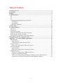
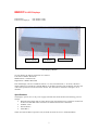
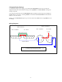
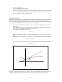
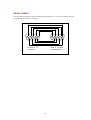
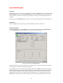
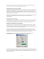
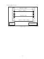
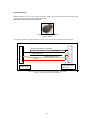
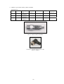
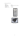
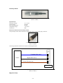
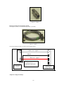
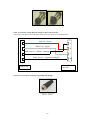
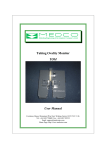
Data Acquisition Unit
Version 3.10
User Manual
Courtenay House, Monument Way East, Woking, Surrey GU21 5LY, U.K.
Tel: +44-1483-750600 Fax: +44-1483-762233
Email: [email protected]
Home Page: http://www.medcotas.com
Table of Contents
System Overview........................................................................................................ 3
Installation.................................................................................................................. 4
Displays ....................................................................................................................... 5
Communications ........................................................................................................ 7
S0 ............................................................................................................................. 9
S1 ............................................................................................................................. 9
S2 ............................................................................................................................. 9
Communicating through HyperTerminal............................................................... 10
Command........................................................................................................... 10
Explanation ........................................................................................................ 10
Calibrating Channels.............................................................................................. 11
Serial Cables ............................................................................................................. 12
Card Data Reader .................................................................................................... 13
Overview................................................................................................................ 13
Installation ............................................................................................................. 13
Using the program.................................................................................................. 13
Important Information about Storing Data ............................................................ 14
Preparing the card for new data ............................................................................. 14
Moving data to database files on the computer ..................................................... 14
Wiring Diagram for Acquisition Unit.................................................................... 17
Appendix – A: Coiled Tubing Applications .......................................................... 18
Shaft Encoder......................................................................................................... 19
Specifications:.................................................................................................... 19
Connectors for Shaft Encoder Cable: ................................................................ 19
Pressure Sensors .................................................................................................... 21
Electrical Connection for Pressure Sensors:...................................................... 21
Proximity Switch ................................................................................................... 24
Specifications:.................................................................................................... 24
Electrical Connection for Proximity Switch:..................................................... 24
Magnetic Pickup .................................................................................................... 24
Electrical Connection for Magnetic Pickup:...................................................... 25
Adaptor for Magnetic Pickup: ........................................................................... 25
Cable for Proximity Switch/Magnetic Pickup to Data Collection Unit: ........... 26
Connectors on Cable for Proximity Switch/Magnetic Pickup:.......................... 26
2
System Overview
The system is based on a microprocessor controller with a Motorola 68000 14 MHz processor as the
main controller. Analogue and counter signals are acquired and processed. The data is stored,
processed, and transmitted.
There are provisions for 8-8 bits and 8-12 bits analogue signals on the microprocessor board.
However, the MEDCO data acquisition system only uses 8-12 bits channels. An additional board is
utilised for the counter and quadrature signals. Provisions are for 4 counters and 1 quadrature shaft
encoder, all of which can be used.
Provisions are also made for storing number formats, gain, and offset values, lower and upper alarm
values for all the input channels. This information is used for the processing of the data and the
outputs. Furthermore, rates are computed for all the counters and the quadrature signals.
Three serial communication ports are provided. Currently, these are used for communicating with
displays and the computer. The third port is used for storing data on a S-RAM PC-MCIA card with a
capacity of 6 MByte.
3
Installation
Installation of the system is very simple and straightforward. The following steps should enable the
user to use the system.
•
Get the data acquisition unit out of the packaging.
•
Mechanically attach the sensors to your equipment. For coiled tubing equipment, the
recommended attachments are described in Appendix – A.
•
Connect the sensors to the data acquisition unit. All the analogue sensors are to be connected
to the analogue channels, i.e. circulating pressure, wellhead pressure, and weight to any of the
analogue channels 1 through to 8. Proximity switches are to be connected to any channel from
9 to 12 and finally shaft encoder to be connected to channel 13.
•
Connect to a mains power supply. The mains power supply is strictly what you ordered, i.e. if
you ordered 220 VAC then you should only use 220-250 VAC, and if you ordered 110 VAC
then you should only use 110-125 VAC. Alternatively, if you have a DC power then you may
use the Auxiliary power supply and connect it to 24 VDC. You can make 24 VDC power
supply using two car-batteries in series.
•
Connect your displays (supplied by MEDCO) to the serial port S0 using the serial link cable
supplied by MEDCO. The displays require power either as 220 VAC, 110 VAC, or 5 VDC.
•
Switch on the Data Acquisition Unit.
•
If you do not have a computer ready for the data acquisition, then the system will
automatically start in just over 1 minute.
•
If you have a computer ready to acquire data, then connect the computer using the supplied
serial cable to the serial port S1. You should have a program capable of communicating
through the serial port running on the computer, such as DART or HyperTerminal. The
system will wait for one minute before starting.
•
The system will now be running with all the factory default settings. The factory defaults are a
gain of unity and an offset value of zero for all the channels. All alarms are switched off.
Figure 1: Front view of the data acquisition unit – measures 23 x 20 x 16 cms (Part No. 10005)
4
Figure 1, shows the front side of the unit. This side has all the connections. Note the channel numbers
indicated on the picture. The channels are 1 through to 13 and increment from left to right and top to
bottom. The serial ports are also numbered as S0 through to S2 (from top to bottom).
The configuration of the system is as follows:
Channel
number
1 to 8
Sensor type
Comments
24 vdc excitation voltage.
12-bits resolution.
9 to 12
Analogue giving 0-10 vdc output or 0-5 vdc**
Pressure sensors, load cells, density meters, or any
analogue signal.
Proximity switch or magnetic pick-up
13
Quadrature shaft encoder
14 to 17
No connections
18
No connections
12 vdc excitation voltage.
Received pulses are conditioned
to be TTL compatible.
5 vdc excitation voltage.
Up/down counter.
Rates of channels 9-12
respectively.
Rate of channel 13.
**
The analogue channels inputs vary depending on the user choice of sensors. You should consult with
MEDCO if you need to know what voltage range is acceptable to your system.
Displays
It is important to note that , the displays use the same system for numbering as the data acquisition
unit, though the numbers appear in hexadecimals. The displays use address 00 for all displays to
respond to data, then addresses 01 (corresponds to address 1 in decimal) through to ff in hexadecimal
(corresponds to address 255 in decimal). Thus, to program a display to receive a signal from the data
acquisition unit, the display address should match the channel number.
To change the address of a display:
a. Move the flip switch number 3 to the OFF position to unlock the display, on the 2nd block of
flip switches from the left-hand-side. (See the rear view figure).
b. On the front of the display unit, press and hold the address button until the address of the
display unit appears.
c. Change the address using the up Δ or down ∇ button to increment or decrement the display
address until the required address is shown (in hexadecimal).
d. Press the OK button to accept.
e. Move the flip switch back to the locked position (ON), i.e. reverse step (a) above.
Example:
Suppose you have three displays and you wish to use them to display the counts of channel 9, the value
of channel 6, and the rate of channel 10 (corresponds to channel 15), then the displays should be
configured with the addresses 09, 06, and 0F respectively.
HINT: If you have difficulties converting decimal numbers to hexadecimal then use “Calculator” on
your computer to do the conversions for you. Enter the channel number in decimal then select the hex
option and the equivalent hexadecimal will be displayed. If the value is a one digit hexadecimal, then
simply add a zero to the left. Alternatively, simply count (in decimals) as you increment the address on
the display.
5
Rear view of display unit
INPUT
POWER
Earth
Rear of display panel
Neutral or DCLive or DC+
4
5
9
3
2
7
1
6
Wiring diagram of display unit connection to D-type connector
Front view of display unit (Part No. 06003)
6
MEDCO’s LED Displays
LED Display:
Enclosure (3 displays):
Part Number 17001
Part Number 17002
Menu button
Up button
Down button
3-LED Displays Module
On each display the buttons assignment is as follows:
Left button is MENU BUTTON
Middle button is UP BUTTON
Right button is DOWN BUTTON
Each LED display can have an address between 1 to 255 (in hexadecimal, i.e. 00 to FF). When the
display address corresponds to a channel address on the data acquisition unit, the display will show the
value of the parameter associated with the channel. The channels are numbered 1 through to 18 in
decimals.
Specifications
The displays operate on a 12 vdc power supply and in RS-485 mode and have the following protocol
settings:
• BAUD RATE: Either 9600 or 19200. When going through the menu, a baud rate of 9600 will
be shown as BAUD00 while a baud rate of 19200 will be shown as BAUD01.
• PARITY: None.
• DATA BITS: 8
• STOP BIT: 1
When used with the Data Acquisition unit, the baud rate needs to be set to 9600 (BAUD00).
7
Changing Display Settings
To change the settings on the display, press and hold the Menu Button for at least 2 seconds, the
display will show the current baud rate setting, use the Up Button or the Down Button to change the
settings if required.
To see the next menu item, press the Menu Button again, the display will show the current address is
hexadecimals (i.e. 00 to FF). Use the Up Button to increment and the Down Button to decrement the
address to the value desired.
Finally, press the Menu Button again to go to the next menu item, SAVE. Press the Up Button to save
the settings.
Wiring Diagrams
Power Connectors
Data Connectors
OUT - SOCKET
OUT - SOCKET
IN - PLUG
+12 vdc
Data signals A & B
1
2
6
3
7
4
8
5
9
5
4
9
IN - PLUG
3
8
2
1
1
4
6
7
2
Signal common
3
Looking inside the enclosure panel
Note: Wire colours may be different from those shown
8
1
4
3
2
Communications
All the communications with the data acquisition unit are achieved through the serial ports. These ports
are assigned specific tasks and cannot swapped or changed.
S0
The first serial port, S0, is used for communication with the displays. A serial link cable is supplied for
use with this port. The port is configured in RS-485 mode. The port configuration is as follows:
Baud rate:
Data bits:
Parity:
Stop bits:
Handshake:
9600
8
None
1
None
S1
The second serial port, S1, is used for communication with the computer. A serial link cable, supplied,
suitable for connecting to this port on one end (male side) and fitted with a female side for connecting
to the computer. This port is configured in RS-232 mode. This port is configured as follows:
Baud rate:
Data bits:
Parity:
Stop bits:
Handshake:
19200
8
None
1
Hardware (RTS/CTS)
Note that the handshake configuration is RTS/CTS. Thus, if you connect this to a computer, you must
run a communications program on the computer and configure the handshake as HARDWARE.
The user may use any program to capture the data. DART (Data Acquisition and Real Time processing
by MEDCO) is the recommended software to use with the data acquisition unit. DART is capable of
auto-detecting the unit and has several features that make communicating with the unit simple.
Alternatively, you may use a program such as Hyperterminal to communicate with the data acquisition
unit. To do this, follow these steps:
•
From your windows START button click PROGRAMS | ACCESSORIES |
COMMUNICATIONS | HYPERTERMINAL.
•
Double click the Hypertrm icon.
•
Give the session a name such as “MEDCO’s data acquisition unit”.
•
On the next screen use “CONNECT USING” and specify the appropriate com port, example
COM1.
•
On the next screen titled “PORT SETTINGS”, ensure that the bits per second is set to 19200
and the “FLOW CONTROL” is set to HARDWARE.
•
Allow a minute and then you should see the data coming from the data acquisition unit.
Alternatively, type the letter “q” in lower case and the system should start.
S2
The third serial port, S2 (RS-232 mode), can be used to write data to an S-RAM PC-MCIA card. The
data will be automatically logged onto the card and the baud rate setting is 19200.
9
Communicating through HyperTerminal
If you use HyperTerminal to communicate to the data acquisition unit, then you need to know the list
of commands and their functions.
When you enter HyperTerminal, you will only be receiving data. To stop the incoming data and
prepare the data acquisition unit to accept your commands, you will need to send the text “Trad”
followed by a carriage return (CR). The system will respond by issuing the characters “OK”. You are
now ready to change the system settings and the system is in the “PAUSE”. The following table
explains the available commands:
Command
“r” + CR
“e” + CR
“t” + CR
“g↔ ch↔ xxx.xxx” + CR
“o↔ ch↔ xxx.xxx” + CR
The command is a lower case letter “O”
“n↔ ch↔ xxx.xxx” + CR
“l↔ ch↔ xxx.xxx” + CR
The command is a lower case letter “L”
“u↔ ch↔ xxx.xxx” + CR
“L↔ ch” + CR
“U↔ ch” + CR
“c↔ ch” + CR
“i↔ ch↔ xxx.xxx” + CR
“s” + CR
“p” + CR
“C↔ WD↔ DD↔ MM↔ YYYY↔
hh↔ mm↔ ss” + CR
Explanation
Return to run mode – upon returning to run mode, all the
data in the RAM will be erased. Thus, you should use the
“transmit” command to retrieve the data before issuing
the “return” command.
Write settings table to EPROM. This command is
automatically issued when an “r” command is used.
Transmit the stored data from RAM
Set the gain for channel “ch” to “xxx.xxx”
Set the offset for channel “ch” to “xxx.xxx”
Set the number format for channel “ch” to “x” decimal
places. It is recommended that you do not use this option
as it is more or less redundant and the system will overwrite any number formats as necessary.
Set the lower alarm for channel “ch” to “xxx.xxx”
Set the upper alarm for channel “ch” to “xxx.xxx”
Remove the lower alarm for channel “ch”
Remove the upper alarm for channel “ch”
Calibrate channel “ch”. If the value of “ch” is greater
than 8, i.e. a counter or quadrature channel, then the
program will start counting the pulses and will stop when
a “k” is issued. Do not put a CR after the “k”. The
program will then issue the total counts.
If, on the other hand, the value of “ch” is between 1 and 8
then the readings will be reported continuously until “f”
command is issued.
Reset counter channel “ch” reading to “xxx.xxx”. The
value of “ch” must be between 9-13.
Reset all system settings to factory defaults, i.e. all gains
are 1, all offsets are 0, all alarms are off, and all number
formats are with 3 decimal places.
Print all the system settings. These will be in 18 lines
corresponding to channels 1-18 and will have the
following format:
“o=0.000 g=1.000 n=0.000”
Changes the date and time to:
Week day (0-6) = WD (Sunday = 0)
Day = DD
Month = MM
Year = YYYY
Hour = hh
Minute = mm
Second = ss
Notes:
•
↔ is a space
10
•
•
•
•
•
CR is the carriage return
All the commands are case sensitive
“ch” is channel number (1-18)
“xxx.xxx” is a value. The decimal point can be included anywhere within the value if needed.
To remove a channel output, simply change the gain of the channel to zero. To re-instate the
channel reset the gain to an appropriate value.
Calibrating Channels
Calibration is a procedure where a straight-line interpretation of the output signal is used to obtain the
equivalent physical values of the output signal. Thus, if we use a pressure sensor to measure the
pressure of a fluid ranging, say, from 0 to 5000 psi, and the sensor gives an output signal ranging from
0 to 10 vdc, then the calibration should be done in the following manner:
•
•
•
Take a low value reading (y1), usually the zero value is good enough. Monitor the output of
the sensor (x1).
Take a high value reading (y2), usually a value close to the maximum range of operation (i.e.
close to 5000 psi). Monitor the the output of the sensor (x2).
The straight-line relationship has the form
y = gx + o
•
Where “y” is the physical value, “x” is the monitored voltage, “g” is the gain, and “o” is the
offset.
The slope of the line is the gain “g” and can be determined from the following relationship:
g = (y2 – y1)/(x2 – x1)
•
The Y-axis intercept is the offset “o” and can be determined from the following relationship:
o = y1 – g x1
y
Gain = slope of the line
Offset
x
Figure 2: Calibration of sensor output
Note that for counter channels, there are no offsets. Thus, when calibrating an analogue channel, two
readings must be made, while when calibrating a counter channel only one reading is required.
11
Serial Cables
The serial cables supplied are simply straight through connected, i.e. all 9 pins are connected to the
corresponding pins with no twisted pairs.
5
4
9
3
8
2 1
1
7 6
2 3 4
6
FEMALE: To
Computer
7 8
5
9
MALE: To Data
Acquisition Box
Wiring Diagram for the serial cables
12
Card Data Reader
Overview
The Real time Electronic Acquisition, Control, and Transmission (REACT) unit can store data in an SRAM PC-MCIA card. The utility CardDataReader is used to read and store the data in database files
on the computer. Facilities for creating new, appending to existing, and replacing database files are
included.
Furthermore, the CardDataReader has a facility to edit/create graph settings within the database file.
Installation
Run the “setup.exe” file from the setup sub-folder “disk1”. Follow the instructions.
Using the program
To start the program, click the START button on the windows toolbar and select PROGRAMS then
select CardDataReader. Figure 1 below shows the first screen that will appear.
Figure 1: Main form of CardDataReader
If the card reader device is not found, then the “Available data” section will be blank and a message
advising the user to check the connection will appear.
The “COM Port Setup” section will have the default values as set at Medco. If, however, these have
changed then the appropriate values should be selected. Note that the COM port number will depend
on the computer assignment of the COM port being used, while the Bits Per Second will require
changing the flip switches at the bottom of the card reader device. It is strongly advised to use the
Medco default settings. This is because the REACT will always communicate with the card reader
13
device at 19200 bits per second, thus if the user changes the settings for reading the data, the flip
switches must be returned back to 19200 for REACT to store data.
Important Information about Storing Data
The REACT unit will automatically append data to the card without erasing the existing data. Should
the S-RAM get full, REACT will not write any data to the card. When data is being recorded to the
card, a green LED at the front of the Card Reader Device will blink every now and then as data is
being recorded. If no data is being recorded, because the card is full or not properly connected, then the
green LED will not show any response.
Each session will be identified by an ID number, start date, start time, number of records, and number
of fields. This information will appear the “Available data” section of the Main form of
CardDataReader.
Preparing the card for new data
If the S-RAM card is close to getting full, use the FORMAT button to format the card and prepare it
for further data storage. Formatting the card will erase all existing data on the card. The S-RAM card
can store data for approximately 6 days at a sampling rate of 1 per second and 18 channels.
Moving data to database files on the computer
To make a copy of a set of data from the card to the PC, highlight the set of data in the “Available
data” section then use the > button to place the set in the “Selected data” section. If all the sets are
required, then use the >> button. To remove a set from the “Selected data” highlight the set then click
the < button. Multiple sets of data can be copied simultaneously.
When a set of data has been selected and its identity appears in the “Selected data” section, the
“FieldName “ section will show the current settings for the field names. If the names, curve color,
number format, minimum and maximum values for the graph scaling of the field need to be changed,
then simply click the field name and the field properties form will appear (see figure 2).
Note that if more than one set of data has been selected and the fields are different, then the
CardDataReader will only use the field properties of the first set in the selection.
Figure 2: Field Properties form
Next, specify a filename for storing the data. Use the browse button to browse through the folders on
the computer and/or select an existing database file. If the database file already exist, a query form (see
figure 3) will be displayed giving choices of creating a new file, appending to the existing file, or overwriting the existing file.
14
Figure 3: Database file choices form
When ready to write the data to the database file, simply click the “Read Data” button.
If the user attempts to append a set of data to an existing database file with a different number of fields,
then the append/truncate form will appear. The append/truncate will allow the user to add or remove
fields such that the number of fields conform to the database file.
15
Wiring Diagram for Acquisition Unit
INPUT
POWER
Earth
Rear of display panel
Neutral or DCLive or DC+
Black, 0 v
comm
A
White, signal
4
5
C
9
3
2
7
8
1
6
White, Ch-A
B
Red, +24v supply
Blue, Ch-B
Analogue channels
1
Black,
0v
Red, +12v supply
A
2
3
A
4
F
B
E
C
D
5
7
6
8
D
White, signal (pulses)
B
C
Red, +5v supply
Counter channel
9
10
11
12
13
MAINS
S0
Earth
Live
Neutral
+24 vdc
0 vdc
17
S1
S2
Black &
screen, 0v
comm..
Appendix – A: Coiled Tubing Applications
Recommended mechanical attachments for coiled tubing equipment:
•
•
•
•
•
Circulating pressure: This sensor should be connected to the hydraulic line leading to the circulating
pressure gauge in the dash of the control cabin. A T-type G ¼ connector should be used.
Well head pressure: This sensor should be connected to the hydraulic line leading to the well head
pressure gauge in the dash of the control cabin. A T-type G ¼ connector should be used.
Weight: This sensor should be connected to the hydraulic line leading to the weight (Martin Decker)
gauge in the dash of the control cabin. A T-type G ¼ connector should be used.
Shaft encoder: On the mechanical depth counter, weld a plate to hold the shaft encoder in place and
use the flexible coupling supplied (3/8” to 3/8”) to connect the mechanical counter shaft to the
quadrature encoder shaft.
Proximity switch: Either use a ring with bolts around a rotating part of the pump and build a bracket to
hold the proximity switch such that the bolts will come very close the proximity switch. If using a
Halliburton flow turbine, then you need to have a Halliburton recommended magnetic pickup and a
signal converter adaptor from MEDCO. The signal converter adaptor comes in the shape of a two
sided connector tube. The adaptor is compatible with the cable supplied for the proximity switch, on
one side, and the collection unit, on the other side.
18
Shaft Encoder
Quadrature Optical Encoder (Shaft encoder)
(Part No. 01001)
Specifications:
Pulses per revolution:
Operating Voltage:
Mounting:
Shaft size:
600
5 – 24 vdc
Flange mount 1.181”
3/8”
Connectors for Shaft Encoder Cable:
Connector - data collection unit side
(Part No. 08043)
Connector - sensor side
(Part No. 01003)
19
The wiring of shaft encoder cable.
A
B
White wire – signal A
A
Black (1) – Signal B
B
C
D
C
Red wire - Power
D
E
F
E
Black (2) + Shield - Common
Connector
to Sensor
F
Connector to Data
Collection Unit
Wiring diagram of cable for shaft encoder (20m)
(Part No. 10016)
20
Pressure Sensors
MEDCO supplies one of two types of pressure sensors. Both types utilize the same connection on the data
collection unit side and the wiring diagram is the same.
Electrical Connection for Pressure Sensors:
Connector - data collection unit side
(Part No. 08042)
A 5m cable is normally supplied with these sensors. The electrical wiring diagram is shown below.
Shield connected to common
4
A
Common
3
Not connected
B
Signal (white wire)
2
Power
1
C
Data collection
unit side
Sensor side
(Part No. 10018 for Pressure sensors 04004, 04005, and 04006)
(Part No. 10019 for Pressure sensor 09001)
21
A. MEDCO’s part number: 04004, 04005, and 04006:
Specifications:
Output
Part
No.
04004
0-10 vdc
04005
0-10 vdc
04006
0-10 vdc
Measuring
Range
0-100 bar
(0-1450 psi)
0-250 bar
(0-3625 psi)
0-400 bar
(0-5800 psi)
Operating
Voltage
18-30 vdc
Temp. Range
Protection
-25 to 80 oC
IP67
Mechanical
Connection
G ¼” Female
18-30 vdc
-25 to 80 oC
IP67
G ¼” Female
18-30 vdc
-25 to 80 oC
IP67
G ¼” Female
Pressure sensor type – A
(Part No. 04004, 04005, and 04006)
Connector - pressure sensor (type A) side
(Part No. 04002)
22
B. MEDCO’s part number 09001:
Specifications:
Output:
Measuring range:
Operating voltage:
Temperature range:
Protection:
Mechanical connection:
0-5 vdc
To client’s requirement, up to 15,000 psi
18-30 vdc
-29 to 94 oC
G ¼” Female
Pressure sensor type – B
(Part No. 09001)
Connector – pressure sensor (type B) side
(Part No. 08128)
23
Proximity Switch
Proximity Switch Sensor
(Part No. 04007)
Specifications:
Operating voltage:
Current rating:
Switching frequency:
Temperature range:
Thread size:
10 – 36 vdc
250 mA
800 Hz
-25 to 80 oC
M12
Electrical Connection for Proximity Switch:
The proximity switch comes with a short cable and a 4-way in-line sensor plug connector.
Connector for Proximity Switch
(Part No. 08098)
The wiring inside the connector is as shown in the diagram below.
4
Common (blue wire)
Sensor
Signal (black wire)
Power (brown wire)
3
2
1
Connector
Wiring diagram for proximity switch
(Part No. 10017)
Magnetic Pickup
24
Magnetic Pickup Sensor
(Part No. 16002)
Electrical Connection for Magnetic Pickup:
The magnetic pickup is connected through a short (2m cable)
Connector Cable for Magnetic Pickup
(Part No. 10014)
The wiring inside the cable is as shown in the diagram below.
White wire - signal
B
Shield
3
Red wire - signal
A
Shield – common, must
be connected to
connector body-shell
Connector
to Sensor
4
2
1
Connector to
long cable
Wiring diagram of short cable for magnetic pickup
Adaptor for Magnetic Pickup:
25
(Part No. 10015)
Cable for Proximity Switch/Magnetic Pickup to Data Collection Unit:
The wiring of the cable (30m) to the data collection unit is as shown in the diagram below:
Red wire - Power
1
A
White wire - Signal
2
3
B
Black wire (1) + Shield - Common
4
C
Black wire (2) – Signal B of Mag/PU
D
Data collection
unit side
Sensor side
(Part No. 10017)
Connectors on Cable for Proximity Switch/Magnetic Pickup:
Connector - sensor side
(Part No. 08099)
26
Connector - data collection unit side
(Part No. 08104)
27