1
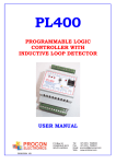
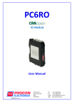
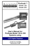
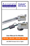
LD470
4 CHANNEL VEHICLE LOOP
DETECTORS
USER MANUAL
P O Box 24
Stanfield 3613
South Africa
Tel. +27-31-7028033
Fax +27-31-7028041
e-mail: [email protected]
web: www.proconel.com
30/01/2008V01
TABLE OF CONTENTS
1.
AN OVERVIEW OF THE LD470............................................................. 3
2.
LD470 HARDWARE ............................................................................... 5
2.1
2.2
2.3
2.4
2.5
SPECIFICATIONS ............................................................................... 5
WIRING – LD470 RELAY OUTPUTS ........................................................ 5
WIRING – LD470O OPTOCOUPLER OUTPUTS ........................................ 6
LOOP INSTALLATION GUIDE ............................................................ 7
LD470 FRONT PANEL ............................................................................. 8
3.
SWITCH SETTINGS ............................................................................... 9
4.
DIAGNOSTIC UNIT .............................................................................. 10
4.1
4.2
4.3
5.
USING THE DIAGNOSTIC UNIT. ................................................................ 10
CONFIGURING THE LD470..................................................................... 10
READING DATA FROM THE LD470. ......................................................... 11
DATA ADDESSES ............................................................................... 12
5.1 LD470 ( MODULE TYPE = 36) .......................................................... 13
5.2 LD470 REGISTER DESCRIPTION ............................................................ 15
5.2.1 Read/Write Digital I/O as a Register (40002) ............................... 15
5.2.2 Read/Write Mode (40102)............................................................ 15
5.2.3 Read/Write RS485 Module ID (40101)......................................... 16
5.2.4 Speed Measurement.................................................................... 16
5.2.5 Occupancy Measurement ............................................................ 16
2
1. AN OVERVIEW OF THE LD470
The LD470 is a high performance Eurocard 4 channel inductive loop detector designed for
use in traffic control applications, toll systems and vehicle counting.
The detector uses loop multiplexing to prevent crosstalk between adjacent loops and is easy
to set-up and install.
On power up or reset the detector performs an automatic tune procedure and is ready for use
within seconds.
The LD470 can operate as a standard 4 channel detector or may be configured for directional
logic where loops 1 and 2 and loops 3 and 4 work in pairs to give a direction output.
The LD470 can perform occupancy calculations and speed measurement.
Two communications ports are provided:
A Modbus RS232 communications port located on the front faceplate is used for configuration
and diagnostics with a notebook computer or with the LD470 handheld diagnostic unit.
A Modbus RS485 communications port on the connector at the rear of the unit can be used to
connect many detector units to a central computer or controller. Configuration and diagnostics
can also be accessed from this port.
The communications allows access to internal parameters such as loop input status, loop
fault status and counters, speed and occupancy.
The LD470 uses the latest ARM7 32bit processor for peak performance.
Standard features of the detector are :
•
Reset Switch.
The reset switch enables the detector to be manually reset during commissioning and
testing. This results in the detector re-tuning the sensing loop and becoming ready for
vehicle detection.
•
Presence / Passage feature.
Each channel can be individually setup to operate in presence or passage mode.
•
Selectable Presence Time.
Each channel can be individually setup for a presence time from seconds to hours.
•
Selectable Sensitivity.
Any combination of detect sensitivity level can be selected from 0.02% to 10.00%. The
undetect sensitivity level can also be programmed as required. An individual channel can
be switched off. This will prevent the fault output from being activated by unused loops.
•
Switch selectable Frequency.
Four frequency settings are available to prevent cross-talk between adjacent loops.
•
Network Layout.
The diagram below shows how the LD470 may be connected to a Modbus network. The
LD470 can be placed on the network with other I/O products such as the popular
PROMUX from Procon Electronics.
3
A typical application is where a PC (Personal Computer) is connected to the Network.
Many SCADA software packages support the MODBUS Master Protocol and can hence
retrieve data from the LD470 as well as Input Modules or send data to Output Modules.
The serial port of the PC is connected to an RS232/RS485 Converter which in turn is
connected to the Network.
PC
INPUTS
SERIAL
LINK
232/485
CONVERTER
8DI
MODBUS MASTER
MODBUS SLAVE
120 ohm Termination
8DO
OUTPUTS
LD470
4X LOOPS
LD470 MODULE SELECTION TABLE
MODEL
LD270
LD270O
LD470
LD470O
MODULE TYPE
2 Channel Eurocard Traffic Detector With Relays
2 Channel Eurocard Traffic Detector With OptoCoupler Outputs
4 Channel Eurocard Traffic Detector With Relays
4 Channel Eurocard Traffic Detector With OptoCoupler Outputs
4
2. LD470 HARDWARE
2.1 SPECIFICATIONS
1. Power Supply:
2. Microprocessor:
3. LD470 Relay Output:
4. LD470O Optocoupler Outputs:
5.
6.
7.
8.
9.
Indicators:
Sensitivity Range:
Inductance Tuning Range:
Response Time:
Failsafe:
fault
10. Frequency Range:
11. Protection:
12. Communications:
13.
14.
15.
16.
17.
18.
Communications Protocol:
Connector:
Dimensions:
Operating Temperature:
Storage Temperature:
Humidity:
19.6V - 28.8VDC.
32 bit ARM7 @ 50Mhz.
These outputs have a normally closed relay contact
rated at 0.5A/24VDC.
These outputs are normally open solid state
transistor outputs rated at 10mA/35VDC.
LED indicators show: Detect state and Loop Fault.
0.02% - 10.00%. (10.00 = Channel Disable)
15 - 1500 uH.
10ms – 65535ms ± 4ms.
1. The channel output will go into detect if a loop
is detected or the power fails.
2. The fault output will indicate a fault during a loop
fault or power fail.
Four step adjustable 15 – 130KHz.
Loop isolation transformer, zener diode and Gas
Arrestor protection on loop input.
1. RS232 - 19200, 8, n, 1 ID = 1.
2. RS485 – Baud (2400,4800,9600,19200,38400,
57600,115200).
Modbus RTU.
DIN 41612 Form C.
160mm X 100 X 25mm
-40°C to +80°C
-40°C to +85°C
up to 95% non condensing
2.2 WIRING – LD470 Relay outputs
TERMINAL FUNCTION
2a
4a
6a
8a
10a
12a
14a
16a
18a
20a
22a
24a
26a
28a
30a
32a
TERMINAL FUNCTION
CH3 Loop Input
CH3 Loop Input
No Connection
CH3 Output N/O
CH3 Output N/C
Earth
CH3 Output Common
CH2 Output N/O
CH2 Output Common
CH2 Output N/C
RS485 Comms +
RS485 Comms CH2 Loop Input
CH2 Loop Input
+24 VDC
0V
2c
4c
6c
8c
10c
12c
14c
16c
18c
20c
22c
24c
26c
28c
30c
32c
5
CH1 Loop Input
CH1 Loop Input
Fault Relay N/O
0V
RESET
Earth
CH4 Output N/O
CH1 Output N/O
CH1 Output Common
CH1 Output N/C
CH4 Output N/C
CH4 Output Common
CH4 Loop Input
CH4 Loop Input
+24 VDC
0V
2.3 WIRING – LD470O Optocoupler Outputs
TERMINAL FUNCTION
2a
4a
6a
8a
10a
12a
14a
16a
18a
20a
22a
24a
26a
28a
30a
32a
TERMINAL FUNCTION
CH3 Loop Input
CH3 Loop Input
CH3 Output +ve
Earth
CH3 Output -ve
CH2 Output +ve
CH2 Output -ve
RS485 Comms +
RS485 Comms CH2 Loop Input
CH2 Loop Input
+24 VDC
0V
2c
4c
6c
10c
12c
14c
18c
20c
22c
24c
26c
28c
30c
32c
CH1 Loop Input
CH1 Loop Input
Fault Output +ve
8c
0V
RESET
Earth
CH4 Output +ve
16c
CH1 Output +ve
CH1 Output -ve
CH4 Output -ve
CH4 Loop Input
CH4 Loop Input
+24 VDC
0V
The outputs are in the normal condition when the LD470 is powered, there is no vehicle on
the loop and there is no loop fault.
6
2.4 LOOP INSTALLATION GUIDE
1. The loop and feeder should be made from insulated copper wire with a minimum crosssectional area of 1.5mm2. The feeder should be twisted with at least 20 turns per metre.
Joints in the wire are not recommended and must be soldered and made waterproof.
Faulty joints could lead to incorrect operation of the detector. Feeders which may pick up
electrical noise should use screened cable, with the screen earthed at the detector.
2. The loop should be either square or rectangular in shape with a minimum distance of 1
metre between opposite sides. Normally 3 turns of wire are used in the loop. Large loops
with a circumference of greater than 10 metres should use 2 turns while small loops with a
circumference of less than 6 metres should use 4 turns. When two loops are used in close
proximity to each other it is recommended that 3 turns are used in one and 4 turns in the
other to prevent cross-talk.
3. Cross-talk is a term used to describe the interference between two adjacent loops. To
avoid incorrect operation of the detector, the loops on different detector units should be at
least 2 metres apart and on different frequency settings.
o
4. For loop installation, slots should be cut in the road using a masonry cutting tool. A 45 cut
should be made across the corners to prevent damage to the wire on the corners. The slot
should be about 4mm wide and 30mm to 50mm deep. Remember to extend the slot from
one of the corners to the road-side to accommodate the feeder.
5. Best results are obtained when a single length of wire is used with no joints. This may be
achieved by running the wire from the detector to the loop, around the loop for 3 turns and
then back to the detector. The feeder portion of the wire is then twisted. Remember that
twisting the feeder will shorten its length, so ensure a long enough feeder wire is used.
6. After the loop and feeder wires have been placed in the slot, the slot is filled with an epoxy
compound or bitumen filler.
7
2.5 LD470 Front Panel
Power LED
RS232
Rx/Tx
RS485 Rx
RS485 Tx
Channel
Fault LED
Channel
Detect LED
Reset
Switch
RS232
Communications
Port
8
3. SWITCH SETTINGS
ON
OFF
S1
S2
S1/S2
S1/S2
S2
S1
-
Frequency
S2
High
Med. High
Med. Low
Low
S1
Frequency
Switch
9
4. Diagnostic Unit
The LD470 diagnostic unit plugs into the RS232 communications port on the front panel of
the detector unit. The diagnostic unit gets power from the LD470 and is automatically
switched on when plugged into the LD470.
Scroll Up
Button
Scroll Down
Button
4.1 Using the diagnostic unit.
The up and down scroll buttons are used to scroll through the menu items.
To edit a value you must perform the following sequence:
1. Push both buttons at the same time. The least significant digit will start flashing to
indicate the unit is in edit mode. If the digit does not flash then either the buttons were
not pushed together or the data cannot be edited because it is read only.
2. Use the scroll down button to increment the value of the digit.
3. Use the scroll up button to advance to the next digit.
4. When the correct value has been entered, push both of the buttons together to enter
and save the value. If the entered value changes to another value different from the
value entered, this means that the entered value was out of range and has been
undated with a default value.
4.2 Configuring the LD470.
The following sections describe the data that can be configured or read by the diagnostic unit.
1.
2.
3.
4.
5.
6.
7.
8.
9.
10.
11.
12.
13.
14.
15.
16.
Ch1 Sensitivity: 0.02% to 10.00% where 10.00% = Channel Disabled.
Ch2 Sensitivity: 0.02% to 10.00% where 10.00% = Channel Disabled.
Ch3 Sensitivity: 0.02% to 10.00% where 10.00% = Channel Disabled.
Ch4 Sensitivity: 0.02% to 10.00% where 10.00% = Channel Disabled.
Ch1 Undetect Sensitivity: 0.01% to 9.99%. Cannot be larger than Sensitivity.
Ch2 Undetect Sensitivity: 0.01% to 9.99%. Cannot be larger than Sensitivity.
Ch3 Undetect Sensitivity: 0.01% to 9.99%. Cannot be larger than Sensitivity.
Ch4 Undetect Sensitivity: 0.01% to 9.99%. Cannot be larger than Sensitivity.
Ch1 On Filter (Delay): 10ms to 65535ms.
Ch2 On Filter (Delay): 10ms to 65535ms.
Ch3 On Filter (Delay): 10ms to 65535ms.
Ch4 On Filter (Delay): 10ms to 65535ms.
Ch1 Extend: 4ms to 65535ms.
Ch2 Extend: 4ms to 65535ms.
Ch3 Extend: 4ms to 65535ms.
Ch4 Extend: 4ms to 65535ms.
10
17.
18.
19.
20.
21.
22.
23.
24.
25.
26.
27.
28.
29.
30.
31.
32.
33.
34.
35.
36.
Ch1 Presence time: 2min to 65535min.
Ch2 Presence time: 2min to 65535min.
Ch3 Presence time: 2min to 65535min.
Ch4 Presence time: 2min to 65535min.
Ch1 Pulse time: 100ms to 65535ms.
Ch2 Pulse time: 100ms to 65535ms.
Ch3 Pulse time: 100ms to 65535ms.
Ch4 Pulse time: 100ms to 65535ms.
Ch1 Mode: 0 = presence, 1 = pulse.
Ch2 Mode: 0 = presence, 1 = pulse.
Ch3 Mode: 0 = presence, 1 = pulse.
Ch4 Mode: 0 = presence, 1 = pulse.
RS485 Stop Bits: 1 or 2.
RS485 Parity: 0 = none, 1 = even, 2 = odd.
RS485 Baud Rate: 2400, 4800, 9600, 19200, 38400, 57600, 11520.
Occupancy Time: 1sec to 65535sec.
Loop Spacing: For speed measurement. 0.1m to 10.0m
Direction Logic Pulse Time: 1ms to 65535ms.
LD470 Mode: 0 = Normal. +1 change to direction logic. +2 modbus operates relays.
RS485 Node ID: Address 0 to 253.
4.3 Reading data from the LD470.
The following registers give information relating to the channels.
1.
2.
3.
4.
5.
6.
7.
8.
9.
10.
11.
12.
13.
14.
15.
16.
17.
18.
Ch1 DL/L: The actual change in loop inductance as a vehicle moves over loop 1.
Ch2 DL/L: The actual change in loop inductance as a vehicle moves over loop 2.
Ch3 DL/L: The actual change in loop inductance as a vehicle moves over loop 3.
Ch4 DL/L: The actual change in loop inductance as a vehicle moves over loop 4.
Ch1 Frequency: The frequency of the loop1 will change as the inductance changes.
Ch2 Frequency: The frequency of the loop2 will change as the inductance changes.
Ch3 Frequency: The frequency of the loop3 will change as the inductance changes.
Ch4 Frequency: The frequency of the loop4 will change as the inductance changes.
Ch1 Counter: 0 to 4294967295 (32 bit).
Ch2 Counter: 0 to 4294967295 (32 bit).
Ch3 Counter: 0 to 4294967295 (32 bit).
Ch4 Counter: 0 to 4294967295 (32 bit).
Ch1 Occupation: The amount of time loop 1 was occupied %.
Ch2 Occupation: The amount of time loop 2 was occupied %.
Ch3 Occupation: The amount of time loop 3 was occupied %.
Ch4 Occupation: The amount of time loop 4 was occupied %.
Speed 1&2: The speed of the last vehicle that traveled from loop1 to loop2.
Speed 3&4: The speed of the last vehicle that traveled from loop3 to loop4.
11
5. DATA ADDESSES
The data in the module is stored in registers. These registers are accessed over the network
using the MODBUS communication protocol.
The MODBUS mode used is the RTU mode with the following RS232 set-up:
BAUD RATE
DATA BITS
PARITY
STOP BITS
19200
8
NONE
1
Note: Due to the limited buffer memory size in the LD470, the Modbus message length must
be limited to 100 consecutive read or write registers.
There are 4 types of variables which can be accessed from the module. The LD470 module
has one or more of these data variables.
Type
Start Address
Variable
1
2
3
4
00001
10001
30001
40001
Digital Outputs
Digital Inputs
Input registers (Analog/Counters)
Output registers (Analog/Counters)
12
5.1 LD470
Modbus
Address
10001
10002
10003
10004
10005
10006
10007
10008
00009
00010
00011
00012
30001
40002
30011
30012
30013
40014
40015
30016
30021
30022
30023
40024
40025
30026
30031
30032
( MODULE TYPE = 36)
Register Name
Low
Limit
0
0
0
0
0
0
0
0
0
0
0
0
High
Limit
1
1
1
1
1
1
1
1
1
1
1
1
Access
N/A
N/A
R
N/A
N/A
R/W
CH1 DL/L
CH1 Frequency
MSB
CH1 Frequency
LSB
CH1 Counter
MSB
CH1 Counter
LSB
CH1 Occupation
-1000
15000
+1000
125000
R
R
“
“
R
0
65535
R/W
0
65535
R/W
0
100
R
CH2 DL/L
CH2 Frequency
MSB
CH2 Frequency
LSB
CH2 Counter
MSB
CH2 Counter
LSB
CH2 Occupation
-1000
15000
+1000
125000
R
R
“
“
R
0
65535
R/W
0
65535
R/W
0
100
R
CH3 DL/L
CH3 Frequency
MSB
-1000
15000
+1000
125000
R
R
Loop1 Fault
Loop1 Output
Loop2 Fault
Loop2 Output
Loop3 Fault
Loop3 Output
Loop4 Fault
Loop4 Output
Relay 1 Output
Relay 2 Output
Relay 3 Output
Relay 4 Output
S/W Version /
Module Type
Digital I/O
R
R
R
R
R
R
R
R
R/W
R/W
R/W
R/W
13
Comments
Read Loop 1 Fault Status
Read Loop 1 Detect Status
Read Loop 2 Fault Status
Read Loop 2 Detect Status
Read Loop 3 Fault Status
Read Loop 3 Detect Status
Read Loop 4 Fault Status
Read Loop 4 Detect Status
Write/Read Relay 1 Output
Write/Read Relay 2 Output
Write/Read Relay 3 Output
Write/Read Relay 4 Output
High Byte = Software Version
Low Byte = 36
Digital Outputs in lower 8 bits. 8 - 1.
Relays in upper bits. 12 - 9.
Change in Loop inductance X 0.01%
Loop Frequency. MSB and LSB combine to give
a 32 bit value X 0.001 KHz.
"
Counter MSB and LSB combine to give a 32 bit
Value.
Counter with range 0 to 4294967295.
Write to clear or preset.
Loop Occupation Time %
Change in Loop inductance X 0.01%
Loop Frequency. MSB and LSB combine to give
a 32 bit value X 0.001 KHz.
"
Counter MSB and LSB combine to give a 32 bit
Value.
Counter with range 0 to 4294967295.
Write to clear or preset.
Loop Occupation Time %
Change in Loop inductance X 0.01%
Loop Frequency. MSB and LSB combine to give
a 32 bit value X 0.001 KHz.
30033
40034
40035
30036
30041
30042
CH3 Frequency
LSB
CH3 Counter
MSB
CH3 Counter
LSB
CH3 Occupation
“
“
R
"
0
65535
R/W
0
65535
R/W
0
100
R
-1000
15000
+1000
125000
R
R
“
“
R
0
65535
R/W
0
65535
R/W
0
100
R
Counter MSB and LSB combine to give a 32 bit
Value.
Counter with range 0 to 4294967295.
Write to clear or preset.
Loop Occupation Time %
Counter MSB and LSB combine to give a 32 bit
Value.
Counter with range 0 to 4294967295.
Write to clear or preset.
Loop Occupation Time %
30046
CH4 DL/L
CH4 Frequency
MSB
CH4 Frequency
LSB
CH4 Counter
MSB
CH4 Counter
LSB
CH4 Occupation
30051
30052
Speed 1&2
Speed 3&4
0
0
65535
65535
R
R
Speed calculated from loop1 & 2 (Km/hr)
Speed calculated from loop3 & 4 (Km/hr)
40101
40102
40103
RS485 Node ID
Detector Mode
Direction Logic
Pulse Duration
Loop Spacing
0
0
0
253
3
65535
R/W
R/W
R/W
Read/Write Module ID (DEFAULT = 254)
Read/Write Mode
milliseconds
0
255
R/W
Occupancy
Period
RS485 Baud
Rate
RS485 Parity
RS485 Stop Bits
0
65535
R/W
Distance between leading edge of loops for
speed measurement. Eg: 20 = 2.0 metres
Occupancy sample period in seconds
2400
11520
R/W
2400, 4800, 9600, 19200, 38400,57600,115200
0
1
2
2
R/W
R/W
0 = none, 1 = even, 2 = odd
1 = 1 stop bit, 2 = 2 stop bits
2
255
R/W
Detector sensitivity X 0.01% DL/L
1
255
R/W
Detector undetect sensitivity X 0.01% DL/L
10
10
1
65535
65535
65535
R/W
R/W
R/W
Detect Time X 0.001 seconds
UnDetect Time X 0.001 seconds
Presence time in seconds.
10
0
65535
1
R/W
R/W
Pulse duration X 0.001 seconds
0 = presence, 1 = pulse
2
255
R/W
Detector sensitivity X 0.01% DL/L
1
255
R/W
Detector undetect sensitivity X 0.01% DL/L
10
65535
R/W
Detect Time X 0.001 seconds
30043
40044
40045
40104
40105
40121
40122
40123
40131
40132
40133
40134
40135
40136
40137
40141
40142
40143
CH1 detect
Sensitivity
CH1 undetect
Sensitivity
CH1 On Filter
CH1 Extend
CH1 Presence
Time
CH1 Pulse Time
CH1 Mode
CH2 detect
Sensitivity
CH2 undetect
Sensitivity
CH2 On Filter
14
Change in Loop inductance X 0.01%
Loop Frequency. MSB and LSB combine to give
a 32 bit value X 0.001 KHz.
"
40144
40145
40146
40147
40151
40152
40153
40154
40155
40156
40157
40161
40162
40163
40164
40165
40166
40167
CH2 Extend
CH2 Presence
Time
CH2 Pulse Time
CH2 Mode
CH3 detect
Sensitivity
CH3 undetect
Sensitivity
CH3 On Filter
CH3 Extend
CH3 Presence
Time
CH3 Pulse Time
CH3 Mode
CH4 detect
Sensitivity
CH4 undetect
Sensitivity
CH4 On Filter
CH4 Extend
CH4 Presence
Time
CH4 Pulse Time
CH4 Mode
10
1
65535
65535
R/W
R/W
UnDetect Time X 0.001 seconds
Presence time in seconds.
10
0
65535
1
R/W
R/W
Pulse duration X 0.001 seconds
0 = presence, 1 = pulse
2
255
R/W
Detector sensitivity X 0.01% DL/L
1
255
R/W
Detector undetect sensitivity X 0.01% DL/L
10
10
1
65535
65535
65535
R/W
R/W
R/W
Detect Time X 0.001 seconds
UnDetect Time X 0.001 seconds
Presence time in seconds.
10
0
65535
1
R/W
R/W
Pulse duration X 0.001 seconds
0 = presence, 1 = pulse
2
255
R/W
Detector sensitivity X 0.01% DL/L
1
255
R/W
Detector undetect sensitivity X 0.01% DL/L
10
10
1
65535
65535
65535
R/W
R/W
R/W
Detect Time X 0.001 seconds
UnDetect Time X 0.001 seconds
Presence time in seconds.
10
0
65535
1
R/W
R/W
Pulse duration X 0.001 seconds
0 = presence, 1 = pulse
5.2 LD470 Register Description
5.2.1 Read/Write Digital I/O as a Register (40002)
Address
40002
Bit 7
Det 4
Bit 6
Fault 4
Bit 5
Det 3
Bit 4
Fault 3
Bit 3
Det 2
Bit 2
Fault 2
Bit 1
Det 1
Bit 0
Fault 1
Address
40002
Bit 15
-
Bit 14
-
Bit 13
-
Bit 12
-
Bit 11
RLY 4
Bit 10
RLY 3
Bit 9
RLY 2
Bit 8
RLY 1
5.2.2 Read/Write Mode (40102)
MODE NUMBER
0
1
2
3
LD470 Operation Mode
Detector Mode
Direction Logic
Detector Mode
Direction Logic
15
Relay Operation
Detector operates relays
Detector operates relays
Relays operated via Modbus
Relays operated via Modbus
In the detector mode the LD470 works as a 4 channel detector. Each counter is connected to
a detector output and counts up as a vehicle passes over the loop. If the relays are connected
to the detector (mode 0) then the relay will give a presence output when a vehicle is on the
loop.
In direction logic mode the LD470 uses counter 1 as an up/down counter for loops 1 and 2.
Counter 2 is an up/down counter for loops 3 and 4. If the relays are connected to the detector
(mode 1) then a pulse output will correspond to a vehicle going over the loop pair.
When the Relays are connected to the Modbus register (Mode 2 and Mode 3) they are
switched on and off by writing to the corresponding Modbus address.
5.2.3 Read/Write RS485 Module ID (40101)
The LD470 will always respond to the default address 254. The LD470 will also respond to an
address as programmed into register 40101.
5.2.4 Speed Measurement
The LD470 uses loop 1 and loop 2 as a pair for speed measurement. It also uses loop 3 and
loop 4 as a second pair for speed measurement. The loops must be positioned so that the
vehicle passes over loop 1 before loop 2. The speed is calculated from the distance between
the leading edges of the loops, and the measured time taken for the vehicle to get from loop 1
to loop 2.
The Modbus register 40104 is used to enter the distance between the leading edges of the
loops. This value is entered in 0.1 metre for example, if the leading edges of the two loops are
2.3 metres apart, then the value 23 must be entered into this register. The greater the
distance between the loops, the less the error.
5.2.5 Occupancy Measurement
The occupancy is the length of time that a vehicle is over the loop. The occupancy is
calculated over a sample period and is entered into Modbus register 40105. The units are
seconds. A typical value would be 30, which means that the occupancy is sampled over a 30
second period. The occupancy is calculated as a % of the sample period. For example, if
vehicles were over the loop for 15 seconds in a 30 second sample period, then the
occupancy would be 50%.
16