1
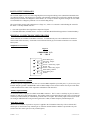
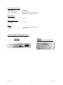
TCS100
INTELLIGENT TIME CODE SWITCHER
Masterclock, Inc.
2484 W Clay Street St. Charles, MO 63301
Tel: 636-724-3666 Fax: 636-724-3776
www.masterclock.com
TABLE OF CONTENTS
DISCLAIMER .................................................................................................................................................2
INTRODUCTION ...........................................................................................................................................3
GETTING STARTED .....................................................................................................................................3
Select Desired Setup Parameters .......................................................................................................3
Connect Time Code Sources .............................................................................................................3
Connect RS-232 Terminal (Optional) ...............................................................................................3
Connect Output To Time Code Bus ..................................................................................................4
Connect a Power Source ...................................................................................................................4
INITIAL OPERATION ...................................................................................................................................4
FRONT-PANEL BUTTON OPERATION .....................................................................................................4
LED BEHAVIOR ............................................................................................................................................4
Source 1 / Source 2 ...........................................................................................................................4
TIME CODE ANALYSIS CRITERIA ...........................................................................................................5
Signal Validity ..................................................................................................................................5
Time/Date Validity ............................................................................................................................5
GPS Lock Validity ............................................................................................................................5
Requirements For Time Code Sources ............................................................................................................5
Time Code Types ..............................................................................................................................5
Signal Levels .....................................................................................................................................6
Fault-Tolerant Considerations ...........................................................................................................6
Configuring TCS100 Optional Settings ..........................................................................................................6
Access to PC Board ...........................................................................................................................6
DIP Switch Configuration .................................................................................................................6
Relay Closure Alarm Sensitivity ............................................................................. 6
Audible Alarm Sensitivity ....................................................................................... 6
Time/Date Analysis ................................................................................................ 7
GPS Signal Analysis .............................................................................................. 7
RS-232 Output Messages ................................................................................................................................8
PHYSICAL CONNECTIONS/CONFIGURATION.......................................................................................8
Simplified I/O Connections ...............................................................................................................8
Figure 2 .............................................................................................................................................8
IBM 9 Pin Serial Port Compatible ....................................................................................................8
Auxiliary Signal Switching ...............................................................................................................8
Alarm Relay Closure .........................................................................................................................8
PROBLEMS - TROUBLESHOOTING ..........................................................................................................9
HARDWARE ..................................................................................................................................................9
Operating Environment .....................................................................................................................9
Time Code & Alarm Relay Contact Closure .....................................................................................9
Battery Operation ..............................................................................................................................9
SPECIFICATIONS .........................................................................................................................................9
Time Code Inputs ..............................................................................................................................9
Time Code Output .............................................................................................................................9
Serial Communications .....................................................................................................................9
Power Supply Requirements ...........................................................................................................10
Lithium Battery ...............................................................................................................................10
Operating Temperature ...................................................................................................................10
Physical ...........................................................................................................................................10
OPTIONS & Related hardware .....................................................................................................................10
LIMITED WARRANTY..............................................................................................................................11
Exclusions .......................................................................................................................................11
Warranty Limitations ......................................................................................................................11
Exclusive Remedies ........................................................................................................................11
Hardware Service ..........................................................................................................................................11
TCS100 -
Oct -04
1
(C) Masterclock, Inc.
DISCLAIMER
The information contained in this document is subject to change without notice.
Masterclock, Inc. (hereinafter MC) makes no warranty of any kind with regard to this material, including, but
not limited to, the implied warranties of merchantability and fitness for a particular purpose.
MC shall not be liable for errors contained herein or for incidental or consequential damages in connection with
the furnishing, performance, or use of this material.
See limited warranty information at the end of this document.
TCS100 -
Oct -04
2
(C) Masterclock, Inc.
INTRODUCTION
The TCS100 is an intelligent time code signal switching module enhancing fault-tolerant support for critical
operations requiring time code.
Features include:
• Support for switching of SMPTE, IRIG-B time code formats
• Auto-detects time code type/information
• Auxiliary signal routing
• Configurable audible alarm
• Configurable relay contact closure alarm
• Advanced analysis of time code time and date data
• RS-232 serial event output for logging
GETTING STARTED
Setup for initial operation consists of:
• selecting the desired setup parameters with switches inside the case
• supplying two sources of equivalent time code
• connecting RS-232 output to terminal or logging device
• connecting the output to your time code bus
• connecting a power source
Select Desired Setup Parameters
The factory default/setup of the TCS100 configuration DIP switches (located on the PCB inside the case) will be
suitable for most switching applications. However, now is the best time to review the configuration options to decide
if some need to be changed. The TCS100 is configured at the factory to provide both relay closure and audible
alarms only when an auto-switching failure has occurred (a dual-source failure). Time/date analysis is not enabled.
Time/date analysis should be enabled in scenarios where an unexpected/undesired jump in encoded time/date
information could occur from one of the time code sources.
Audible and relay closure alarms can be configured independently to “fire” when a single source fails as opposed to
both. Users desiring immediate notification of any operational anomaly may re-configure these alarm settings.
See the section entitled Configuring TCS100 Optional Settings for more information on these features.
Connect Time Code Sources
Connect the time code output (unbalanced) from your primary time code source to the source 1 BNC
input on the TCS100 rear panel. Connect another operating time code source (secondary or backup) to the source 2
BNC input.
See the section entitled Requirements for Time Code Sources for more information on what types of time codes can
and should be used as inputs to the TCS100.
Connect RS-232 Terminal (Optional)
Connect the serial output of the Auxiliary (DB-9) connector on the rear panel of the TCS100 to an RS-232 terminal
device for diagnostic and event information capture, including diagnosing problems during installation. Useful for
logging both manual and automatic events occurring on the TCS100. The auxiliary connector may be attached
directly to a PC serial port using a null-modem serial cable. Connection to other devices, or in situations involving
usage of multiple auxiliary connector features, may require design of a custom cable. See the section entitled
TCS100 DB-9 Pinout for connection specification.
TCS100 -
Oct -04
3
(C) Masterclock, Inc.
The TCS100 transmits at 9600 baud, 8 data bits, 1 stop bit, with no parity. See the section entitled RS-232 Event
Output for more information on TCS100 transmitted messages.
Connect Output To Time Code Bus
The output BNC connector on the rear panel of the TCS100 is the relay-switched source 1/source 2 signal output.
Attach the output connector to your time code “bus”. This signal can then be daisy-chained, split, or amplified as
necessary to drive time code reading devices in your facility which are to benefit from the fault-tolerant switching of
the TCS100 unit.
The TCS100 does not amplify or alter in any way the signal characteristics of a time code source. The signal
characteristics of the output connector are identical to the time code generating device connected to its switched
source.
Connect a Power Source
The TCS100 accepts 9-28 volts DC power. A wall mount-style power supply is provided. International power
supplies are available from the factory. Contact sales for additional information.
Upon application of power to the TCS100 the unit will flash all six front-panel LEDs twice indicating normal startup.
INITIAL OPERATION
The TCS100 initializes with auto-switching mode enabled and source 1 selected (switched) to output. The unit will
immediately enter into an identification process whereby the characteristics of time code applied to sources 1 and 2
are identified. Sources 1 and 2 will indicate a failure state until the TCS100 has completely identified the time code
on the given source. This process can take up to three minutes. Thereafter, the TCS100 will remember the last type
of time code used and power-up initialization will complete much more quickly.
FRONT-PANEL BUTTON OPERATION
TCS100 control buttons are located on the front-panel of the unit.
Pressing the AUTO button in the center of the panel enables auto-switching mode.
Pressing the SOURCE 1 button (left-hand side of the panel) manually switches the output to the source 1 input
regardless of the status of time code on that source. Pressing the SOURCE 2 button (right-hand side of the panel)
manually switches the output to the source 2 input, again, regardless of the status of time code on that source.
Note: Manually selecting either SOURCE 1 or SOURCE 2 disengages auto-switching mode. To re-engage autoswitching mode press the AUTO button.
LED BEHAVIOR
Source 1 / Source 2
SELECT
* When slowly blinking - indicates that the given source is selected (switched) to output when autoswitching mode is enabled.
* When steady lit – indicates that the given source is selected (switched) to output manually (auto-switching
mode is not enabled).
* When unlit – indicates that the source is not selected (switched).
FAIL
TCS100 -
* When steady lit – indicates that the time code on that source is deemed invalid per any of several
evaluation criteria.
* When unlit – indicates that the time code on that source is considered valid per all of the enabled
evaluation criteria.
Oct -04
4
(C) Masterclock, Inc.
Auto
SELECT
* When steady lit – indicates that auto-switching mode is enabled.
* When unlit – indicates that auto-switching mode is not enabled (source 1 or 2 has been manually selected).
FAIL
* When steady lit – indicates that auto-switching mode has failed because time code on both sources 1 and 2 has
been deemed invalid per any of several evaluation criteria. This mode will be accompanied by failure
indications for source 1 and 2.
TIME CODE ANALYSIS CRITERIA
The TCS100 time code decoder samples several frames of time code on source 1 and 2 inputs and performs two
layers of analysis to determine if the source is valid. If one or more of the criteria detailed below fail, the source will
be considered invalid (failed). When the condition causing the failure is corrected the TCS100 will clear any
activated alarms and resume normal operation without user intervention.
Signal Validity
TCS100 decoders examine the time code signal to detect several possible problems, including but not limited to:
• total signal loss resulting from time code generator failure, faulty cabling, etc.
• signal corruption resulting from electrical interference
• signal corruption resulting from failure in time code generator
Time/Date Validity
Encoded on-time reference markers, time, and date (when available) are analyzed by the TCS100 when this option is
enabled. If an error exceeding 100 milliseconds is detected between source 1 and 2 a third arbitration source (an
internal real-time clock) will be used to determine which source has experienced the erroneous time jump.
Note: The time/date analysis feature cannot be used to identify time code source(s) which are slowly drifting away
from an accurate reference.
GPS Lock Validity
The Masterclock, Inc. GPS-200 series master clock time code generators encode a status bit into the SMPTE and
IRIG-B time code signals to indicate when the receiver has a GPS satellite lock that is valid for critical timing.
When you specify through dip switch configuration that a time code generator connected to source 1 or 2 is a GPS
this special bit will be used as an additional criteria is to judge source validity. In auto-switching mode, the switcher
will remain switched to the GPS source when satellite fix is available.
REQUIREMENTS FOR TIME CODE SOURCES
Time Code Types
The TCS100 can accept any of the following time code types:
•
•
SMPTE 30fps (NTSC and drop-frame), 25fps (EBU/PAL), and 24fps (Film)
IRIG-B & B(1)
You must apply the same type of time code to source 1 and 2 inputs.
TCS100 -
Oct -04
5
(C) Masterclock, Inc.
Signal Levels
The TCS100 can decode time code levels between 1- 15Vpp. Time code signal levels at source 1 and 2 inputs
should not have more than a 5% relative differential.
Fault-Tolerant Considerations
Fault-tolerant considerations dictate that both TCS100 source inputs should receive time code from equivalent
generator devices with equivalent configurations. If one source encodes time zone offsets or date information the
other must do the same. Physical time code signal characteristics should be near-identical where possible. Deviation
from this prescribed setup could have adverse effects on time code decoding devices when switching occurs, and
may defeat the purpose of a fault-tolerant time code source.
CONFIGURING TCS100 OPTIONAL SETTINGS
Access to PC Board
In order to gain access to the setup switches it is necessary to remove the case from the TCS100 as follows:
First disconnect the power and other cables from the unit. Even though the highest voltage inside the TCS100 is 12
VDC (which is generally not dangerous to touch), accidentally shorting a trace or wire inside the unit with power on
could destroy or damage any one of the extremely sensitive electronic components. Accidentally shorting a wire or
trace or subjecting the unit to a static discharge, even for a very small fraction of a second, can destroy these
components. Such damage is not covered by the warranty.
Remove the two Phillips screws on the rear panel (this is the end with the power socket, three BNC connectors, and a
DB-9 connector). Holding the case of the unit in one hand, slide the rear panel assembly outward from the rear. The
entire rear panel assembly and PC board will slide out.
As was mentioned above, the PC board is sensitive to any electrical signal including static discharge. Do not touch
the PC board with any external wiring and, whenever possible, handle the unit by the rear panel or on the edge of the
PC board as you would a Compact Disc. When not changing the switches, always keep the PC board installed in the
case.
When reassembling the unit take care that the PC board is properly fitted into the slots in the base of the chassis.
When properly inserted, the PC board and rear panel assembly will slide easily into the case, no force is necessary.
The front-panel LEDs and buttons will protrude through their designed holes without force. The warranty does not
cover damage caused to the unit while removing or reassembling the PC board.
DIP Switch Configuration
DIP switch bank S1 located on the PCB configures optional settings for the TCS100.
Relay Closure Alarm Sensitivity
By default, the alarm relay will close only when the TCS100 is in auto-switching mode and has detected a failure
condition on both time code sources. The relay can be configured to close when any source fails during autoswitching mode.
Switch S1-3 configures the relay closure alarm sensitivity setting per the following table:
Function
S1-3
Source 1 AND 2 failure alarms
Source 1 OR 2 failure alarms
OFF (default)
ON
Audible Alarm Sensitivity
TCS100 -
Oct -04
6
(C) Masterclock, Inc.
By default, the audible alarm will activate only when the TCS100 is in auto-switching mode and has detected a
failure condition on both time code sources. The audible alarm can be configured to activate when any source fails
during auto-switching mode.
Switch S1-4 configures the audible alarm activation sensitivity setting per the following table:
Function
S1-4
Source 1 AND 2 failure alarms
Source 1 OR 2 failure alarms
OFF (default)
ON
The audible alarm also has a volume control feature configured from J4 pin jumper (located in the upper left-hand
corner of the PCB.) The volume is configured per the following table:
Function
Jum
Softer audible alarm
Louder audible alarm
No audible alarm
per Position
pin jumper on pins 1-2 (default)
pin jumper on pins 2-3
pin jumper removed
(hang pin jumper off of pin 2 only)
Time/Date Analysis
Time/Date analysis is an advanced function which looks at the on-time reference mark of the time code signal as well
as the time/date information encoded therein. The TCS100 will combine measurements of this data and look for a
real-time differential between source 1 and 2. If a differential of greater than 100 milliseconds is detected the
TCS100 will assume that that either source 1 or source 2 has incorrect time. To determine which source is invalid,
the internal real-time clock will be used as a third arbitration/voting source. During normal valid operation the realtime clock is refreshed from time code and therefore does not incur drift on its own.
Time/Date analysis is not enabled by default. This function will only be useful and work correctly when precisionreferenced master clocks or equivalent time code generator devices are attached to the TCS100’s source inputs. The
time/date analysis feature cannot be used to detect a slowly drifting time code source.
Switch S1-5 configures the time/date analysis feature per the following table:
Function
SW
Time/Date Analysis disabled
Time/Date Analysis enabled
1-5
OFF (default)
ON
GPS Signal Analysis
If a Masterclock, Inc. GPS-200 series master clock is connected to source 1 and/or source 2 you can configure the
switcher to apply an additional signal validity criteria utilizing a special bit encoded by the GPS-200 into the time
code signals. This bit indicates whether or not the GPS-200 has a GPS satellite fix that is valid for critical timing.
Switch S1-6 on configures the switcher for a GPS-200 on source 1, and applies the GPS fix validity criteria.
Switch S1-7 on configures the switches for a GPS-200 on source 2, and applies the GPS fix validity criteria.
If you do not wish to apply the extra GPS validity criteria to switching do not enable S1-6 or S1-7 functionality.
Never enable S1-6 or S1-7 when a time code source other than a GPS-200 series master clock is connected to the
respective source. Doing so will cause unpredicatable and erroneous behavior.
All other switch positions are reserved for future use an should remain in the factory default positions (OFF).
TCS100 -
Oct -04
7
(C) Masterclock, Inc.
RS-232 OUTPUT MESSAGES
The TCS100 outputs a series of verbose English plain-text messages describing events (manual and automatic) that
occur during operation. The messages are generally self-explanitory and describe events such as manual front-panel
button presses, automatic switching due to source failure, etc. It may be useful to log these messages on a PC or RS232 terminal device to diagnose problems or to record switching activity.
The source failure message will contain the text “(flags=xx)”, where xx is a numeric code indicating the reason for
the failure. Currently defined codes are:
1 – time code signal failure (loss/significant corruption of signal)
2 – time/data data failure (encoded source 1 or source 2 time/date data differential stepped out of 100ms boundary)
PHYSICAL CONNECTIONS/CONFIGURATION
All I/O functions are available on the DB-9 at all times. To simultaneously use some combination of functions a
custom cable will be necessary. Such cables can be fabricated locally by an electronic technician or on a custom
basis by MC.
Simplified I/O Connections
Figure 2
SIMPLIFIED I/O
P1 - DB-9
1
6
2
7
3
8
4
9
5
Alarm Relay N/C
Auxiliary Output
RS-232 In
Source 1 Auxiliary Input
RS-232 Out
Source 2 Auxiliary Input
Alarm Relay Common
Alarm Relay N/O
Ground
IBM 9 Pin Serial Port Compatible
The RS-232 pin out configuration is the same as is used on IBM compatible 9 pin serial ports, i.e. pin 2 receive, pin 3
transmit and pin 5 ground. A standard DB-9 male to DB-25 adapter can be used to connect most 25 pin serial cables.
A null-modem interface cable will be required to communicate with most PC’s.
Auxiliary Signal Switching
An switched auxiliary input pair is available on the DB-9 connector. Pin 7 is source 1 auxiliary in, pin 8 is source 2
auxiliary in, and pin 6 is the switched output. The auxiliary inputs correspond to the time code source 1/2 inputs and
will always switch (manually or automatically) with the source 1/2 inputs. The auxiliary input switch may be useful
for routing an additional time code generator signal such as a PPS, 5/10mHz frequency standard output, etc.
Alarm Relay Closure
When no alarm condition is present or no power is applied to the TCS100 the alarm relay will rest with the N/C
contact (pin 1) connected to relay common (pin 4). When an uncleared alarm condition is present the relay will
switch to the N/O contact (pin 9) to relay common (pin 4).
TCS100 -
Oct -04
8
(C) Masterclock, Inc.
PROBLEMS - TROUBLESHOOTING
All TCS100 units are checked for proper operation before shipment and unless physical damage is found, the unit is
probably functional.
If you have problems getting the unit to work:
• double check all input and output connections
• make sure that power is applied and the front panel LEDs are showing the startup sequence when first activated
• verify that a valid time code is connected to both source 1 and 2 inputs
• verify that the time code input level is in range
If the unit does not work even after the above precautions have been noted contact the factory.
HARDWARE
Operating Environment
The TCS100 is not water or moisture proof. Treat it as you would any other delicate electronic device and do not
expose it to water, moisture, excessive heat or physical abuse.
Time Code & Alarm Relay Contact Closure
The absolute maximum contact rating is .5 Amp at 24 VDC. Nominal current should not exceed 200 ma.
Connecting high current loads and exceeding the recommended rating could damage the relay and traces on the PC
board. Such damage is not covered by warranty.
Battery Operation
If desired the unit can be operated from a 12 VDC power source (9-28 VDC range). Observe voltage polarity printed
on the rear panel.
SPECIFICATIONS
Time Code Inputs
Format ......................................... selectable (auto-detected)
Level ........................................... 1Vpp – 15Vpp, +/-5% source-relative differential
Impedance ................................... > 100K ohm
Connectors .................................. BNC female
Time Code Output
Format ......................................... same as selected source
Level ........................................... same as selected source
Impedance ................................... same as selected source
Connector .................................... BNC female
Serial Communications
Baud Rate .................................... 9600
Data Bits ..................................... 8
Stop Bits ...................................... 1
Parity ........................................... None
TCS100 -
Oct -04
9
(C) Masterclock, Inc.
Power Supply Requirements
Input voltage ............................... 9-28 VDC
Input power connector ................ 2mm male plug
Power consumption ..................... audible alarm activated 120mA (1 watt)
.................................................... audible alarm silent 50mA (500mW)
Lithium Battery
Estimated lifetime ....................... 10 years
Operating Temperature
Temperature ................................ 0 to +70 °C
Physical
Size.............................................. 1.5 x 4.1 x 5.5 in. (3.8 x 10.4 x 14 cm)
Weight ......................................... 17 oz. (480 gr.)
OPTIONS & RELATED HARDWARE
Rack Mount
TCS100 -
Oct -04
GPS-200
Master Clock /Time Code Generator
10
(C) Masterclock, Inc.
LIMITED WARRANTY
This Masterclock, Inc. (hereinafter MC) product warranty extends to the original purchaser.
MC warrants the TCS100 against defects in materials and workmanship for a period of five years from date of sale. If
MC receives notice of such defects during the warranty period, MC will, at its option, either repair or replace
products which prove to be defective.
Should MC be unable to repair or replace the product within a reasonable amount of time, the customer's alternate
remedy shall be a refund of the purchase price upon return of the product to MC. This warranty gives the customer
specific legal rights. Other rights, which vary from state to state or province to province, may be available.
Exclusions
The above warranty shall not apply to defects resulting from improper or inadequate maintenance by the customer,
customer-supplied software or interfacing, unauthorized modification or misuse, operation outside of the
environmental specifications for the product or improper site preparation and maintenance (if applicable).
Warranty Limitations
MC MAKES NO OTHER WARRANTY, EITHER EXPRESSED OR IMPLIED, WITH RESPECT TO THIS
PRODUCT. MC SPECIFICALLY DISCLAIMS THE IMPLIED WARRANTIES OF MERCHANTABILITY OR
FITNESS FOR A PARTICULAR PURPOSE.
In any state or province which does not allow the foregoing disclaimer, any implied warranty of merchantability or
fitness for a particular purpose imposed by law in those states or provinces is limited to the one-year duration of the
written warranty.
Exclusive Remedies
THE REMEDIES PROVIDED HEREIN ARE THE CUSTOMER'S SOLE AND EXCLUSIVE REMEDIES. IN NO
EVENT SHALL MC BE LIABLE FOR ANY DIRECT, INDIRECT, SPECIAL, INCIDENTAL, OR
CONSEQUENTIAL DAMAGES, WHETHER BASED ON CONTRACT, TORT, OR ANY OTHER LEGAL
THEORY.
In any state or province which does not allow the foregoing exclusion or limitation of incidental or consequential
damages, the customer may have other remedies.
HARDWARE SERVICE
You may return your TCS100 to MC for repair either under warrant or on a time & material basis. Please contact the
factory for an RMA (return merchandise authorization) before returning the unit. When you return your TCS100 for
service, you must prepay all shipping charges, duty, and taxes. For international returns please contact the factory.
TCS100 -
Oct -04
11
(C) Masterclock, Inc.