1
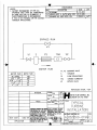
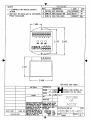
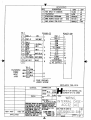
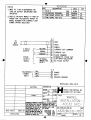
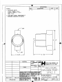
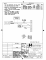
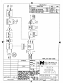
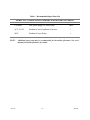
ACC-32
SIGNAL CONDITIONER
(AC Powered Version)
USER’S MANUAL
HP-248
September 2004
107 Kitty Hawk Lane, P.O. Box 2145, Elizabeth City, NC 27906-2145
800-628-4584 252-331-1997 FAX 252-331-2886
www.hofferflow.com E-mail: [email protected]
Notice
HOFFER FLOW CONTROLS, INC. MAKES NO WARRANTY OF ANY KIND
WITH REGARD TO THIS MATERIAL, INCLUDING, BUT NOT LIMITED TO,
THE IMPLIED WARRANTIES OF MERCHANTABILITY AND FITNESS FOR A
PARTICULAR PURPOSE.
This manual has been provided as an aid in installing, connecting, calibrating, operating, and
servicing this unit. Every precaution for accuracy has been taken in the preparation of this
manual; however, HOFFER FLOW CONTROLS, INC. neither assumes responsibility for any
omissions or errors that may appear nor assumes liability for any damages that may result from
the use of the products in accordance with information contained in the manual.
HOFFER FLOW CONTROLS' policy is to provide a user manual for each item supplied.
Therefore, all applicable user manuals should be examined before attempting to install or otherwise
connect a number of related subsystems.
During installation, care must be taken to select the correct interconnecting wiring drawing. The
choice of an incorrect connection drawing may result in damage to the system and/or one of the
components.
Please review the complete model number of each item to be connected and locate the appropriate
manual(s) and/or drawing(s). Identify all model numbers exactly before making any connections.
A number of options and accessories may be added to the main instrument, which are not shown
on the basic user wiring. Consult the appropriate option or accessory user manual before
connecting it to the system. In many cases, a system wiring drawing is available and may be
requested from HOFFER FLOW CONTROLS.
This document contains proprietary information, which is protected by copyright. All rights are
reserved. No part of this document may be photocopied, reproduced, or translated to another
language without the prior written consent of HOFFER FLOW CONTROLS, INC.
HOFFER FLOW CONTROLS’ policy is to make running changes, not model changes,
whenever an improvement is possible. This affords our customers the latest in technology and
engineering. The information contained in this document is subject to change without notice.
RETURN REQUESTS / INQUIRIES
Direct all warranty and repair requests/inquiries to the Hoffer Flow Controls Customer Service Department, telephone
number (252) 331-1997 or 1-800-628-4584. BEFORE RETURNING ANY PRODUCT(S) TO HOFFER FLOW
CONTROLS, PURCHASER MUST OBTAIN A RETURNED MATERIAL AUTHORIZATION (RMA) NUMBER FROM
HOFFER FLOW CONTROLS’ CUSTOMER SERVICE DEPARTMENT (IN ORDER TO AVOID PROCESSING
DELAYS). The assigned RMA number should then be marked on the outside of the return package and on any
correspondence.
FOR WARRANTY RETURNS, please have the
following information available BEFORE contacting
HOFFER FLOW CONTROLS:
1. P.O. number under which the product was
PURCHASED,
2. Model and serial number of the product under
warranty, and
3. Repair instructions and/or specific problems relative
to the product.
HFC 9708
FOR
REPAIRS
OR
NON-WARRANTY
consult
HOFFER
FLOW
CALIBRATIONS,
CONTROLS for current repair/calibration charges. Have
the following information available BEFORE contacting
HOFFER FLOW CONTROLS:
1. P.O. number to cover the COST of the
repair/calibration,
2. Model and serial number of the product, and
3. Repair instructions and/or specific problems relative
to the product.
LIMITED WARRANTY
HOFFER FLOW CONTROLS, INC. (“HFC”) warrants HFC’s products (“goods”) described in the specifications
incorporated in this manual to be free from defects in material and workmanship under normal use and service, but only
if such goods have been properly selected for the service intended, properly installed and properly operated and
maintained. This warranty shall extend for a period of (1) year from the date of delivery to the original purchaser (or
eighteen (18) months if the delivery to the original purchaser occurred outside the continental United States). This
warranty is extended only to the original purchaser (“Purchaser”). Purchaser’s sole and exclusive remedy is the repair
and/or replacement of nonconforming goods as provided in the following paragraphs.
In the event Purchaser believes the goods are defective, the goods must be returned to HFC, transportation prepaid by
Purchaser, within twelve (12) months after delivery of goods (or eighteen (18) months for goods delivered outside the
continental United States) for inspection by HFC. If HFC’s inspection determines that the workmanship or materials
are defective, the goods will be either repaired or replaced, at HFC’s sole determination, free of additional charge, and
the goods will be returned, transportation paid by HFC, using the lowest cost transportation available.
Prior to returning the goods to HFC, Purchaser must obtain a Returned Material Authorization (RMA) Number from
HFC’s Customer Service Department within 30 days after discovery of a purported breach of warranty, but no later than
the warranty period; otherwise, such claims shall be deemed waived. See the Return Requests/Inquiries Section of this
manual.
If HFC’s inspection reveals the goods are free of defects in material and workmanship or such inspection reveals the
goods were improperly used, improperly installed, and/or improperly selected for service intended, HFC will notify the
purchaser in writing and will deliver the goods back to purchaser upon (i) receipt of Purchaser’s written instructions
and (ii) the cost of transportation. If Purchaser does not respond within 30 days after notice from HFC, the goods will
be disposed of in HFC’s discretion.
HFC does not warrant these goods to meet the requirements of any safety code of any state, municipality, or any other
jurisdiction, and purchaser assumes all risk and liability whatsoever resulting from the use thereof, whether used singly
or in combination with other machines or apparatus.
This warranty shall not apply to any HFC goods or parts thereof, which have bee repaired outside HFC’s factory or
altered in any way, or have been subject to misuse, negligence, or accident, or have not been operated in accordance
with HFC’s printed instructions or have been operated under conditions more severe than, or otherwise exceeding, those
set forth in the specifications for such goods.
THIS WARRANTY IS EXPRESSLY IN LIEU OF ALL OTHER WARRANTIES, EXPRESSED OR IMPLIED,
INCLUDING ANY IMPLIED WARRANTLY OF MERCHANTABILITY OR FITNESS FOR A PARTICULAR
PURPOSE. HFC SHALL NOT BE LIABLE FOR ANY LOSS OR DAMAGE RESULTING, DIRECTLY OR INDIRECTLY,
FROM THE USE OF LOSS OF USE OF THE GOODS. WITHOUT LIMITING THE GENERALITY OF THE FOREGOING, THIS
EXCLUSION FROM LIABILITY EMBRACES THE PURCHASER’S EXPENSES FOR DOWNTIME, DAMAGES FOR WHICH
THE PURCHASER MAY BE LIABLE TO OTHER PERSONS, DAMAGES TO PROPERTY, AND INJURY TO OR DEATH OF
ANY PERSON. HFC NEITHER ASSUMES NOR AUTHORIZES ANY PERSON TO ASSUME FOR IT ANY OTHER
LIABILITY IN CONNECTION WITH THE SALE OR USE OF HFC’S GOODS, AND THERE ARE NO AGREEMENTS OR
WARRANTIES COLLATERAL TO OR AFFECTING THE AGREEMENT. PURCHASER’S SOLE AND EXCLUSIVE REMEDY
IS THE REPAIR AND/OR REPLACEMENT OF NONCONFORMING GOODS AS PROVIDED IN THE PRECEDING
PARAGRAPHS. HFC SHALL NOT BE LIABLE FOR ANY OTHER DAMAGES WHATSOEVER INCLUDING INDIRECT,
INCIDENTAL, OR CONSEQUENTIAL DAMAGES.
Disclaimer:
Specifications are subject to change without notice.
Some pages are left intentionally blank.
HFC 9708
TABLE OF CONTENTS
SECTION I
INTRODUCTION AND SPECIFICATIONS................................................................1.1
SECTION II
INSTALLATION ...........................................................................................................2.1
SECTION III
CALIBRATION .............................................................................................................3.1
SECTION IV
OPERATION .................................................................................................................4.1
SECTION V
MAINTENANCE AND SCHEMATIC ..........................................................................5.1
SECTION I
ACC-32 MODULATED CARRIER CONDITIONER/VOLTAGE CONVERTER
The ACC-32 Modulated Carrier Conditioner/Converter is an active pickoff accessory for the turbine
flowmeter which provides a pulse output and an analog voltage output proportional to flowrate.
The Modulated Carrier principle eliminates the pickoff drag, associated with conventional magnetic
pickoffs, resulting in a significant increase in the usable range of a turbine flowmeter at lower rates.
The ACC-32 excites a series MCP pickup mounted on the turbine flowmeter. Sensed through the
flowmeter body, the motion of the turbine rotor modulates the coil field, subsequent conditioning
provides a pulse output signal where each pulse is representative of a discrete volume of fluid and where
the frequency is proportional to flowrate. Pulse scaling is optionally available to reduce output pulse
rate where required.
The analog output is generated by passing the pulse output frequency signal to a frequency to the
voltage converter to generate a voltage proportional to flowrate.
Flowmeters compatible with the ACC-32 are available in nominal sizes below two inches. Larger
flowmeters do not require a modulated carrier pickup.
SPECIFICATIONS
INPUT
Pickup Type - Compatible with Series MCP pickoff.
Transmission distance dependent on output waveform and drive
requirements.
Cable type Beldon 8422.
Modulation frequency range 10 Hz - 3500 Hz.
PULSE OUTPUT
(Square Waveform)
Open collector VMOS transistor 2N6660.
Maximum OFF state voltage 60 VDC.
Maximum ON current 1.0 amps.
TTL/CMOS fanout of 10 TTL/CMOS loads.
AC capacitively coupled square wave.
PULSE SCALING
CAPABILITY
(OPTIONAL)
÷2, ÷4, ÷8, ÷16, ÷32, ÷64, ÷128, ÷256
ACC-32
1.1
HP-248
ORDERING INFORMATION
MODEL ACC32-( A )-( B )-( C )-( D )-( E )
PULSE OUTPUT
ANALOG OUTPUT
INPUT POWER
OPTIONAL FEATURE
ENCLOSURE STYLE
PULSE OUTPUT
MODEL ACC32-( A )-( )-( )-( )-( )
OPTION ( A )
(1)
OPEN COLLECTOR
(2)
(2) TTL/CMOS
(3)
AC SQUARE WAVE
(5)
0-10 V SQUARE WAVE
ANALOG OUTPUT
MODEL ACC32-( )-( B )-(
OPTION ( B )
(X)
NONE
(C)
4-20 MA
)-(
)-(
INPUT POWER
MODEL ACC32-( )-( )-( C )-( )-(
OPTION ( C )
(A)
115 VAC 50/60 HZ
(B)
220 VAC 50/60 HZ
(D)
15-35 VDC
)
)
OPTIONAL FEATURE
MODEL ACC32-( )-( )-( )-( D )-( )
OPTION ( D )
(PS)
DIP SWITCH SELECTABLE
DIVIDE BY 2,4,8,16,32,64,128, 256
ENCLOSURE STYLE
MODEL ACC32-( )-( )-( )-( )-( E )
OPTION ( E )
(2)
STYLE 2 CASE, GENERAL PURPOSE
(4/O)
NOTE:
ACC-32
STYLE 4 CASE, EXPLOSION-PROOF WITH WATER TIGHT ‘O’ RING
MEETS CLASS I, GROUP C, D (ADALET CASE, XJS WITH FLAT COVER), STOCK #200-0698
CLASS II, GROUPS E, F & G
CLASS III
INSERT (X) IN MODEL NUMBER FOR EVERY OPTION NOT SPECIFIED.
1.1
HP-248
SECTION II
FLOWMETER INSTALLATION
GENERAL
Proper application of the turbine flowmeter requires a suitable piping installation in order to achieve
accurate and reliable operation.
The piping configuration immediately preceding and following the flowmeter is termed the meter run.
Refer to the manufacturer’s outline and installation instructions when installing the flowmeter and meter
run.
RELATIVE - The performance of the turbine flowmeter is affected by the fluid swirl and non-uniform
velocity profiles. The following recommendation will reduce such flow irregularities.
It is advisable not to locate the meter run immediately downstream of pumps, partially opened valves,
bends or other similar piping configurations. In addition, the area surrounding the flowmeter should be
free of sources of electrical noise such as motors, solenoids, transformers and power lines which may be
coupled to the pickoff device.
The metering section should not be subjected to excessive vibration or shock. Such a condition may
result in an mechanically induced output signal from the pickoff device.
METER RUN - In general, the meter run should be chosen to have the same inner diameter as the
meter bore. A minimum of 10 pipe diameters of straight pipe upstream and 5 pipe diameters
downstream are required. Where this optimum line configuration can not be implemented, it is advisable
to install a flow straightener properly positioned upstream of the flowmeter. Orientation is not a critical
factor, however, horizontal is a preferred orientation.
BYPASS RUN - A properly sized bypass run with suitable blocking valves may be equipped where an
interruption in fluid flow for turbine meters servicing can not be tolerated.
STRAINER - A strainer, filter and/or air eliminator is recommended to reduce the potential of fouling
or damage. See table for recommended mesh size.
On initial startup of a line, it is advisable to install a spool piece purging the line to eliminate damaging the
flowmeter, due to flux, tape, solder, welds or other contaminates carried along by the fluid stream.
CAVITATION - Cavitation causes measurement inaccuracies in turbine flowmeter and should be
avoided by suitable line and operating configurations.
Whenever the pressure within a pipeline instantaneously falls below the equilibrium vapor pressure of the
fluid, a portion of the fluid vaporizes and forms bubbles in the pipeline. This is termed cavitation.
Cavitation is eliminated by maintaining adequate back pressure on the flowmeter. A downstream valve
that provides the necessary back pressure is one means for preventing cavitation in the metering run.
Control valves should be located downstream, if possible. Some installations may also make use of a
vapor eliminator upstream of the flowmeter.
The minimum required back pressure may be estimated using Error! Reference source not found.:
Min: Back Pressure = 1.25 X Vapor Pressure + 2 X Pressure Drop
ACC-32
2.1
HP-248
INSTALLATION WIRING LAYOUT FOR INTERCONNECTIONS USING MCP PICKUP
In considering the interconnection between the flowmeter and the flow measurement system some
attention must be given to anticipated noise sources and to the coupling of these noise sources to the
interconnecting wiring.
Noise signals may be coupled inductively or capacitvely into the wiring between the flowmeter and the
electronic measuring systems. In general, utilizing a shielded, twisted pair for the interconnection greatly
reduces this coupling. The shield should be grounded on one end of the cable only. In general,
grounding only on the electronic measuring system is best.
However, even with proper interconnecting cabling crosstalk with other signal lines or power lines may
still occur and should be avoided. Physical isolation in the manner in which the wiring is run reduces the
chances of potential problems.
The turbine flowmeter equipped with a Modulated Carrier Pickup (MCP) should not be located more
than 100 feet from the Modulated Carrier Conditioner. It is recommended that the Modulated Carrier
Conditioner be installed on or near the flowmeter to assure proper operation. Enclosures suitable for
mounting in hazardous and wet areas are available.
INSTALLATION OF ACC-32 (AC POWERED)
The Model ACC-32 should be placed in a convenient location which maintains access to the unit should
repairs or readjustment be required.
Refer to outline and installation drawing for the appropriate case type to be installed. Drill appropriate
mounting holes as required.
Refer to wiring installation drawing for the appropriate terminals for interconnections. Connections to the
terminal block should be carefully dressed to avoid having bare wires extend pass the screw clamp on
the terminal block. Wires should be neatly dressed near bottom of enclosure to assure wiring will not
become fouled when cover is installed.
Connect two conductor shielded cables from flowmeter. Connect shield to ACC-32 only.
Line power connection should be made through a circuit breaker so that power can be turned off while
servicing accessory model. Power is 117V or 220/240 VAC. An earth ground connection is also
required.
Connect pulse output is used, several output pulse waveforms are available factory equipped. Wire to
appropriate terminal for waveform desired and specified.
If the analog output has been equipped connect wiring to appropriate terminals and load. A shielded,
twisted pair wire is recommended. Ground shield on one end only. Use some precautions as described
for flowmeter input signal.
ACC-32
2.2
HP-248
SECTION III
CALIBRATION OF ANALOG OUTPUT - GENERAL CONSIDERATIONS
(LIQUID APPLICATIONS)
INTRODUCTION
In general, all flow measurement systems supplied by Hoffer Flow Controls have been factory
calibrated as specified by the user, at the time of purchase, free of charge.
All systems which underwent such a factory calibration have a calibration card attached prior to
shipment. This card contains the details of analog outputs, as well as other useful calibration data.
Field calibration is only required when a change has occurred or is sought to the measuring system.
Such a change may be due to repair, replacement or recalibration of the flowmeter, or perhaps a change
in the analog output span.
PROCEDURE
Begin by determining the equivalent maximum volumetric flowrate in GPM, expected by the application,
term this GPM (MAX). GPM (MAX) may be calculated based on the analog output scale requirements
or may be the maximum flowrate listed on the flowmeter’s calibration sheet.
From the calibration constant (or K Factor) listed on the data sheet for the flowmeter, obtain the
frequency corresponding to GPM (MAX) using Equation 1 and designate this frequency F (MAX).
Equation 1
F MAX = K AVG X GPM MAX
60
FOR ANALOG OPTION
The analog output of the ACC-32 may be calibrated with the aid of an external oscillator used in
conjunction with a frequency counter.
The external oscillator is used to supply a test frequency. In this method, the external oscillator is
connected to the signal input terminals as shown in Figure 1. The oscillator’s output frequency is set to
equal F (MAX) as indicated on the frequency counter.
1. The course range adjustment is accomplished by selecting a switch position on a DIP switch located
on the PCA-58 printed circuit card. See Table A to determine required switch position and set into
switch as shown on drawing ACC-32-403 for anticipated F MAX.
ACC-32
3.1
HP-248
NOTE:
It is necessary to open the cover of the enclosure by removing two screws on the
side of the box and lifting cover. Two printed circuit cards are attached. The
“RANGE” Dip Switch may be programmed with a pen. Input power should be
removed during this step.
2. Connect a digital milliampmeter or equivalent, across the voltage output terminals.
3. Adjust SPAN control fully counter clockwise or 20 turns.
4. Adjust ZERO control for desired zero current (i.e., 4 mA).
5. Inject the Test Frequency equal to F (MAX) while adjusting SPAN for current equal to 20 mA.
See test setup shown in Figure 1.
NOTE:
Iterate steps 4 and 5 until no change is observed.
Table A
F (MAX)
75
150
300
600
1200
ACC-32
TO 150
TO 300
TO 600
TO 1200
TO 2400
RANGE SELECT
SWITCH POSITION
1
2
3
4
5
3.2
HP-248
SECTION IV
OPERATION
INITIAL STARTUP
Perform any purging of piping with spool piece in place. Once completed, install the flowmeter and
connect cabling to pickup coil. If false counting action occurs turn sensitivity control counterclockwise.
INTRODUCTION
The pulse output and analog output commence with flow through the flowmeter.
For the analog output, the span is that established by either the factory calibration or field calibration.
The range is 4-20 mA into a maximum of 375 ohms of loop resistance.
PRINCIPLE OF OPERATION
A simplified block diagram of the ACC-32 Modulated Carrier Conditioner/Converter is given on the
drawing ACC-32-601. Key functional blocks, as well as, information flow are designated. The basic
operation of the system is as follows.
The MCP on the turbine flowmeter is connected to the Model ACC-32 with a shielded twisted pair
signal cable. The MCP pickup coil forms part of an oscillator circuit and is excited by the ACC-32.
Motion of the turbine rotor modulates the oscillator output. A demodulator converts the AM signal to a
signal at a frequency determined by the rotor speed. The low level demodulated signal is then passed
through a signal conditioning chain where it is filtered, amplified and shaped into a train of digital pulses
whose frequency is related to the volume flowrate and where each pulse represents a discrete volume of
fluid.
ANALOG OUTPUT
The signal entering the frequency to analog converter is passed through a combination of a divide by N
and a DIP switch MATRIX. The QN output is chosen whose pulse rate is between 75 and 150 Hz at
the maximum flowrate to be measured. This scaled pulse rate is fed to a precision monostable circuit.
The output of the monostable is then filtered into an analog voltage that is proportional to volumetric
flowrate.
The output amplifier is a voltage to current amplifier. If offers zero and span available in a standard
process range of 4 to 20 mA.
POWER SUPPLY
The power supply provides for operating bias voltage for all internal circuitry.
The output amplifier may be configured to provide one of the following:
1. High level AC square wave (Capacitively coupled).
2. Open collector transistor.
3. TTL/CMOS compatible square pulse of 5 volt amplitude.
The output amplifier is buffered from the signal driving the analog output.
ACC-32
4.1
HP-248
SECTION V
MAINTENANCE, GENERAL
Hoffer Flow Controls Flow Measurement Systems are constructed to give a long service life in the
targeted measuring field and service environment. However, problems do occur form time to time and
the following points should be considered for preventive maintenance and repairs.
The bearing type used in the flowmeter was chosen to give compromise between long life, chemical
resistance, ease of maintenance and performance. A preventive maintenance schedule should be
established to determine the amount of wear which has occurred since last overhaul. See user's manual
for flowmeter for further instructions.
A spare parts list has been provided which at the discretion of the user, may be user stocked. Consult
with the manufacturer if an abridged spare parts list is sought. The recommended spare parts list may be
found following this section and in the user's manual for the flowmeter.
In case the flow measurement system malfunctions or becomes inoperative, a troubleshooting procedure
is enclosed.
Factory consultation is available to assist in diagnosing problems. In addition, factory repair parts and
service are available for individuals who wish to utilize this service.
A complete set of schematic diagrams for all printed cards is available from Hoffer Flow Controls for
users who wish their own personnel to service the measuring systems.
NOTE:
♦ All printed circuit cards are warranted for one year after date of sale.
♦ All printed circuit cards may be factory repaired at a nominal fee for parts and labor after
warrantee period.
TROUBLESHOOTING AND MAINTENANCE
INTRODUCTION
In case of an inoperable or malfunctioning system the following procedures can be used to isolate the
faulty wiring, printed circuit boards and/or alternate causes. The majority of repairs can be made in the
field thereby reducing the time a unit is out of service.
A recommended spare parts list is given immediately following the troubleshooting portion of this
manual. The necessary documentation is contained with this manual with the exception of the calibration
data sheet for the turbine flowmeter. This calibration is supplied separately.
Factory consultation is available to assist in diagnosing problems. Note that in some cases factory
repairs can be performed more easily than can be accomplished in the field.
Failure conditions are listed and the possible corrective actions given to eliminate the observed problem.
GENERAL INSPECTION TO DETERMINE IF UNIT IS OPERATING PROPERLY
Proper operation of the ACC-32 can be assumed when with power applied to the unit:
1. The pulse output produces a pulse train of the desired amplitude when flow through the flow
transducer occurs.
2. The analog output produces a voltage output signal of 4-20 mA with a span corresponding to that
established by the calibration procedure.
ACC-32
5.1
HP-248
OBSERVED CONDITION
PROBLEM/CORRECTIVE ACTION
A. NO PULSE OUTPUT
1. Inspect terminal strip wiring for conformity
to the installation instructions and for
acceptance workmanship.
2. Verify fuse is good with an ohm meter. See
dwg. ACC-32-403. (AC power only).
3. Determine if flowmeter rotor is fouled.
4. Defective pickup coil. Replace MCP.
5. Defective cable. Replace.
6. Defective ACC-32. Repair or replace.
B. PULSING OUTPUT WITH NO FLOW
1. Input voltage below limits.
2. Defective pickup coil. Replace.
3. Defective cable. Replace.
4. Defective ACC-32. Repair or replace.
C. ANALOG OUTPUT MALFUNCTION
1. Improper wiring termination. Correct
wiring.
2. ACC-32 improperly calibrated.
Recalibrate.
3. Defective circuitry within the ACC-32.
Factory repair ACC-32.
NOTE:
ACC-32
Refer to flowmeter user's manual for repair instructions for the turbine flowmeter.
5.2
HP-248
Table 1 - Recommended Spare Parts List
MODEL ACC-32 MODULATED CARRIER CONDITIONER/CONVERTER
PART NUMBER
DESCRIPTION
QUANTITY
1/20 AMP
Fuse, power supply (AC Power Only)
ACC-32-XX
Modulated Carrier/Conditioner/Converter
1
MCP
Modulated Carrier Pickup
1
NOTE:
ACC-32
1 Box
Additional spare parts may be recommended for the turbine flowmeter. See user's
manual for turbine flowmeter for details.
5.3
HP-248