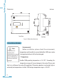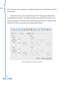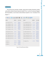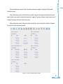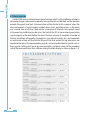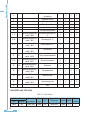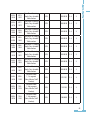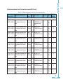
1
AcuRev 1300 3P4W Energy Meter User's Manual AcuRev 1300 CopyRight © 2015 V2.02 This manual may not be altered or reproduced in whole or in part by any means without the expressed written consent of Accuenergy. The information contained in this document is believed to be accurate at the time of publication, however, Accuenergy assumes no responsibility for any errors which may appear here and reserves the right to make changes without notice. Please ask the local representative for latest product specifications before ordering. [Document #2300E2202 Revision Date: Sep., 2015] I AcuRev 1300 Please read this manual carefully before installation, operation and maintenance of AcuRev 1300 series meter. The following symbols in this manual are used to provide warning of danger or risk during the installation and operation of the meters. Electric Shock Symbol: Carries information about procedures which must be followed to reduce the risk of electric shock and danger to personal health. Safety Alert Symbol: Carries information about circumstances which if not considered may result in injury or death. Prior to maintenance and repair, the equipment must be de-energized and grounded. All maintenance work must be performed by qualified, competent accredited professionals who have received formal training and have experience with highvoltage and currentdevices. Accuenergy shall not be responsible or liable for any damages or injuries caused by improper meter installation and/or operation. II AcuRev 1300 Content Chapter 1 Introduction-------------------------------------------------------------------------------------1 1.1 Meter Overview--------------------------------------------------------------------------2 1.2 Areas of Application--------------------------------------------------------------------------3 1.3 Product Features-------------------------------------------------------------------3 Chapter 2 Installation--------------------------------------------------------------------------------------5 2.1 Appearance and Dimensions---------------------------------------------------------7 2.2 Installation Methods---------------------------------------------------------8 2.3 Wiring-----------------------------------------------------------------------------------------------12 Chapter 3 Operation and Application-----------------------------------------------------------23 3.1 Display Panel and Keys-----------------------------------------------------------------24 3.2 Display Mode and Key Operations-----------------------------------------------------------25 3.3 Parameter Display and Key Operations-----------------------------------------------------30 3.4 Settings and Operations-----------------------------------------------------------------31 Chapter 4 Functions and Software----------------------------------------------------------35 4.1 Parameter settings----------------------------------------------------------36 4.2 Basic Measurement Functions----------------------------------------------------------40 4.3 Measurement Functions----------------------------------------------------------40 4.4 Demand------------------------------------------------------------------------------------------47 4 . 5 R O Fu n c t i o n s - - - - - - - - - - - - - - - - - - - - - - - - - - - - - - - - - - - - - - - - - - - - - - - - - - - - - - - - - - 4 8 4.6 EventLogging--------------------------------------------------------------------------------48 III AcuRev 1300 4.7 Alarm Functions---------------------------------------------------------------------------------50 4.8 Incorrect Connection Detection----------------------------------------------------------54 4.9 Instrument Information----------------------------------------------------------56 4.10 Sealing function---------------------------------------------------------------------------56 Chapter 5 Communication-------------------------------------------------------------------------61 5.1 Modbus Protocol Introduction-------------------------------------------------------------62 5.2 Communication Format------------------------------------------------------------------------65 5.3 Application Details------------------------------------------------------------------------------70 Appendix-------------------------------------------------------------------------------------105 Appendix A Function List--------------------------------------------------------------------------106 Appendix B Technical Data and Specification-------------------------------------------------107 Appendix C Ordering Information---------------------------------------------------------------109 Appendix D Revision History----------------------------------------------------------------------110 IV AcuRev 1300 Welcome to AcuRev 1300! You have purchased an advanced, versatile, multifunction power meter. Please note the following chapter descriptions in order to utilize the power meter properly. Chapter 1 Introduces the basic AcuRev 1300 features and application areas. Chapter 2 Introduces AcuRev 1300 installation and wiring methods in detail. Chapter 3 walks through how to operate AcuRev 1300 via the display panel, display measurement data and parameter settings. Chapter 4 introduces main functions with the included software. Chapter 5 introduces communication related informations, including communication protocol format and parameter address table. Appendix provides AcuRev 1300 technical specifications and ordering information. V VI AcuRev 1300 AcuRev 1300 Chapter 1 Introduction 1.1 Meter Overview 1.2 Areas of Application 1.3 Product Features 1 AcuRev 1300 1.1 Meter Overview AcuRev 1300 series rail-mounted three phase energy Meters has a small size and high accuracy, it is ideal for use in distributor and tight spaces. The meter is equipped with an easy to read liquid crystal display (LCD) which displays all the important information. It is ideal for building energy management systems, energy monitoring and energy metering systems. Energy AcuRev1300 series support Bi-directional active energy measurements; Two-way reactive power energy metering, four quadrant reactive power energy metering; Twoway apparent energy metering; The cumulative energy metering (Energy Import + Energy Export); Net energy metering (input power - power output); Support rate 4 electric energy metering. Measurement fuction AcuRev 1300 series meters provide measurement and indication functions. Which can measure Voltage, Current, Power, Frequency and Power Factor. And which also have load characteristics indication function. Line current measurement ,The calculation of zero sequence current.Different specifications of the meters have different functions. Demand This product provides demand forecasting demand measurement and demand climax of Current, Active Power, Reactive Power and Apparent Power. System Event Logging The product can record the time and event ID about some important parameter amendment or clearance. 2 Running time detection AcuRev 1300 Support instrument running time of detection and instructions. Instrument operation temperature indication Provide instrument internal temperature indicator Alarm function Support multiple parameter data detection alarm, and can be configured to RO output. Communication Supports RS485 communication open protocol and infrared interface. Support Modbus RTU. Infrared interface supports the on spot infrared meter reading. 1.2 Areas of Application Large commercial center School Hotels and Buildings Smart building system Industrial environment Rail transport Public facilities Smart distribution cabinet Energy management system Energy saving system 1.3 Product Features Multifunction, high accuracy AcuRev 1300 series meter has data collection and management function, energy measurement and multi-parameters measurement function, and demand measurement, event logging. The measurement accuracy of energy, power, voltage, current is 0.5. Small size, convenient installation 3 AcuRev 1300 AcuRev 1300 series product appearance and dimension fits the IEC 35mm DIN standard, accounts for only 6 mold. Display is clear The LCD display is very clear. All measurement parameters could be search through the display easily. The parameter could be set through the display. LCD display has backlight support, which can help users use it in wake light environment. Safety AcuRev 1300 series product has electronic sealing function and physical sealing. Users cannot change the parameters through the keys when the electronic sealing closed, and important parameters cannot be changed through communication, preventing maliciousdata changement. Convenient wiring Both high pressure system and low pressure systems, both three-phase threewire system and three-phase four-wire system, can choose the appropriate wiring way connected to AcuRev1300 series instrument.Almost all of the three-phase system application, and can be used for single phase system. Connection error automatic judgment AcuRev 1300 series instrument connection errors of judgment and help in the process of the project construction cost increase caused by the wrong wiring. 4 AcuRev 1300 Chapter 2 Installation 2.1 Appearance and Dimensions 2.2 Installation Methods 2.3 Wiring 5 AcuRev 1300 Before Installtion The installation must be perfomred by qualified, competent accredited professionals who have received formal training and have experience with high voltage and current devices. Appropriate safety wear (gloves, glasses, arc flush suit, etc.) is mandatory to ensure safe installation. During normal meter operation, caution should be used when handling the following as high voltage may be present: Terminal Blocks, Current Transformer connection nodes, Potential Transformer connection nodes and the related circuits. All primary and secondary circuits may contain lethal current and voltage. Contact with current channels must be avoided. The power meter and I/O modules cannot be installed on the primary side of transformers or where VA has limitations. The power meter can be only installed on the secondary side. Avoid contact with meter terminals after the completion of installtion. Do not input voltage above the rated maximum limit of the power meter and devices connected to it. Before energizing the meter, please refer to the meter's label and specifications. Do not perform high voltage test / insulation experiment to output, input or communication terminals. The use of shorting blocks and fuses are recommended. Current transformers need to be grounded. Use dry cloth to wipe the meter. The replace of the Battery must be performed by professionals. 6 AcuRev 1300 This chapter mainly described how to install an AcuRev 1300 series meter, which is a very important step of using the meter correctly. This chapter gives some pictures about how to install the meter and some notes. Before installing the meter, please read this first. 2.1 Appearance and Dimensions Appearance: Figure 2-1 AcuRev 1300 Appearance 7 AcuRev 1300 Dimensions: Unit: mm Front View Side View Figure 2-2 Meter base dimensions 2.2 Installation Methods Note Temperature and humidity of the environment must accord with the requirement of acurev 1300, Otherwise it may cause the meter damaged. Environmental Before installation, please check the environment, temperature and humidity to ensure theAcuRev 1300 series meter is being placed where it will not be damaged. 1. Temperature AcuRev 1300 operating temperature is -25~70°C. Exceeding this temperature range will cause damage to the meter. Please note that it can influence the meter life negatively if themeter operates in extremely high or extremely low temperatures. AcuRev 1300 storage temperature range is -40~85°C. 8 AcuRev 1300 2. Humidity 5% to 95% non-condensing. 3. Location AcuRev1300 series meter should be installed in a dry and dust free environment. Avoidexposing meter to excessive heat, radiation and high electrical noise sources. Installation Steps: This product is DIN railed mounted and fits on the standard 35mm rail. 1. To install the meter on the rail insert the top of the rail into the groove on the back of the meter.Pull the metal clips back and slide the rail across the groove of the meter. Installation Rail Figure 2-3 Step A 2. Use the metal clips to tighten the rail to complete installation. 9 AcuRev 1300 Figure 2-4 Step B 3. Before mentioning this step, the steps needed to remove the seal/cover need to be mentioned. I.E. Step 5 below should come first.To attach seal/cover back onto the meter place the left side of the cover down onto meter and press down on the right side. When installed correctly you will hear a clicking sound.The steps to attach the other cover is opposite to the above step. Figure 2-5 Step C 10 Figure 2-6 Step D 5. To open the cover, remove the seal if applicable, unscrew the sealing screws and life the cover upwards to remove. Figure 2-7 Step E 11 AcuRev 1300 4. After inserting the cover, tighten the sealing screws and lay the seal and tighten the sealing screws, lay the seal. AcuRev 1300 2.3 Wiring Terminals: This manual use L1 L2 L3 to represent three-phase current loop, which are the same as A, B, C in other manuals. Figure 2-8 The transformer AcuRev1300 terminal access type distribution A, B, S: communications terminal; P1, P2: pulse output; L, N: auxiliary power; V1, V2, V3 and.Vn: voltage circuit; I11, I12, I21 I22, I31, I32, I41, I42: current loop; R1, R2: RO output. AuxiliaryPower Supply: AcuRev1300 series instrument power supply: ac 100 ~ 415 vac, 50/60 hz, or dc 100300 VDC, can be used throughout the world. Other power supply voltage selection please contact manufacturers. Instrument in the typical working conditions of power consumption is very small, so the power supply can by independent power supply, can also be obtained from circuit under test.Suggested that under the condition of power voltage fluctuation is bigger, use the voltagee stabilizer. Power supply terminals, respectively is: L, N. The typical auxiliary power wiring is as follows: 12 AcuRev 1300 AcuRec1300 Choice of wire of power supply is AWG22-16 or 0.6-1.5mm2. A fuse (typical 1A/250Vac) or small air circuit breaker should be used in the auxillary power supply loop. Such as the use of small air circuit breaker, it is recommended to use IEC947 standards and through the CE certification of products. An isolated transformer or EMC filter should be used in the control power supply loop if there is a power quality problem in the power supply. Note: the power before wiring, please confirm that the current power supply and instrument brand logo on the power supply voltage is up! Voltage Input: Maximum input voltage for the AcuRev1300 series meter shall not exceed 400LN/690LL VAC rms for three phase or 400LN VAC rms for single phase. Voltage input signal circuit must be installed in the air circuit breaker, fuse or small suggestion with 1 a fuse. Potential Transformer (PT) must be used for high voltage systems. Typical secondary output for PTs shall be 100V or 120V. Please make sure to select an appropriate PT to maintain the measurement accuracy of the meter. When connecting using the star configuration wiring method, the PT's primary side rated voltage should be equal to or close to the phase voltage of the system to utilize the full range of the PT. When connecting using the delta configuration wiring method, the PT's primary side rated voltage should be equal to or close to the line voltage of the system. A fuse (typical 1A/250Vac) should be used in the voltage input loop. The wire for voltage input is AWG16-12 or 1.3-2.0mm2. 13 AcuRev 1300 Note: In no circumstance should the secondary of the PT be shorted. The secondary of the PT should be grounded at one end. Please refer to the wiring diagram section for further details. Current Input: Current Transformers (CTs) are required in most engineering applications. Typical current rating for the secondary side of the CT shall be 5A (standard) or 1A (Optional), please refer to the ordering information appendix for further details. CTs must be used if the system rated current is over 5A. The accuracy of the CT should be better than 0.5% with rating over 3VA is recommended in order to preserve the meter's accuracy. The wire between CTs and the meter shall be as short as possible. The length of the wire have an effect on the accuracy.The wire size of current input is AWG15-10 or 1.5-2.5mm2. Note: The secondary side of the CT should not be open circuit in any circumstance when the power is on. There should not be any fuse or switch in the CT loop. One end of the CT loop should be connected to the ground. Vn Connection: Vn is the reference point of the Acuvim II series meter voltage input. Low wire resistance helps improve the measurement accuracy. Different system wiring modes require different Vn connection methods. Please refer to the wiring diagram section for more details. AcuRev1300 series instrument measuring wiring method AcuRev1300 series instrument can satisfy almost any kind of three phase wiring diagrams. Please read this section carefully before choosing the suitable wiring method for your power system. Please make sure the rated voltage grade and PT secondary side voltage is suitable for the current models of AcuRev1300 series. Current rating and CT secondary side current rating is suitable for the current models of AcuRev1300 series. 14 1). 3LN, 3CT; The connection mode set to 3LN LINE A B C N 1A FUSE Terminal Block I11 I12 I21 I22 I31 I32 I41 I42 VN V3 V2 V1 AcuRev 1300 LOAD 15 AcuRev 1300 AcuRev1300 series instrument connection mode Settings and the corresponding practical application in engineering and correct, to ensure the measurement accuracy of instrument. AcuRev 1300 2). 2LL,3CT (using 2CT); The connection mode is set to 2LL; Note: output transformer secondary side is 5A/1A LINE A B C 1A FUSE Terminal Block I11 I12 I21 I22 I31 I32 I41 I42 LOAD 16 VN V3 V2 V1 AcuRev 1300 LINE A B C 1A FUSE Terminal Block I11 I12 I21 I22 I31 I32 I41 I42 VN V3 V2 V1 AcuRev 1300 LOAD 17 AcuRev 1300 3). 2LL,2CT;The connection mode is set to 2LL; Note: mutual inductance type secondary side output for 5A/1A,Rogowski coil 333mV,200mA AcuRev 1300 4). 1LL , 2CT; the connection mode is set to 1LL. LINE A N B 1A FUSE Terminal Block I11 I12 I21 I22 I31 I32 I41 I42 LOAD 18 VN V3 V2 V1 AcuRev 1300 AcuRev 1300 5) 1LN, 1CT; connection mode is set to 1LN LINE A N 1A FUSE Terminal Block I11 I12 I21 I22 I31 I32 I41 I42 VN V3 V2 V1 AcuRev 1300 LOAD 19 AcuRev 1300 Relay output wiring diagram 220Vac L R1 Relay Output R2 20 V+ N G Auxiliary Power Supply com If the master device does not have RS485 but RS232 port, a RS232/485 converter can beutilized. Typical RS485 network topologies include line, circle and star. In order to improve communication quality, please pay attention to: 1. High-quality Shielded Twisted Pair cable is very important, AWG22 (0.6mm2) or lower isrecommended. Two cables should be different colors. 2. Pay attention to "single point earthing". It means there is only one point of the shieldingconnected to ground in a single communication link. 3. Every A(+) should be connected to A(+), B(-) to B(-), or it will influence the network, evendamage the communication interface. 4. "T" type connection topology should be avoided. This means no new branches exceptfrom the starting point. 5.Keep communication cables away as much as possible from sources of electrical noise.When several devices are connected (daisy chain) to the same long communication line, ananti signalrefecting resistor (typical value 120- 300Ohm, 0.25W) is often used at the endof the circuit (the last meter of the chain) if the communication quality is distorted. 6. Use RS232/RS485 or USB/RS485 converter with optical isolated output and surge protection. 7. A infrared port is also available in the Display Module, which supports meterreading. 21 AcuRev 1300 AcuRev1300 communication utilizes RS485 port, via Modbus-RTU protocol. The wiringterminals are A, B, S. "A" is called differential signal " ", "B" is called differentialsignal"-", "S" is connected to the shielding of shielded twisted pair cable. The maximumdistance of Shielded Twisted Pair cable is 1200 m. The distance will be shorter if moredevices are on the same communication link or using a higher baud rate. 22 AcuRev 1300 AcuRev 1300 Chapter 3 Operation and Application 3.1 Display Panel and Keys 3.2 Display Mode and Key Operations 3.3 Parameter Display and Key Operations 3.4 Settings and Operations 23 AcuRev 1300 In this chapter, you would see some details about human-computer interaction, including how to use the key to browse demanded information, and how to set the parameters correctly. 3.1 Display Panel and Keys Chapter 2.1 shows the dimensions of Display Module. It consists of one LCD screen and one key. To make the description clearly, all of the chars and number segments are lighten in the picture below, but when we use it , they would not appear in one page. 1 2 3 4 5 6 7 8 9 Figure 3-1 All LCD display lighten Table 3-1 Display of content NO. 1 2 3 4 5 24 Content Description To display what kind of parameter in the display area. Description area To distinguish the power of conjunction, split phase, current, demand, parameter Settings, and so on. To display the main measurement parameters: Measurement parameter display area Energy, Voltage, Current, Power, Frequency, Demand, 7 decimal point, time signal Settings, Time. Indicate the all information mode No icon: no communication; One icon: query sent Communication icon Two icons: query sent and response received Display in the analog way according to the load Load size icon frequency 7 8 9 Load character indicate unit AcuRev 1300 Four-quadrant reactive power display 6 To indicate the first to forth quadrant reactive power Import icon on: display the Energy Import Export icon on: display the Energy Export Inductance icon on: inductive load Capacitor icon on: capacitive load Unit of the parameter in parameter display area 3.2 Display Mode and Key Operations The LCD display consists of important parameter display mode, all parameter display mode and setting mode. 1. Important parameter display mode The important parameter display area mode mainly display the important parameters, including system default display data and custom data. Each page display lasts about 6 seconds. When we press “SCROLL” in a short time, the current screen content would be locked for 1 minute and light up the backlight, during this time, press the same key in the same way another time, it would turn to the next page and lock the display for 1 minute; when we didn’t press any key for one minute, then it would display all the pages in a rate of 6 second per page automatically. System default display content: A) the input active power (AcuRev1301 ~ AcuRev1304 support) B) the output active power (AcuRev1302 ~ AcuRev1304 support) Custom data content: The 11th -42th screen data could be set to important parameter display mode, and be cycle displayed. See table 3-2 Display coding table. Note: Configuration 1: using the communication way , we could add 1 to the corresponding 25 AcuRev 1300 flag, the consequence would be added to the important parameter display area to cycle display. The corresponding flag would be cleared and expelled from important parameters. System default display data content cannot be deleted.Configuration 2: add or delete the corresponding number through pressing keys. AcuRev1300 instrument power value is positive.The number of significant digits when electricity data (including the number of decimal places) less than 7, normal display; When effective digit is greater than 7, the data in "thousand", for display. 2. All parameters display mode AcuRev1300 instrument power value is positive.The number of significant digits when electricity data (including the number of decimal places) less than 7, normal display; When effective digit is greater than 7, the data in "thousand", for display. AcuRev1300 instrument real-time measurements showed that when the data is less than 9999.9, normal, according to data accurate to one decimal places.When the data is greater than 9999.9, no longer show decimal places, integer bit in thousands of units for display.For example: 12345.6, shows 12 k.Does not distinguish between display all of the information and the important parameters. Active Energy 26 AcuRev 1300 All of the meter supported parameters display are in the table below: Table 3-2 Display coding table Page No. Setting flag 1 Content 9 Voltage wiring detection Current connection detection Instrument address RS485 communication baud rate RS485 communication way of checking Hardware version Software version The release date specifications 10 The input active power 2 3 4 5 6 7 8 11-13 1 14-16 8 17-19 9 20 10 21 11 22-24 12 25 16 26 17 optional display flag word1 - Bit0 optional display flag word1 - Bit7 optional display flag word1 - Bit8 optional display flag word1 - Bit9 optional display flag word1 - Bit10 optional display flag word1 - Bit11 optional display flag word1 - Bit15 optional display flag word2 - Bit0 The input active power (A C) The voltage (A - C) Current phase (A - C) Line current The system active power Shunt active power frequency The temperature Model Model Model Model 1 2 3 4 √ √ √ √ √ √ √ √ √ √ √ √ √ √ √ √ √ √ √ √ √ √ √ √ √ √ √ √ √ √ √ √ √ √ √ √ √ √ √ √ √ √ √ √ √ √ √ √ √ √ √ √ √ √ √ √ √ √ √ √ √ √ √ √ √ √ √ √ √ √ 27 AcuRev 1300 optional display flag word2 Meter run time - Bit3 optional display flag word2 Load running time 21 - Bit4 end 27 20 28 29 √ √ √ √ √ √ √ √ 3. Setting mode Short press the “set” key, we’ll go into the setting mode: password authentication. When it is succeed then go to the address setting page, or drop out of the setting mode and go to the important parameter setting mode; when the sealing key detected is closed, it will drop out of the setting mode automatically. 1min after the last press, it will drop out of the current mode. Long time press the “SCROLL” key would drop out of the setting mode. The default password is 0000 Table 3-3 Set interface coding table Content Meter address Baud rate Check mode Energy pulse value option reactive calculation Change password Measuring side set Connection mode CT2 CT1 PT2 PT1 The pulse constant The pulse width Decimal digits 28 Specification Specification Specification Specification Specification 1 2 3 4 5 S-01 S-01 S-01 S-01 S-01 S-02 S-02 S-02 S-02 S-03 S-03 S-03 S-03 S-02 S-03 S-04 S-05 S-06 S-07 S-08 S-09 S-10 S-11 S-04 S-05 S-06 S-07 S-08 S-09 S-10 S-11 S-12 S-13 S-14 S-15 S-04 S-05 S-06 S-07 S-08 S-09 S-10 S-11 S-12 S-13 S-14 S-15 S-04 S-05 S-06 S-07 S-08 S-09 S-10 S-11 S-12 S-13 S-14 S-15 S-04 S-05 S-06 S-07 S-08 S-09 S-10 S-11 S-12 S-13 S-14 S-15 S-12 S-16 S-16 S-16 S-16 S-13 S-17 S-17 S-17 S-17 S-14 S-18 S-18 S-18 S-18 AcuRev 1300 Display interface customization:increases Display interface customization: cut Incorrect connection detection enable Each mode display area distinction as follows: in the first row do not display s, at the same Important parameter mode: The first time, the mode setting position do not display in the last row. in the first row do not display s, at the same time, the All parameter mode: The first mode setting position display in the last row. Setting mode: The first in the first row display s, at the same time, the mode setting position do not display in the last row. Keys presentation: 1. Sealing key: Used as electronic sealing function. 2. Set key(SET): Used as LCD parameter setting. According to the pressing time, there are 2 kinds of function: A) Short time press (Set) (the press time is shorter than 2 second) Used to enter the setting mode, enable setting, identify the setting. 3. Cycle key (SCOLL): used to change pages under the important parameter mode and all parameter mode; under the setting mode, the key is used to change pages and data; change the display mode. According to the pressing time, there are 2 kinds of function: 29 AcuRev 1300 B) Short time press (Sc) (the press time is shorter than 2 second) Display mode (including important parameter display mode and all parameter display mode): change pages. Setting mode: change pages and data. C) Long time press (LSc) (the press time is longer than 2 second) Display mode: change mode between important parameter display mode and all parameter display mode. Setting mode: do not save the setting data and quit the setting mode then enter the important parameter display mode. Mode change description: Backlight description: there’s any pressing action, the backlight would be lighten, after no action for 90s, the backlight off. 3.3 Parameter Display and Key Operations Under the all parameter display mode, short time press the “SCOLL” key to display 30 AcuRev 1300 different parameters. The change sequence is from the 1-29 screen(If the chosen specification doesn't support the function , just skip it). When it comes to the last screen, press the same key another time, back to the 1st screen. 3.4 Settings and Operations Under the setting mode, the meter could complete most of the data setting. Under the no setting mode, short pressing the “Set” (brief as “Set” blow) enters the Password protection inquiry. A) Password protectioninquiry Password protectioninquiry is the key of key setting function. Only if input the correct password, you can enter the parameter setting page. If users input wrong password, it would quit the setting mode and enter the important parameter display mode. The factory default password is 0000 Enter thepass word key operation: Short press “SCOLL” key (Sc): the number in the cursor position plus 1, when the number was 9, press the Sc would return to 0. Short press “Set” key (Set): the cursor position move to right one, when the right-most position flashing, press the “Set” again, it would be passwordinquiry. Password correct: go to the meter address setting page. Password wrong: quit the setting mode and go to the 31 AcuRev 1300 important parameter display mode. B) Data setting Operation description: No cursor flashing: press the “Sc” key to change pages. Cursor flashing: press the “Sc” key to change the number in the flashing position. “Set” key could change the cursor flashing state, cursor’s movement, confirm to the setting data. Illegal number could not be set and would keep the same data. Different specifications support different setting data. Take AcuRev 1303 for example. 32 33 AcuRev 1300 34 AcuRev 1300 AcuRev 1300 Chapter 4 Functions and Software 4.1 Parameter settings 4.2 Basic Measurement Functions 4.3 Measurement function 4.4 Demand 4.5 RO function 4.6 Event Logging 4.7 Alarm function 4.8 Incorrect connection detection 4.9 Instrument information 4.10 Seal function 35 AcuRev 1300 This chapter will introduce you about how to use some important functions, many advanced function could not be operated through single key, which also need communication interaction, thus we made PC tools software. This chapter would introduce some functions with the help of these tools. Different specification of AcuRev 1300 series meters support different parameters, you’ll see the details in the function table. Take AcuRev 1304 for example. 4.1 Parameter settings AcuRev 1300 series meters need basic settings so that the meters can work in the scheduled way. The figure below is the display of basic parameters that set by PC tools software. Figure 4-1 Basic setting parameters in the software 36 AcuRev 1300 1) Reactive power calculate pattern Real reactive: Q = S 2 − P 2 − D 2 Generally reactive: Q = S 2 − P 2 2) Energy pulse output Used to choose the pulse type that represented by the pulse outputted through P1,P2 terminals. Active: P1,P2 terminals output pulse is active power pulse. Reactive: the output pulse is reactive power pulse. 3) Demand Demand supports 4 kinds of calculate methods, which is Sliding block method, fixed block method, rolling block and thermal demand method. a) Sliding block method: set a 1-30min window time, that is calculate time of demand. The window slid once per minute, so does the demand value. In this method, in the operation state demand calculation method is displayed to slip. b) Fixed block method: set 1-30min as a demand calculate cycle. The whole cycle just calculate the demand once. Which means the demand update time is equal to the demand calculate cycle. In this method, in the operation state demand calculation method is displayed to block. c) Rolling block method: set 1-30min as a demand calculate cycle and 1 slip time. Demand cycle must be integrated multiples of slip time. Calculate 1 cycle’s demand at the end of the slip time. The demand update time is equal to the slip time. In this method, in the operation state demand calculation method is displayed to slip. d) Thermal demand method: calculate the demand value through analog the theory 37 AcuRev 1300 of the thermal demand table. Set 1-30min as a calculate cycle. In the whole cycle, we just need to calculate the demand once. Which means the demand update time is equal to the demand calculate cycle. In this method, in the operation state demand calculation method is displayed to block. 4) Sealing option Choose the “meter clock + time of use”, the corresponding content(meter clock, TOU parameters, Daylight saving time parameters) can be sealed.(the change of corresponding time must proceed when the seal is open.) 5) Communication permission Divided into low permission and high permission. Low permission: important operation (like clear demand event record, programming event record, open cover event record, meter data, energy data initial energy data) disabled. But it can update to high permission through updating the communication permission. High permission: The communication supports all functions. 30 min after updating to the high permission, the meter would lower its permission to low permission automatically, to keep the meter’s safety. 6) Display scan parameters Users could add data to the display scan parameters through the PC tools software. The meter would cycling display the elected content. 38 AcuRev 1300 7)Primary side/secondary side to choose Electricity and electric parameter data for one side or the secondary side of data 8) Connection mode According to the actual to select the correct connection mode, otherwise it will lead to the measurement data is not correct. 9) CT PT set According to the practical use of set, otherwise, can lead to inaccurate measurement. 10)The pulse constant and pulse width According to actual use the set, otherwise, can lead to inaccurate pulse output 11)Electricity decimal digits Settings According to the set, electric energy according to different decimal digits, when change the Settings, may cause the error of electric energy metering. 12)RO output mode RO output mode can be configured to remote control or alarm output, output can be configured according to the practical application. 39 AcuRev 1300 4.2 Basic Measurement Functions AcuRev 1300 mainly measure the Voltage, Current, Power, Frequency, Power Factor, demand. Demand supports power demand,current demand and demand prediction function.Among them, the center line current support calculated value and measured value of two kinds of algorithms, AcuRev1303 and below model using calculated value; AcuRev1304 and above model using measurement values, and support the calculation value of the residual current. The figure below is the basic measurement parameter display. Figure 4-2 Basic Measurement Parameter Display 4.3Measurement function AcuRev 1300 series instrument provide time-sharing two-way total electric energy metering system and split phase electricity.The departed time could be any day during the date 1-28. Real – time energy can change the energy base. Communication only can be changed under the high permission and sealing open condition. Support of electricity data 40 AcuRev 1300 include:Consumed Active Energy,Generated Active Energy,Total Active Energy,Net Active Energy,Consumed Apparent Energy ,Generated Apparent Energy,Four-quadrant Reactive Energy,Consumed Reactive Energy,Generated Reactive Energy,Total Reactive Energy,Net Reactive Energy. 41 AcuRev 1300 Figure 4-3 Calculation and Measurement Parameter Display System power support time-sharing electricity function, split-phase power does not support this feature According to the demand of users, we can depart the time to several sequence time segments. Each segment can point to the same or different rate (at most 4 kinds of rates ). The meter decides to which rate the current time should belong to according to its inner clock or communication command. To achieve TOU calculate, it should be calculated separated in different rate. 42 AcuRev 1300 TOU calculation can choose inner clock or communication command mode, which could make the application more flexible. Figure 4-4 TOU Energy Setting Display 43 AcuRev 1300 a) The currentrate ofvaluefrom theinternalclock TOU energy time segment setting: at most 14 time blocks.Each block corresponds one segment table (at most 8 time segment tables). Each segment can point to anyone of the 4 rates. User can use different time block, different time segment to fulfil personality demand. But to make sure the time is valid, the meter would examine the time setting strictly. If it is correct and has opened the TOU function, the meter would process the TOU calculate energy. If it is wrong and has opened the TOU function. The energy just cumulated to rate 1. Time setting demands: 1. Number of time zone setting: after finishing the time zone number setting, the time zone would be divided according to the number of the time zone. Please attention that the time zone number should be integers from 1-14. And the time zone format should be open from small to large. 2. Time zone setting format: xx month-xx date, xx date time list. Only if the time zone be set according to the closed structure, it considered correct. 3. Date time segment meter's setting: The setting parameters of date time segment meter are interger from 1-14, after finishing the setting, the date time segment's parameters in the date time segment meter would be set in a increasing order according to the date time segment meter's setting. 4. Date time segment setting: the parameter should be integer from 1-14, after the setting finished, we can set the parameter in the date time segment table according to the set parameters.Only if the date time zone be set according to the closed structure, it considered correct. 5. Rate setting: the parameter should be integer from 1-4. It means the maximum that appeared in the TOU energy. After finishing the setting, it would be rate setting in the time 44 6. Holiday setting: the number of holiday is integer from 0-30, after finishing the setting, it would be holiday setting, which format is xx month-xx date. Note: User can customarize the factory settings of time zone segment. When no asking, the meter would be set as the default factory settings. Users can recover the time zone segment setting value to the default value through communication. The use of TOU energy holidays: in the TOU energy parameter setting part, firstly we should set the number of holidays, then set the demanded holiday in the holiday setting bar, the format is xx month- xx date. At this time, through setting the meter operate time, when the meter’s operation time is in the setting time, the energy would increase under the corresponding rate. Note: time-division energy is with the highest priority on holidays, when the set of special date is valid, the measurement of energy would consider the holidays at first. Weekly restfunction The use of TOU energy weekly rest: weekly rest(bit0- Sunday; bit1-bit6: MondaySaturday . when bit is 1, it means weekday, when bit is 0 , it means weekend.) through setting the clock, when the meter’s clock is under the weekly rest time segments, the energy would increase under the corresponding rate. b)The value of the currentrate of self-communication order. Daylight Saving Time function Under the DST enable condition, if we choose fixed date option, it would change the DST according to the fixed date setting format. The format is month/date/hour/minute/ adjust time(unit:min). if we choose unfixed date option, it would change the DST according to the unfixed date setting format.The format is month/ week/which week/hour/minute/ 45 AcuRev 1300 segment table. The rate parameter is one of 0,1,2,3(0:sharp; 1:peak; 2:valley; 3:even). AcuRev 1300 adjust time(unit: min), according to the above setting format, it would change the DST automatically. Through this function, we can achieve the meter’s DST change automatically. When the clock operates to the DST start setting time, the meter could adjust the clock to some certain time segment in advance. But when the clock operate to the DST ending, the meter could adjust the time to some certain time segment pushed back. Figure 4-5 Daylight Saving Time Setting Display 46 Demand have four calculation methods: slipping block method, fixed block method, rolling block method, thermal demand method. Users can clear the demand.Support demand prediction, in each minute a demand forecast.Specific set set is introduced in the chapter 4.1. Figure 4-6 Demand Parameter Display 47 AcuRev 1300 4.4 Demand AcuRev 1300 4.5 RO function AcuRev1300 have relay output (RO), all the way to realize the remote control or alarm output. 4.6 Event Logging The meter supports the event logging of important operation. Including programmingevent, open meter cover event, demand clearevent, event clearance event, meter clearance event. Programming event: record the programming time and programming event flag when programming some important parameters of the meter. When one programming event occur several times within 5 min, the meter just record the first time. Programming flag 01 02 03 04 05 06 07 08 09 100 101 102 103 Programming event Meter address programming event RS485 communication programming event Reserved Reserved Energy pulse programming event Demand related programming event Reactive calculate method programming event VAR/PF statute programming event Change time programming event Change energy base programming event TOU parameter programming event Daylight saving time programming event Trend record programming event Open meter cover event: record the open and close event, support 3 groups of open meter cover event. 48 AcuRev 1300 Demand clearance event: clear the demand record, support 3 groups of demand clearance event. Event clearance event: clear the event record, support clear demand clearance event, open meter cover event, programming event, support 3 groups of open meter cover event. Support 3 groups of event clearance event. Meter clearance event: clear parameter record, this event cannot be cleared. Support 3 groups of meter clearance event. Figure 4-7 Event Clearance Record Display 49 AcuRev 1300 4.7 Alarm function AcuRev1300 series instrument event alarm function, which is of the definition of when a parameter changes make events inequality (or) equation was established, and the duration exceeds the preset time limit, the event alarm will be started at this moment, when the alarm parameters of serial number, number, alarm status and alarm occurs as the event was a record store at all times, there can be a maximum of 20 article such records stored in the event log buffer.And can be set as the limit of the RO as alarm output event alarm signal output.Use the event before the alarm function seriously to complete a number of Settings (conditions of inequality (or equations), can make the switch, etc.), any incomplete or inaccurate setting will lead to the failure of the final output.Set up operations are conducted based on the corresponding register set to complete.Need of special note is: these register setting must be set by communication, and alarm value are the secondary side of the measured values.Tool software setting the alarm display as shown in figure 4 - 8 . Figure 4 - 8 Alarm Settings Page 50 Table 4 -1 lists the content and address, and the parameters of the first set of set records recorded a total of 12 groups of such Settings, the format is the same. The Modbus address 705 706 707 708 Parametric description Parameter number Compare the way Data type word Read and write attribute R/W word R/W The set value Delay time word word R/W R/W Numerical range 0 ~ 28 (see attachment) Is greater than 0; Is equal to 1; Less than 2 0~3000(×10ms) Register number 1 1 1 1 Table 4-1 First set alarm parameters setting Alarm parameter number: select the group related parameters, such as 12 - frequency (refer to chapter 5 in the "serial number corresponding alarm parameters table"), alarm, the group will judge conditions for this parameter.Comparative way, value: build alarm conditions, such as greater than, equal to, less than set value.If set frequency, is greater than, 50, alarm condition for more than 50 hz frequency.Note: the "set point" is corresponding with the principal part of parameters, it communication value and actual value of the conversion relations in the following table. Parameter number 0~3 4~11 Communication value of the set value and the actual value of multiple relationship 1000 10 12 100 13~24 25~28 1 1000 51 AcuRev 1300 1.Single event alarm Settings AcuRev 1300 Delay time: how long will the alarm conditions keep after that event is established.The setting range of 0 ~ 30000, the per unit time is 1 ms, set to zero without delay, immediately trigger the alarm events.1/10 of the communication value of the actual value. Output to the relay: set to 0, alarm occurs, the group is not output from RO.If set to 1, assuming the M11 module is connected, and M11 RO work mode setting of alarm mode in the module, alarm occurs, the group output to the RO1, namely RO1 closed, until all the output to the RO1 alarm RO1 to disconnect after recovery.RO2 ~ RO8 and RO1 principle is the same.Note: when the relay is used for alarm output only "level" output mode, there is no "pulse" output mode, the relay output Settings (pulse or level) will be ignored.After completion of a single event of the functions of setting, the need for the following global, alarm function can be normal use. 2. The alarm global Settings The communication address table 700 h to 704 h address global parameters for alarm correlation.Alarm switch: always determines whether this instrument enable event alarm function, and is set to "1", to enable the alarm function, related to the alarm Settings to take effect. Each alarm channel stop switch: to determine whether the alarm set in each group.As a 16-bit unsigned integer, the bit0 ~ bit11 respectively corresponding to the group 1 to 12 group can set the alarm, the corresponding bit is "1" when the group alarm set to take effect, otherwise is invalid. When the alarm events, can be configured RO work mode, make it as an alarm output. AcuRev1300 support 2 alarm output modes, pulse output mode and the level of output, respectively, when choosing pulse output mode, you can set the corresponding pulse width, the range of 50 ~ 3000 ms.And need to configure the various alarm output channel can make logo, the bit0 ~ bit11 respectively corresponding to the group 1 to 12 groups can make alarm output, the corresponding bit is "1", the group of alarm events, RO accordingly output, otherwise is invalid. 52 AcuRev 1300 3. Alarm record Available for event alarm record store data buffer can store 20 groups of alarm events, not guarantee a set a record, but with the method of circulation records, the events of the new record will cover the earliest records.When the limit of alarm parameter back to normal, normal value and events also referred to as the event log, user access to the limit of time and return to normal time, you can get the limit the duration of the event. Figure 4-9 Alarm record page 53 AcuRev 1300 4.8 Incorrect connection detection AcuRev1300 series instrument has the function of connection detection, Can be set in the interface to the function that can, in the case of function can make can automatically detect instrument according to the instrument connection mode of connection is correct,its principle is as follows: 1. Lack of phase detection: a phase voltage value is 0, as lack of phase. 2. Voltage phase sequence detection: A phase voltage as the reference point, determine the voltage phase sequence, such as detected by reverse phase sequence, or could be N lines to meet the current and voltage and voltage is the voltage and the indirect inverse. To determine the voltage value, such as a two phase voltage values are with another phase voltage deviation is too large (0.3 times), was convicted for the phase voltage into the N wrong; Otherwise the sentence to indirect fault voltage, B, C phase fault. 3. Current detection: A phase voltage as the reference point, read the phase current and voltage between A phase Angle, to judge whether its value and standard value Φ Angle deviation within 30 °, if meet the requirements, convicted for the current connection correct; Between Φ +180° ±30°, jailed for current reverse; Other values for the current phase sequence error. Visible, the calibration method is suitable for the situation that voltage current Angle should not exceed 30 ° (Each phase PF value should be greater than 0.866), and is based on A phase voltage reference direction, therefore should ensure that A phase voltage connection correct; As A phase voltage phase or connect with N, the current test results do not have reference meaning; Like the other two phase with A fault, the test result is correct, but may lead to inconsistent with system parameters.Such as the meter voltage wiring in order for B, C, A, wiring in the system in order for A, B, C, will cause A phase data does not match, need to pay attention to. The address table 100 h can read wiring test results: Connection test results: 54 Bit14 Bit13 Bit12 Bit11 Phase Phase Phase Reserve Voltage A Voltage B Voltage C Missing Missing Missing Bit10 Bit9 Bit8 Phase Phase Phase Voltage Voltage Voltage A wrong B wrong C wrong Connecting Connecting Connecting Bit7 Bit6 Bit5 Bit4 Bit3 Bit2 Bit1 Bit0 Phase Phase Reserve Phase Phase Phase Reserve Phase Current Current Current Current Current Current A Wrong B Wrong C Wrong A Wrong B Wrong C Wrong Connecting Connecting Connecting Direction Direction Direction Can also through the LCD to display test results: The first screen in the entire information mode voltage test results, the format for "UXXXXXX",Where X represents the number "1" or "0", "0", said the incident was not happened ; "1", said the incident was happened. From left to right 1 ~ 3 digits said Phase Voltage A Missing, Phase Voltage B Missing , Phase Voltage C Missing, 4 ~ 6 said Phase Voltage A wrong Connecting, Phase Voltage B wrong Connecting,Phase Voltage C wrong Connecting. The second screen in the entire information mode voltage test results, the format for "IXXXXXX",Where X represents the number "1" or "0", "0", said the incident was not happened; "1", said the incident was happened. From left to right 1 ~ 3 digits said Phase Current A Wrong Direction,Phase Current B Wrong Direction,Phase Current C Wrong Direction ,4 ~ 6 said Phase Current A Wrong Connecting,Phase Current B Wrong Connecting,Phase Current C Wrong Connecting. 55 AcuRev 1300 Bit15 Reserve AcuRev 1300 4.9 Meter Information Available meter type, hardware version, software version, release date, serial number and other basic informationas well as real-time clock ,load, connection test results and seal condition, etc through the meter’s information interface Figure 4-10 Meter Information Display 4.10 Sealing function AcuRev1300 series meters support sealing function. When the sealing is open, the read& write operation is not limited.When the sealing is closed, the read operation is not limited.Sealing function is not allowed write operation, including communication and key change. From 209H, we could know the user’s content that needed to be shield when the sealing is closed. When the sealing is closed, the user-defined nonstandard contend is valid. 56 AcuRev 1300 From 101H, we can see if the sealing state is valid. When the sealing key is invalid, the address displays open sealing state. When the sealing is valid, the address displays closed sealing state, and the corresponding content would be shield. Bit0: TOU setting sealing or not 209H Other bits are reserved Sealing optional content 1:enable 0:disable Note: The contents of the following table to play "√" address, communications, key exception write operation will return an error code 02H. And you can not change the corresponding content. Seal standard content: Address 203H 204H 205H 206H 207H 208H 209H 213H Parameter description Pulse quantity choice Demand calculation Demand calculation cycle Slip the time demand calculation Reactive power calculation method VAR/PFstatute Seal the optional content Remove electric meter data (except the data on removal of demand) 216H Measuring side to choose 217H Connection mode 218H CT2 219H CT1 220H CTN 221H PT2 222H~223H PT1 Communication √ √ √ √ √ √ √ √ Key √ √ - √ √ √ √ √ √ √ √ √ √ √ √ √ 57 AcuRev 1300 224H 225H 226H The pulse constant The pulse width Electricity show decimal digits √ √ √ √ √ √ Energy : Modbus address (HEX) 900H-901H 902H-903H 904H-905H 906H-907H 908H-909H 90AH-90BH 90CH-90DH 90EH-90FH 910H-911H 912H-913H 914H-915H 916H-917H 918H-919H 91AH-91BH 91CH-91DH 91EH-91FH 920H-921H 922H-923H 924H-925H 926H-927H 928H-929H 92AH-92BH 92CH-92DH 92EH-92FH 930H-931H 932H-933H 58 Parameter description Total Active Energy Total Active Energy tariff 1 Total Active Energy tariff 2 Total Active Energy tariff 3 Total Active Energy tariff 4 Net Active Energy Net Active Energy tariff 1 Net Active Energy tariff 2 Net Active Energy tariff 3 Net Active Energy tariff 4 Import Active Energy Import Active Energy tariff 1 Import Active Energy tariff 2 Import Active Energy tariff 3 Import Active Energy tariff 4 Export Active Energy Export Active Energy tariff 1 Export Active Energy tariff 2 Export Active Energy tariff 3 Export Active Energy tariff 4 Total Reactive Energy Total Reactive Energy tariff 1 Total Reactive Energy tariff 2 Total Reactive Energy tariff 3 Total Reactive Energy tariff 4 Net Reactive Energy Communication √ √ √ √ √ √ √ √ √ √ √ √ √ √ √ √ √ √ √ √ √ √ √ √ √ √ Key --------------------------- Net Reactive Energy tariff 1 Net Reactive Energy tariff 2 Net Reactive Energy tariff 3 Net Reactive Energy tariff 4 Import Reactive Energy Import Reactive Energy tariff 1 Import Reactive Energy tariff 2 Import Reactive Energy tariff 3 Import Reactive Energy tariff 4 Export Reactive Energy Export Reactive Energy tariff 1 Export Reactive Energy tariff 2 Export Reactive Energy tariff 3 Export Reactive Energy tariff 4 Apparent Energy √ √ √ √ √ √ √ √ √ √ √ √ √ √ √ AcuRev 1300 934H-935H 936H-937H 938H-939H 93AH-93BH 93CH-93DH 93EH-93FH 940H-941H 942H-943H 944H-945H 946H-947H 948H-949H 94AH-94BH 94CH-94DH 94EH-94FH 950H-951H ---------------- Sealing nonstandard content test 1) When the TOU related is valid, the TOU related content need to be shield: Address 300H 301H 302H 303H 304H 305H 306H Parameter clock: year clock: month clock: date clock: hour clock: minute clock: second clock: week Communication √ √ √ √ √ √ √ Key √ √ √ √ √ √ √ Note: When the sealing is closed, it could be changed when the meter’s change time and current operation time is within 5 minutes. 59 AcuRev 1300 Address Parametric description Communication Key TOU related parameters 60 402H-40EH Time-division energy setting parameter 1 420H-5F3H Time-division energy setting parameter 2 Daylight Saving Time related parameters √ √ --- 350H-367H √ -- Daylight Saving Time related parameters AcuRev 1300 Chapter 5 Communication 5.1 Modbus Protocol Introduction 5.2 Communication Format 5.3 Application Details 61 AcuRev 1300 This chapter introduced how to use software to manipulate the meter through the communication interface.This chapter content master needs you with MODBUS protocol knowledge reserves and read through the content of all the other chapters in this manual, this product features and applications concept has a more comprehensive understanding. The chapter’s contents include MODBUS protocol, communication format, application details of AcuRev 1300 series meter. 5.1 Modbus Protocol Introduction 1. Transmission mode The mode of transmission defines the data structure within a frame and the rules used to transmit data. Coding System 8 bit Start bit 1 bit Data bits 8 bit Parity No parity / odd parity / even parity Stop bit 1bit or 2bit Error checking CRC 2. Frame When data frame reaches the terminal unit, it goes through the unit via a special "port", theunit removes the data frame's header, reads the data, if there is no error, then it implements the data's task. Afterwards, the unit puts its own data with the acquired header, and sends back the frame to the sender. The response data frame contains: Address, Function, Data and CRC Check. Any error will cause a failure to respond. 62 AcuRev 1300 2.1 Frame Format Address Function Data Check 8-Bits 8-Bits N x 8-Bits 16-Bits Table 5-1 Data Frame Format 2.2 Address Field The address field is at the start of the frame. It is composed of 1 byte (8 bits), its decimalvalue range is 0-247. A master addresses a slave by placing the slave address in the address field of the message. When the slave sends its response, it places its own address in this address fieldof the response to let the master know which slave is responding. 2.3 Function Field When a message is sent from a master to a slave device the function code field tells theslave what kind of action to perform. Code Meaning Action 03 Read data register Obtain current binary of 1 or more register 16 Preset register Set binary value to 1 or more register 01 Reading relay RO status Get the current state of the relay of the RO output (ON/OFF) 05 Control relay RO state Control relay RO output state (ON/OFF) Table 5-2 Function Code 2.4 Data Field Data field contains the data that terminals need to complete the request and the 63 AcuRev 1300 data that terminals respond to the request. This data may be a numerical value, address or setting. For example, Function Code tells the terminal to read one register, Data Field needs to specify reading from which register and how many registers to read. 2.5 Error Check Field The field allows the error check by master and slave devices. Due to electrical noise andother interferences, a group of data may be changed while transmitting from one location to the other. Error Check ensures master or slave devices do not respond to the distorted data during the transmission, which enhances the system security and efficiency. Error Check uses 16-bit Cyclic Redundancy Check (CRC 16). 3. CRC Check Every message includes an error checking field which is based on the Cyclical Redundancy Check (CRC) method. The CRC field checks the contents of the entire message. It isapplied regardless of any parity check method used for the individual characters of the message. The CRC field is two bytes long, containing a 16-bit binary value. The CRC valueis calculated by the transmitting device, and is appended to the message. The receiving device recalculates the CRC value during reception of the message, and compares the calculated value to the actual value it received in the CRC field. An error will be reported if the two values are not equal. CRC calculation is first started by preloading the whole 16-bit register to 1’s. The process begins by applying successive 8-bitbytes of the message to the current contents of the register. Only the eight bits of data ineach character are used for generating the CRC. Start and stop bits, and the parity bit, donot apply to the CRC. When generating the CRC, each 8-bit character is exclusive ORed with the register 117contents. The result is shifted towards the least signifcant bit (LSB), with a zero filled 64 5.2 Communication Format This section is for instance will be as far as possible use as shown in table 5-3 format, (as hexadecimal Numbers).Table 5-3 Protocol IIIustration Addr Fun 06H 03H Data start reg hi 00H Data start reg lo 00H Data #of regs hi 00H Data #of regs lo 21H CRC16 Hi 84H CRC16 Lo 65H Addr: Slave device address Fun: Function Code Data start reg hi: Start register address, high byte Data start reg lo: Start register address, low byte Data #of reg hi: Number of registers, high byte Data #of reg lo: Number of registers, low byte CRC16 Hi: CRC high byte CRC16 Lo: CRC low byte 1. Read Data (Function Code 03H) Query: 65 AcuRev 1300 intothe most signifcant bit (MSB) position. The LSB is extracted and examined, if the LSB equals to 1, the register is exclusive ORed with a preset, fixed value; if the LSB equals to 0, noaction will be taken. This process is repeated until eight shifts have been performed. Afterthe last (eighth) shift, the next 8-bit byte is exclusive ORed with the register’s current value, and the process repeats for eight more shifts as described above. The final contents of the register, after all the bytes of the message have been applied, is the CRC value. Whenthe CRC is appended to the message, the low-order byte is appended first, followed by the high-order byte. AcuRev 1300 This function allows users to obtain the device received and recorded data and system data. Table 5-4 depicts reading 3 meters’ received basic data, total active energy, total active energy tariff1,total active energy tariff2 from 17th slave device. The data type of energy is dward. Each parameter takes 2 bits, and each bit takes 2 bytes. AcuRev 1300 series meters’ total active energy address are 900H, 901H. Total Active Energy tariff 1 address is 902H, 903H. Total Active Energy tariff 2 address is 904H, 905H. Table 5-4 Query Frame of Reading Energy Addr Fun 11H 03H Data start addr HI 09H Data start addr LO 00H Data #of regs HI 00H Data #of regs LO 06H CRC16 HI C4H CRC16 LO C4H Response The slave device anwsers the master device's query. The response frame contains slavedevice address, function code, data quantity and CRC check. Table 5-5 is an example response of reading Total Active Energy (1.27kwh), Total Active Energy tariff 2 (1.00kwh), Total Active Energy tariff 2 (0.27kwh). (when the energy data is transmitting, real value= communication value/100). Table 5-5 Response of Total Active Energy,Total Active Energy tariff 1,Total Active Energy tariff 2 Addr Fun 11H 03H Data5 hi 00H 66 Data5 Lo 00H Byte count 0CH Data 6 hi 00H Data1 HI 00H Data6 lo 1BH Data1 LO 00H CRC16 hi 96H Data 2 HI 00H CRC16 lo 8DH Data2 LO 7FH Data3 HI 00H Data3 LO 00H Data4 HI 00H Data4 LO 64H AcuRev 1300 2. Preset/Reset Multi-Register (Function Code 10H) Set: Function code 10H allows users to change multiple registers’ content, including system parameter, time-division energy parameter, initialization energy. Table 5-6 is an example of It's Total Active Energy is 0.20KWh,Total Active Energy tariff 1 is 0.12KWh,Total Active Energy tariff 2 is 0.08KWh 17th slave device. Table 5-6 Preset Energy Data Addr Fun 11H 10H Value HI 00H Data start reg HI 09H Value LO 00H Value HI 00H Data start reg LO 00H Value LO 14H Data #of reg HI 00H CRC HI CDH Data #of reg LO 02H Byte Count 04H CRC LO 30H 3.Read the relay output state (functional code 01 h) Query data frames: Query data frame, the host to send data from the machine frame.01 function allows the user to obtain the specified address from the machine5.2 the Modbus protocol communication application format explanation of relay output state ON/OFF (1 = ON, 0 = OFF), in addition to from the machine address and functional domains, still need to be in the data field contains a data frame will be read by the initial address and number of relay to read. Table 5-7 Reading Relay Output State of Querying Data Frames Addr Fun 11H 01H Data start reg HI 00H Data start reg LO 00H Data #of reg HI 00H Data #of reg LO 02H CRC16 HI BFH CRC16 LO 5BH 67 AcuRev 1300 The response data frames: Response data frames, respond to the host data from the machine frame. Include address, function code, the amount of data from the machine and CRC error checking, and packet in each relay occupy a (1 = ON, 0 = OFF), the first byte of the lowest for addressing to relay value, the rest in the back.As shown in table 5-5 for instance relay output state response. Addr Fun Byte count Data 11H 01H 01H 02H CRC16 HI D4H CRC16 LO 89H The Data byte content Table 5-8 Read the State of theRelay Response Data 7 0 6 0 MSB 5 0 4 0 3 0 (Relay 1 = OFF , Relay 2=ON) 2 0 1 1 0 0 LSB 3.Control relay output (functional code 5 h) Query data frames: The data frame to set up an independent relay is ON or OFF.Data FF00H will check relay for state, while 0000 h will set the relay for the OFF state; All other values are ignored, and shall not affect the relay state. The following example is a request from machine set the relay 1 to 17 ON state. 68 AcuRev 1300 Table 5-9 Independent Control Relay Query Addr Fun 11H 05H DO addr HI 00H DO addr LO 00H Value HI FFH Value LO 00H CRC16 HI 8EH CRC16 LO AAH The response data frames: Is a normal response to this command request after the relay state changes back to receive data. Table 5-10 Independent Relay Control Response Response Addr Fun 11H 05H DO addr HI 00H DO addr LO 00H Value HI FFH Value LO 00H CRC16 HI 8EH CRC16 LO AAH 69 AcuRev 1300 5.3 Application Details 1. Data Type "Bit"is binary value; "Word" is 16-bit unsigned integer, using one register address, 2 bytes. The data range is0-65535. "int16"is 16-bit signed integer, using one register address, 2 bytes. The data range is -32768-32767. "dword"is 32-bit unsigned integer, using two register addresses, high bytes followed by low bytes, using 4 bytes in total. The data range is 0-4294967295; "int32"is 32-bit signed integer, using two register addresses, 2 bytes. The data range is -32768-32767. "float"is single precision floating point, using two register addresses.The data range is -2147483648~2147483647. 2. The relationship between communication value and real value The meter's communication value does not always equal the real value. There is a conversion relationship between them. It is very important to be aware of the parameterrelationship when users design a communication software, otherwise the result may beincorrect. Table 5-11 The relationship between communication value and real value 70 Electrical measurement parameters PT1, PT2 Meter run time Relationship The communication value equals the real value The communication value equals the real value Used with the scaling factor f of the measurement parameters The actual value is equal to the communication / 10 AcuRev 1300 Parameter System Parameter, Status, Parameter Real-time Clock, Timestamp Unit No Unit No Unit Electrical measurement parameters' unit No Unit The actual value is equal to Unit: hours the communication / 100 The actual value is equal to Unit: hours the communication / 100 Load running time 3. Parameter address table Model 1,2,3,4means AcuRev1301, AcuRev1302, AcuRev1303, AcuRev1304. Read only block 03H- read command. Table 5-12 Meter Running State Display MODBUS address HEX Decimal Parameter description Data Access type Property 100H 256 The Result of Wiring Check word R 101H 257 Seals status word R Range Refer to Appendix “The Result of Wiring Check” 0x0A: Seal sealed Others: Seal opened Default Model Register number 1, 2 3, 4 1 1, 2 3, 4 1 71 AcuRev 1300 System parameter district System parameter decides the device’s working mode. 10H- read command 03H- write command Table 5-13 System Parameters address table MODBUS address HEX Decimal 200H 512 72 Parameter description Data Access type Property Meter Address word R/W Range 1-247 1200; 2400; 4800; 9600; 19200; 38400 0: Even parity; 1: Odd parity 2: No parity, Stop Bit 2 3: No parity, Stop Bit 1 0: Active Power 1: Reactive Power 0: Sliding Window; 1: Fixed Window; 2: Rolling Window 3: Thermal Default value Model Register number 1 1~4 1 19200 2~4 3 2~4 1 0 2~4 1 0 2~4 1 201H 513 RS485 Baud Rate word R/W 202H 514 RS485 Parity Bit Setting word R/W 203H 515 Impulse Choice word R/W 204H 516 Demand Calculation Method word R/W 205H 517 word R/W 1-30 minutes 15 2~4 1 206H 518 word R/W 1-30minutes 1 2~4 1 207H 519 word R/W 0: True (sinusoidal); 1: Generalized (harmonics present) 0 2~4 1 208H 520 word R/W 0:IEC; 1:IEEE 0 2~4 1 Demand Calculation Period Demand Calculation Slipping Time Reactive Power Calculation Method VAR/PF Convention 209H 521 Sealed Parameters word Selection R/W 20AH 522 Communication Revise Operation word Authority R/W 20BH 523 Password word W 20CH 524 New Password word W AcuRev 1300 Bit0:TOUSet is Sealed or Not Bit1-Bit5: 0 1: valid of corresponding Selection; 0: invalid of corresponding selection 0x02: Meter Reset, Event Reset, write Energy Data 0x04: write Data(except Energy Data), Demand Peak reset Note: Register Revise needs correct Password, incorrect password is invalid. 0000-9999 Used for revise Communication Operation Authority, verify password when get new password 0000-9999 Note: To get new password needs correct current password, incorrect current password is invalid. 0 2~4 1 0 2~4 1 2~4 1 2~4 1 73 AcuRev 1300 20DH 525 Meter Data Reset word 20EH 526 Optional Display Symbol 1 20FH 527 74 210H 528 211H 529 Optional Display Symbol 2 Parameter word Measurement side Wiring Mode word W R/W R/W Bit0: Reset Demand Record; Bit1: Reset Event Record; Bit2: Reset System Event Record; Bit3: Reset Meter Opening Record; Bit4: Reset Demand Event; Bit5: Reset Alarm Event; Bit6: Reset Meter Operation Time; Bit 7: Reset Time of Meter Operation with Load Bit8: Reset Meter Record (Reset energy record, demand peak and happening time record, system event record, etc ) 0: Reset 1: NO Note: reset no valid without Communication Revise Operation Authority Please see Appendix “Optional Display Symbol Setting ” 0: primary side; 1:Secondary side 0:3LN 1:2LL 2:1LL 3:1LN 2~4 1 1~4 1 1~4 1 0 1~4 1 0 1~4 1 530 CT2 Value word R/W 1; 5; 100; 200; 333 213H 214H 531 532 CT1 Value CTN Value word word R/W R/W 215H 533 PT2 Value word R/W 216H217H 534535 PT1 Value word R/W 1~50000/5~50000 1~50000/5~50000 50.0~400.0 (Communication value is 10 times of the real value) 50.0~999999.9 (Communication value is 10 times of the real value) 218H 536 word R/W 1-60000 219H 537 word R/W 21AH 538 word Energy Pulse Constant Energy Pulse Width Energy display Decimal According to the order 5 5 1~4 1 1~4 4 1 1 220.0 1~4 1 220.0 1~4 2 5000 1~4 1 20-100 ms 80 1~4 1 R/W 0,1, 2, 3 1 1~4 1 0 2~4 1 1 1~4 1 21BH 539 Relay Operating Mode word R/W 0: Relay Control 1: Alarm Output 21CH 540 connection word detection enable R/W 0:No enable 1:Enable AcuRev 1300 212H Table 5-14 display programming table Page 1 2 3 4 No. Setting flag Content Voltage wiring detection Current connection detection Instrument address RS485 communication baud rate Model Model Model Model 1 2 3 4 √ √ √ √ √ √ √ √ √ √ √ √ √ √ √ 75 AcuRev 1300 5 6 7 8 9 10 11-13 1 14-16 8 17-19 9 20 10 21 11 22-24 12 25 16 26 17 27 20 28 21 optional display flag word1 - Bit0 optional display flag word1 - Bit7 optional display flag word1 - Bit8 optional display flag word1 - Bit9 optional display flag word1 - Bit10 optional display flag word1 - Bit11 optional display flag word1 - Bit15 optional display flag word2 - Bit0 optional display flag word2 - Bit3 optional display flag word2 - Bit4 RS485 communication way of checking Hardware version Software version The release date specifications The input active power The input active power (A C) √ √ √ √ √ √ √ √ √ √ √ √ √ √ √ √ √ √ √ √ √ √ √ √ √ √ √ The voltage (A - C) √ √ √ √ Current phase (A - C) √ √ √ √ Line current √ √ √ √ The system active power √ √ √ √ Shunt active power √ √ √ √ frequency √ √ √ √ The temperature √ √ √ √ Meter run time √ √ √ √ Load running time √ √ √ √ 29 end Clock (03H: read 10H: write) Table 5-15 Clock Address Modbus address HEX Decimal 300H 768 76 Parameter description Data type R/W Data range clock: year word R/W 2000-2099 Default Model 2000 2~4 Register number 1 769 770 771 772 773 774 clock: month clock: date clock: hour clock: minute clock: second Week word word word word word word 310H311H 784-785 Run_tim Uint32 312H313H 786-787 Load_tim Uint32 R/W R/W R/W R/W R/W R/W 1-12 1-31 0-23 0-59 0-59 0~6 0: Sunday 1~6 MondaySaturday 0-999999999 (Communication value is 100 times o0f the real value) 0-999999999 (Communication value is 100 times of the real value) 1 1 0 0 0 6 2~4 2~4 2~4 2~4 2~4 2~4 1 1 1 1 1 1 1~4 2 1~4 2 AcuRev 1300 301H 302H 303H 304H 305H 306H Daylight saving time setting (03H:read 10H: write) Table 5-16 Daylight saving time address table Modbus address Data Parameter description type HEX Decimal Daylight Saving Time Setting 350H 848 DST enable Word 351H 849 Format 1: Fixed Date 352H 850 353H 851 354H 852 R/W Data range Default Model R/W DST format Word R/W DST Start Month DST Start Day DST Start Hour Word Word Word R/W R/W R/W 0: disable; 1: enable 0: format 1(fixed date) 1: format 2 (non fixed date) 1~12 1~31 0~23 Register number 0 2~4 1 0 2~4 1 1 1 0 2~4 2~4 2~4 1 1 1 77 AcuRev 1300 355H 356H 853 854 357H 358H 359H 35AH 35BH 855 856 857 858 859 Format 2: Non Fixed Date 35CH 860 35DH 861 78 35EH 35FH 360H 361H 862 863 864 865 362H 363H 866 867 364H 365H 366H 367H 868 869 870 871 DST Start Min DST Start Adjust time (Unit: Minute) DST Ending Month DST Ending Date DST Ending Hour DST Ending Minute DST Ending Adjust time (Unit: minute) Word Word R/W R/W 0-59 1-120 0 60 2~4 2~4 1 1 Word Word Word Word Word R/W R/W R/W R/W R/W 1-12 1-31 0-23 0-59 1-120 1 1 0 0 60 2~4 2~4 2~4 2~4 2~4 1 1 1 1 1 DST Start Month DST Start Day Word Word R/W R/W 1 0 2~4 2~4 1 1 DST Start Week DST Start Hour DST Start Minute DST Start Adjust time (Unit: minute) DST Ending Month DST Ending Day Word Word Word Word R/W R/W R/W R/W 1~12 0~6 0: Sunday 1~6 MondaySaturday 1~5 0~23 0~59 1~120 1 0 0 60 2~4 2~4 2~4 2~4 1 1 1 1 Word Word R/W R/W 1 0 2~4 2~4 1 1 DST Ending Week DST Ending Hour DST Ending Minute DST Ending Adjust time (Unit: minute) Word Word Word Word R/W R/W R/W R/W 1 0 0 60 2~4 2~4 2~4 2~4 1 1 1 1 1~12 0~6 0: Sunday 1~6 MondaySaturday 1~5 0~23 0~59 1~120 AcuRev 1300 Time of use(TOU) energy Table 5-17 TOU Energy Address Modbus address Data Parameter description type HEX Decimal TOU Parameter 400H 1024 Wrong Parameter Setting 1 401H 1025 Wrong Parameter Setting 2 402H 1026 403H 1027 404H 1028 405H 1029 406H 1030 407H 408H 1031 1032 409H 1033 Time Zone Selecting Schedule Setting: number of schedules to configure Segment Setting: number of time segments per schedule Tariff: number of tariffs to configure Model Register number 2~4 1 2~4 1 1 2~4 1 1-8 2 2~4 1 1-14 2 2~4 1 1-4 4 2~4 1 R/W Data range Word R/W See Appendix “Tariff Parameter Wrong Information 1” See Appendix “Tariff Parameter Wrong Information 1” 1-14 Word R/W Word R/W Word R/W Word R/W Weekend Schedule Word Number of Holidays Word TOU auto reset fixed Word date: day (default is 1) R/W R/W Bit0-bit6 1: weekdays; 0: weekends 1-8 0-30 R/W 1-28 Weekend Setting: Default 0 2~4 1 1 0 2~4 2~4 1 1 1 2~4 1 79 AcuRev 1300 40AH 1034 40BH 1035 40CH 1036 40DH 1037 TOU auto reset fixed date: hour (default is Word 0) TOU Enable Word TOU Settings Number Word Current number of tariffs to configure Word TOU Settings - reset to Word factory default TOU Schedule Parameters Time Zone 1: starting 420H1056Month, Day, schedule 422H 1058 Table number Time Zone 2: starting 423H1059Month, Day, schedule 425H 1061 Table number Time Zone 3: starting 426H1062Month, Day, schedule 428H 1064 Table number Time Zone 4: starting 429H1065Month, Day, schedule 42BH 1067 Table number Time Zone 5: starting 42CH1068Month, Day, schedule 42EH 1070 Table number Time Zone 6: starting 42FH1071Month, Day, schedule 431H 1073 Table number 40EH 80 1038 R/W 0-23 0: disable; 1: enable 0: System Setting R/W 1: Communication R/W 1-4 Only can change when TPU R/W Tariff Number is set as 1, Communication W 0 2~4 1 0 2~4 1 0 2~4 1 1 2~4 1 2~4 1 Only “0x0A” Valid R/W 02-01 01 2~4 3 R/W 06-01 02 2~4 3 R/W 10-01 03 2~4 3 R/W 00-00 00 2~4 3 R/W 00-00 00 2~4 3 R/W 00-00 00 2~4 3 10741076 435H437H 10771079 438H43AH 10801082 43BH43DH 10831085 43EH440H 10861088 441H443H 10891091 444H446H 10921094 447H449H 10951097 44AH44CH 10981100 44DH44FH 11011103 450H452H 11041106 Time Zone 7: starting Month, Day, schedule Table number Time Zone 8: starting Month, Day, schedule Table number Time Zone 9: starting Month, Day, schedule Table number Time Zone 10: starting Month, Day, schedule Table number Time Zone 11: starting Month, Day, schedule Table number Time Zone 12: starting Month, Day, schedule Table number Time Zone 13: starting Month, Day, schedule Table number Time Zone 14: starting Month, Day, schedule Table number Schedule Table 1, 1st segment (Hour, Minute, Tariff Number) Schedule Table 1, 2nd segment (Hour, Minute, Tariff Number) Schedule Table 1, 3rd segment (Hour, Minute, Tariff Number) R/W 00-00 00 2~4 3 R/W 00-00 00 2~4 3 R/W 00-00 00 2~4 3 R/W 00-00 00 2~4 3 R/W 00-00 00 2~4 3 R/W 00-00 00 2~4 3 R/W 00-00 00 2~4 3 R/W 00-00 00 2~4 3 R/W 07:12 01 2~4 3 R/W 15:22 03 2~4 3 R/W 00:00 00 2~4 3 AcuRev 1300 432H434H 81 AcuRev 1300 82 453H455H 11071109 456H458H 11101112 459H45BH 11131115 45CH45EH 11161118 45FH461H 11191121 462H464H 11221124 465H467H 11251127 468H46AH 11281130 46BH46DH 11311133 Schedule Table 1, 4th segment (Hour, Minute, Tariff Number) Schedule Table 1, 5th segment (Hour, Minute, Tariff Number) Schedule Table 1, 6th segment (Hour, Minute, Tariff Number) Schedule Table 1, 7th segment (Hour, Minute, Tariff Number) Schedule Table 1, 8th segment (Hour, Minute, Tariff Number) Schedule Table 1, 9th segment (Hour, Minute, Tariff Number) Schedule Table 1, 10th segment (Hour, Minute, Tariff Number) Schedule Table 1, 11th segment (Hour, Minute, Tariff Number) Schedule Table 1, 12th segment (Hour, Minute, Tariff Number) R/W 00:00 00 2~4 3 R/W 00:00 00 2~4 3 R/W 00:00 00 2~4 3 R/W 00:00 00 2~4 3 R/W 00:00 00 2~4 3 R/W 00:00 00 2~4 3 R/W 00:00 00 2~4 3 R/W 00:00 00 2~4 3 R/W 00:00 00 2~4 3 11341136 471H473H 11371139 474H49DH 11401181 49EH4C7H 11821223 4C8H4F1H 12241265 4F2H51BH 12661307 51CH545H 13081349 546H56FH 13501391 570H599H 13921433 Schedule Table 1, 13th segment (Hour, Minute, Tariff Number) Schedule Table 1, 14th segment (Hour, Minute, Tariff Number) Schedule Table 2, 1st -14th segment (Hour, Minute, Tariff Number) Schedule Table 3, 1st -14th segment (Hour, Minute, Tariff Number) Schedule Table 4, 1st -14th segment (Hour, Minute, Tariff Number) Schedule Table 5, 1st -14th segment (Hour, Minute, Tariff Number) Schedule Table 6, 1st -14th segment (Hour, Minute, Tariff Number) Schedule Table 7, 1st -14th segment (Hour, Minute, Tariff Number) Schedule Table 8, 1st -14th segment (Hour, Minute, Tariff Number) R/W 00:00 00 2~4 3 R/W 00:00 00 2~4 3 R/W 00:00:00 2~4 42 R/W 00:00:00 2~4 42 R/W 00:00:00 2~4 42 R/W 00:00:00 2~4 42 R/W 00:00:00 2~4 42 R/W 00:00:00 2~4 42 R/W 00:00:00 2~4 42 AcuRev 1300 46EH470H 83 AcuRev 1300 84 59AH59CH 14341436 59DH59FH 14371439 5A0H5A2H 14401442 5A3H5A5H 14431445 5A6H5A8H 14461448 5A9H5ABH 14491451 5ACH5AEH 14521454 5AFH5B1H 14551457 5B2H5B4H 14581460 5B5H5B7H 14611463 5B8H5F3H 14641523 The 1st special day( Month, Day, schedule Table number) The 2nd special day( Month, Day, schedule Table number) The 3rd special day( Month, Day, schedule Table number) The 4th special day( Month, Day, schedule Table number) The 5th special day( Month, Day, schedule Table number) The 6th special day( Month, Day, schedule Table number) The 7th special day( Month, Day, schedule Table number) The 8th special day( Month, Day, schedule Table number) The 9th special day( Month, Day, schedule Table number) The 10th special day( Month, Day, schedule Table number) The 11th ~30th special day( Month, Day, schedule Table number) R/W 03-12 01 2~4 3 R/W 09-10 02 2~4 3 R/W 05-02 03 2~4 3 R/W 00-00 00 2~4 3 R/W 00-00 00 2~4 3 R/W 00-00 00 2~4 3 R/W 00-00 00 2~4 3 R/W 00-00 00 2~4 3 R/W 00-00 00 2~4 3 R/W 00-00 00 2~4 3 2~4 3*20 R/W AcuRev 1300 Rate parameter error information word 1(basic parameter) Table 5-18 Rate parameter error information word 1 Bit7 Bit6 Bit5 Bit4 1 1 1 1 Weekend Holiday set Holiday no. Time zone seg set error error over set error Bit3 Bit2 Bit1 1 1 1 Time zone Time seg Time seg no. no. over table no. over over Bit0 1 Rate no. over Rate parameter error information word 2(time segment table parameter) Table 5-19 Rate parameter error information word 2 Bit7 1 Time seg table 8 error Bit6 1 Time seg table 7 error Bit5 1 Time seg table 6 error Bit4 1 Time seg table 5 error Bit3 1 Time seg table 4 error Bit2 1 Time seg table 3 error Bit1 1 Time seg table 2 error Bit0 1 Time seg table 1 error Alarm Parameter Setting(Function Code: 03H to Read; 10H to Write) Table 5-20 Alarm Parameter Modbus address Data Parameter description type HEX Decimal 700H 1792 Alarm Switch word R/W Data range Default Model Register number R/W 0 2~4 1 701H 1793 Alarm Channel word R/W 0 2~4 1 702H 1794 Alarm Channel Output word R/W 0 2~4 1 703H 1795 Alarm Output Mode word R/W 1: Enable; 0: Disable Bit0~ Bit11: Alarm Channel 0-11 1: Enable; 0: Disable Bit0~ Bit11: Alarm Channel 0-11 1: Enable; 0: Disable 0: level; 1: pulse 0 2~4 1 85 AcuRev 1300 704H 1796 705H 1797 706H 1798 707H 708H 1799 1800 709H73BH 18011851 Pulse Output Time word R/W 50~3000ms (valid with Pulse Output Mode) Alarm Parameter Setting for the 1st group Parameter Number Word R/W 0~28 (please see appendix “Alarm Parameters comparison table”) Comparing Method Word R/W 0: larger; 1: equal; 2: less Setpoint Value Word R/W Delay Time Word R/W 0~3000 (×10ms) Alarm Parameter Setting for the 2nd 12th group The same as above word R/W 1000 2~4 1 0 2~4 1 0 2~4 1 0 0 2~4 2~4 1 1 2~4 44 Table 5-21 SunSpec System Information Address Modbus address Parameter description Data type R/W SunSpec_ID Uint16 R ID Lenth Uint16 Uint16 R R 41004115 Manufacturer string R 41164131 Model string R HEX Decimal 1000H1001H 1002H 1003H 40964097 4098 4099 1004H1013H 1014H1023H 86 Default Model Register number 0x53756e53 1 1~4 2 1 65 Well known value registered with SunSpec for compliance Manufacturer specific value (32 chars) 1 65 1~4 1~4 1 1 Accuenergy 1~4 16 AcuRev1300 1~4 16 Data range 41324139 Options 102CH1033H 41404147 Version 1034H1043H 41484163 Serial Number 1044H 4164 Device Address 1045H 4165 ID 1046H 4166 1047H 4167 1048H 4168 1049H 4169 Lenth Amps (total): Sunspec; Total Current: Acurev 1300 Amps Phase A: Sunspec; Phase A Current: Acurev 1300 Amps Phase B: Sunspec; Phase B Current: Acurev 1300 Manufacturer specific value (16 AcuRev130X 1~4 chars) Manufacturer H:1.10 string R specific value (16 1~4 S:1.01 chars) Manufacturer string R specific value (32 1~4 chars) Modbus device uint16 R/W 1~4 address Meter (Single Phase)single phase (AN or AB) meter --201 split single phase (ABN) meter –202 1~4 Uint16 R wye-connect three phase (abcn) meter—203 delta-connect three phase (abc) meter --204 Uint16 R 105 1~4 string R AcuRev 1300 1024H102BH 8 8 16 1 1 1 int16 R 0~9999 A 1~4 1 int16 R 0~9999 A 1~4 1 int16 R 0~9999 A 1~4 1 87 AcuRev 1300 88 104AH 4170 104BH 4171 104CH 4172 104DH 4173 104EH 4174 104FH 4175 1050H 4176 1051H 4177 Amps Phase C: Sunspec; Phase C Current: Acurev 1300 Current scale factor: Sunspec; CT Ratio: Acurev 1300 Voltage LN (average): Sunspec; Phase Average Voltage: Acurev 1300 Phase Voltage AN: Sunspec; Phase A Voltage: Acurev 1300 Phase Voltage BN: Sunspec; Phase B Voltage: Acurev 1300 Phase Voltage CN: Sunspec; Phase C Voltage: Acurev 1300 Voltage LL (average): Sunspec; Line Average Voltage: Acurev 1300 Phase Voltage AB: Sunspec; Line AB Voltage: Acurev 1300 int16 R 0~9999 A 1~4 1 sunssf R -3~+5 (used as exponent of a power of 10) 1~4 1 int16 R 0~9999 V 1~4 1 int16 R 0~9999 V 1~4 1 int16 R 0~9999 V 1~4 1 int16 R 0~9999 V 1~4 1 int16 R 0~9999 V 1~4 1 int16 R 0~9999 V 1~4 1 4178 1053H 4179 1054H 4180 1055H 4181 1056H 4182 1057H 4183 1058H 4184 1059H 4185 Phase Voltage BC: Sunspec; Line BC Voltage: Acurev 1300 Phase Voltage CA: Sunspec; Line CA Voltage: Acurev 1300 Voltage scale factor: Sunspec; Frequency Frequency scale factor Total Real Power: Sunspec; Total Active Power: Acurev 1300 Watts phase A: Sunspec; Phase A Active Power: Acurev 1300 Watts phase B: Sunspec; Phase B Active Power: Acurev 1300 int16 R 0~9999 V 1~4 1 int16 R 0~9999 V 1~4 1 sunssf R -2~2 1~4 1 int16 R 45Hz—65Hz 1~4 1 sunssf R -2 1~4 1 int16 R 0~9999 W 1~4 1 int16 R 0~9999 W 1~4 1 int16 R 0~9999 W 1~4 1 AcuRev 1300 1052H 89 AcuRev 1300 90 105AH 4186 105BH 4187 105CH 4188 105DH 4189 105EH 4190 105FH 4191 1060H 4192 1061H 4193 Watts phase C: Sunspec; Phase C Active Power: Acurev 1300 Real Power scale factor: Sunspec; AC Apparent Power VA: Sunspec; Total Apparent Power: Acurev 1300 VA phase A: Sunspec; Phase A Apparent Power: Acurev 1300 VA phase B: Sunspec; Phase B Apparent Power: Acurev 1300 VA phaseCA: Sunspec; Phase C Apparent Power: Acurev 1300 Apparent Power scale factor: Sunspec; Reactive Power VAR: Sunspec; Total Reactive Power: Acurev 1300 int16 R 0~9999 W 1~4 1 sunssf R 0~4 1~4 1 int16 R 0~9999 VA 1~4 1 int16 R 0~9999 VA 1~4 1 int16 R 0~9999 VA 1~4 1 int16 R 0~9999 VA 1~4 1 sunssf R 0~4 1~4 1 int16 R 0~9999 var 1~4 1 4194 1063H 4195 1064H 4196 1065H 4197 1066H 1067H 1068H 1069H 4198 4199 4200 4201 106AH 4202 106BH106CH 42034204 106DH106EH 42054206 int16 R 0~9999 var 1~4 1 int16 R 0~9999 var 1~4 1 int16 R 0~9999 var 1~4 1 sunssf R 0~4 1~4 1 int16 int16 int16 int16 R R R R -1000 ~ 1000 -1000 ~ 1000 -1000 ~ 1000 -1000 ~ 1000 1~4 1~4 1~4 1~4 1 1 1 1 sunssf R -3 1~4 1 acc32 R/W 0-999999999 Wh 2~4 2 acc32 R/W 0-999999999 Wh 2~4 2 AcuRev 1300 1062H VAR phase A: Sunspec; Phase A Reactive Power: Acurev 1300 4195VAR phase B: Sunspec; Phase B Reactive Power: Acurev 1300 VAR phase C: Sunspec; Phase C Reactive Power: Acurev 1300 Reactive Power scale factor Power Factor PF phase A PF phase B PF phase C Power Factor scale factor Total Real Energy Exported: Sunspec Total Active Energy Exported: Acurev 1300 Total Watt-hours Exported in phase A: Sunspec; Total Active Energy Exported in Phase A: Acurev 1300 91 AcuRev 1300 106FH1070H 42074208 1071H1072H 42094210 1073H1074H 42114212 1075H1076H 42134214 1077H1078H 42154216 92 Total Watt-hours Exported in phase B: Sunspec; Total Active Energy Exported in Phase B: Acurev 1300 Total Watt-hours Exported in phase C: Sunspec; Total Active Energy Exported in Phase C: Acurev 1300 Total Real Energy Imported: Sunspec; Total Active Energy Imported: Acurev 1300 Total Watt-hours Imported phase A: Sunspec; Total Active Energy Imported in Phase A: Acurev 1300 Total Watt-hours Imported phase B: Sunspec; Total Active Energy Imported in Phase B: Acurev 1300 acc32 R/W 0-999999999 Wh 2~4 2 acc32 R/W 0-999999999 Wh 2~4 2 acc32 R/W 0-999999999 Wh 1~4 2 acc32 R/W 0-999999999 Wh 1~4 2 acc32 R/W 0-999999999 Wh 1~4 2 1079H107AH 42174218 107B 4219 107CH107DH 42204221 107EH107FH 42224223 1080H1081H 42244225 1082H1083H 42264227 AcuRev 1300 Total Watt-hours Imported phase C: Sunspec; Total Active Energy Imported in Phase C: Acurev 1300 TotWh_SF: Sunspec; CT ratio X PT ratio: Acurev 1300 Total VA-hours Exported: Sunspec; Total Apparent Power Exported: Acurev 1300 Total VA-hours Exported phase A: Sunspec; Total Apparent Power Exported in Phase A: Acurev 1300 Total VA-hours Exported phase B: Sunspec; Total Apparent Power Exported in Phase B: Acurev 1300 Total VA-hours Exported phase C: Sunspec; Total Apparent Power Exported in Phase C: Acurev 1300 acc32 R/W 0-999999999 Wh 1~4 2 sunssf R -3 ~ 0 1~4 1 acc32 R/W 0-999999999 VAh 3~4 2 acc32 R/W 0-999999999 VAh 3~4 2 acc32 R/W 0-999999999 VAh 3~4 2 acc32 R/W 0-999999999 VAh 3~4 2 93 AcuRev 1300 94 1084H1085H 42284229 1086H1087H 42304231 1088H1089H 42324233 108AH108BH 42344235 108CH 4236 108DH108EH 42374238 108FH1090H 42394240 Total VA-hours Imported: Sunspec; Total Apparent Power Imported: Acurev 1300 Total VA-hours Imported phase A: Sunspec; Total Apparent Power Imported in Phase A: Acurev 1300 Total VA-hours Imported phase B: Sunspec; Total Apparent Power Imported in Phase B: Acurev 1300 Total VA-hours Imported phase C: Sunspec; Total Apparent Power Imported in Phase C: Acurev 1300 TotVAh_SF: Sunspec; CT ratio X PT ratio: Acurev 1300 Total VAR-hours Imported Q1: Sunspec; Total VAR-hours Imported Q1 phase A acc32 R/W 0-999999999 VAh 2~4 2 acc32 R/W 0-999999999 VAh 2~4 2 acc32 R/W 0-999999999 VAh 2~4 2 acc32 R/W 0-999999999 VAh 2~4 2 sunssf R -3 ~ 0 2~4 1 acc32 R/W 0-999999999 varh 2~4 2 acc32 R/W 0-999999999 varh 2~4 2 42414242 1093H1094H 42434244 1095H1096H 42454246 1097H1098H 42474248 1099H109AH 42494250 109BH109CH 42514252 109DH109EH 42534254 109FH10A0H 42554256 10A1H10A2H 42574258 10A3H10A4H 42594260 10A5H10A6H 42614262 10A7H10A8H 42634264 10A9H10AAH 42654266 Total VAR-hours Imported Q1 phase B Total VAR-hours Imported Q1 phase C Total VAR-hours Imported Q2 Total VAR-hours Imported Q2 phase A Total VAR-hours Imported Q2 phase B Total VAR-hours Imported Q2 phase C Total VAR-hours Exported Q3 Total VAr-hours Exported Q3 phase A Total VAr-hours Exported Q3 phase B Total VAr-hours Exported Q3 phase C Total VAr-hours Exported Q4 Total VAr-hours Exported Q4 phase A Total VAr-hours Exported Q4 phase B acc32 R/W 0-999999999 varh 2~4 2 acc32 R/W 0-999999999 varh 2~4 2 acc32 R/W 0-999999999 varh 2~4 2 acc32 R/W 0-999999999 varh 2~4 2 acc32 R/W 0-999999999 varh 2~4 2 acc32 R/W 0-999999999 varh 2~4 2 acc32 R/W 0-999999999 varh 2~4 2 acc32 R/W 0-999999999 varh 2~4 2 acc32 R/W 0-999999999 varh 2~4 2 acc32 R/W 0-999999999 varh 2~4 2 acc32 R/W 0-999999999 varh 2~4 2 acc32 R/W 0-999999999 varh 2~4 2 acc32 R/W 0-999999999 varh 2~4 2 AcuRev 1300 1091H1092H 95 AcuRev 1300 10ABH10ACH 42674268 10ADH 4269 10AEH10AFH 42704271 96 10B0H 4272 10B1H 4273 Total VAr-hours Exported Q4 acc32 phase C TotVArh_SF: Sunspec; sunssf CT ratio X PT ratio: Acurev 1300 Meter Event Flags bitfield32 SunSpec_end_ID: Uint16 Sunspec; SunSpec_end_ Uint16 lenth: Sunspec R/W 0-999999999 varh 2~4 2 R All the energy use the same SF 2~4 1 R 0 1~4 2 0xFFFF 1~4 1 0x0000 1~4 1 0 AcuRev 1300 Maximum demand and time of occurrence(03H:read) Table 5-22 Maximum demand and time of occurrence address M o d b u s Data Parameter description R/W address(HEX) type Currentmaximum demand and time of occurrence data 1600H-1601H Input active power’s total Float R 1602H-1604H max demand and occur Dword time 1605H-1606H Input active power rate1 1607H-1609H max demand and occur time 160AH-160BH Input active power rate2 160CH-160EH max demand and occur time 160FH-1600H Input active power rate3 1611H-1613H max demand and occur time 1614H-1615H Input active power rate4 1616H-1618H max demand and occur time 1619H-161AH output active power’s total 161BH-161DH max demand and occur time 161EH-161FH output active power rate1 1620H-1622H max demand and occur time 1623H-1624H output active power rate2 1625H-1627H max demand and occur time 1628H-1629H output active power rate3 162AH-162CH max demand and occur time 162DH-162EH output active power rate4 162FH-1631H max demand and occur time Float Dword R Float Dword R Float Dword Data range Xx.xxxx kw YYMMDDhhmmss (Second always be 0) Xx.xxxx kw YYMMDDhhmmss Default Model 3,4 Register number 2 3 3,4 2 3 Xx.xxxx kw YYMMDDhhmmss 3,4 2 3 R Xx.xxxx kw YYMMDDhhmmss 3,4 2 3 Float Dword R Xx.xxxx kw YYMMDDhhmmss 3,4 2 3 Float Dword R Xx.xxxx kw YYMMDDhhmmss 3,4 2 3 Float Dword R Xx.xxxx kw YYMMDDhhmmss 3,4 2 3 Float Dword R Xx.xxxx kw YYMMDDhhmmss 3,4 2 3 Float Dword R Xx.xxxx kw YYMMDDhhmmss 3,4 2 3 Float Dword R Xx.xxxx kw YYMMDDhhmmss 3,4 2 3 97 AcuRev 1300 1632H-1633H Input reactive power’s 1634H-1636H total max demand and occur time 1637H-1638H Input reactive power rate1 1639H-163BH max demand and occur time 163CH-163DH Input reactive power rate2 163EH-1640H max demand and occur time 1641H-1642H Input reactive power rate3 1643H-1645H max demand and occur time 1646H-1647H Input reactive power rate4 1648H-164AH max demand and occur time 164BH-164CH output reactive power’s 164DH-164FH total max demand and occur time 1650H-1651H output reactive power 1652H-1654H rate1 max demand and occur time 1655H-1656H output reactive power 1657H-1659H rate2 max demand and occur time 165AH-165BH output reactive power 165CH-165EH rate3 max demand and occur time 165FH-1660H output reactive power 1661H-1663H rate4 max demand and occur time 1664H-1665H apparent power total max 1666H-1668H demand and occur time 1669H-166AH A phase current max 166BH-166DH demand and occur time 166EH-166FH B phase current max 1670H-1672H demand and occur time 98 Float Dword R Xx.xxxx kvar YYMMDDhhmmss 3,4 2 3 Float Dword R Xx.xxxx kvar YYMMDDhhmmss 3,4 2 3 Float Dword R Xx.xxxx kvar YYMMDDhhmmss 3,4 2 3 Float Dword R Xx.xxxx kvar YYMMDDhhmmss 3,4 2 3 Float Dword R Xx.xxxx kvar YYMMDDhhmmss 3,4 2 3 Float Dword R Xx.xxxx kvar YYMMDDhhmmss 3,4 2 3 Float Dword R Xx.xxxx kvar YYMMDDhhmmss 3,4 2 3 Float Dword R Xx.xxxx kvar YYMMDDhhmmss 3,4 2 3 Float Dword R Xx.xxxx kvar YYMMDDhhmmss 3,4 2 3 Float Dword R Xx.xxxx kvar YYMMDDhhmmss 3,4 2 3 Float Dword Float Dword Float Dword R Xx.xxxx kvar YYMMDDhhmmss Xx.xxxx kvar YYMMDDhhmmss Xx.xxxx kvar YYMMDDhhmmss R R 3,4 3,4 3,4 2 3 2 3 2 3 Float Dword R Xx.xxxx kvar YYMMDDhhmmss AcuRev 1300 1673H-1674H C phase current max 1675H-1677H demand and occur time 1678H-1690H reserved 2 3 3,4 Event logging (03H:read) Table 5-23 Event logging Modbus address HEX Decimal Parameter description 1D00H7424-7425 1D01H Total times of Event Reset (Total Reset and Each Parameter Reset) word R 0~0xFFFFFFFF 2~4 2 Event Reset Happening Time word R YY/MM/DD/hh/mm/ ss 2~4 3 R 1: Reset Event Record;2: Reset Demand Record;3:Reset Meter Opening Record;4: Reset Alarm;5: Reset Meter Operation Time;6:Reset Time of Meter Operation with Load; 2~4 Data R/W type Data range Default Model Register number Last Event Reset Record 1D02H7426-7428 1D04H 1D05H 7429 Event Reset word Marking Code Last 2nd Event Reset Record 1D06H7430-7433 1D09H Last 3rd Event Reset Record 1D0AH7434-7437 1D0DH 2~4 1 8 99 AcuRev 1300 Programming record Table 5-24 Programming record address Modbus address HEX Decimal 1A00H66561A01H 6657 Parameter description Data type R/W Data range Default Model Register number total Dword R 0-999999 2 programming 2~4 time last time programming record 1A02H6658occur time word R YYMMDDhhmmss 3 2~4 1A04H 6660 1A05H 6661 programming word R 1 2~4 event flag nd rd last 2 time –last 3 time 1A06H66628 2~4 1A0DH 6669 Note*: System Event Marking: 01: Meter Address Change 02: RS485 Parameter Change (including Baud Rate and Parity bit setting ) 03: Energy Pulse Setting 04: Demand Parameter Setting(calculation method, demand period, slipping time) 05: Reactive power calculation method 06: VAR/PF Convention 07: Date and Time Setting 08: Measure side change 09: Wiring Mode 10: CT or PT change 11: Pulse Constant and Pulse Width 12: Decimal Digits 13: RO Output Mode 14: Alarm Setting Parameter 100: Energy Value Base 101: TOU Parameter Setting 102: Daylight Saving Time 103: Trend Record 104: Alarm set parameters change Demand clearance event Table 5-25 Demand clearance address Modbus address HEX Decimal Parameter description Data type Total Times 6912-6913 of Demand word Reset last time demand clearance record 1B00H1B01H 100 R/W Data range R 0~0xFFFFFFFF Default Model Register number 2~4 2 occur time word R YYMMDDhhmmss 2~4 3 2~4 6 AcuRev 1300 1B02H6914-6916 1B04H last 2nd -3rd time 1B05H6917-6922 1B0AH Open cover record Table 5-26 Open cover record address Modbus address Parameter Data type R/W HEX Decimal description 1C00H- 7168- total open word R 1C01H 7169 cover time last time open cover record 1C02H- 7170occur time word R 1C04H 7172 1C05H- 7173end time word R 1C07H 7175 last 2nd -3rd time 1C08H- 71761C13H 7187 Model Register number 0-999999 2~4 2 YYMMDDhhmmss 2~4 3 2~4 3 2~4 12 Data range Default Event clearance Table 5-27 Event clearance address Modbus address HEX Decimal Parameter description Data R/W type 1D00H- 7424total event clearance word 1D01H 7425 time last time event clearance record 1D02H- 7426occur time word 1D04H 7428 Data range R R YYMMDDhhmmss Default Model Register number 2~4 2 2~4 3 101 AcuRev 1300 1D05H 7429 event clearance data word flag R 1: clear the programming records 2: clear demand records 3: clear open cover records last 2nd -3rd time 1D06H- 74301D0DH 7437 2~4 1 2~4 8 Meter clearance event Table 5-28 Meter clearance address Modbus address HEX Parameter description total meter clearance time last time meter clearance record 1E02H- 7682occur time 1E04H 7684 last 2nd -3rd time 1E05H- 76851E0AH 7690 1E00H1E01H 76807681 Data type R/W Data range Model Register number word R 0-999999 2~4 2 word R YYMMDDhhmmss 2~4 3 2~4 6 Default RO control function(01H read,05H write) RO state read(01H) Table 5-29 RO control function-01H Read Modbus address(HEX) 0000H 102 Parameter description RO state Data type R/W Data range word R 1:ON 0:OFF Default Model Register number 1 AcuRev 1300 RO control(05H) Table 5-30 RO control function-05H Write Modbus address(HEX) Parameter description Data type R/W Data range 0000H RO control word W FF00: ON 0000: OFF Default Model Register number 1 103 104 AcuRev 1300 AcuRev 1300 Appendix Appendix A Function List Appendix B Technical Data and Specification Appendix C Ordering Information Appendix D Revision History 105 AcuRev 1300 Appendix A Function List Function Bi-directional Energy Measurements Active Energy Reactive Energy Apparent Energy TOU Power Demand Peak Power Demand Predictive Demand Current Demand Peak Current Demand Voltage Current Neutral Current Residual current Active Power Reactive Power Apparent Power Power Factor Frequency Clock Running TIme Energy Pulse Output Alarm Output Alarm event Relay Output RS485 Modbus-RTU Wiring Check Tempreture fixed function Optional function 106 AcuRev 1301 AcuRev 1302 Calculated Calculated AcuRev 1303 Calculated AcuRev 1304 Calculated Blank: no this function AcuRev 1300 Appendix B Technical Specifications and Parameters The transformer connected to the measurement Parameter Accuracy Resolution Range Active energy Reactive energy Apparent energy Voltage Current Active power 0.5% 0.5% 0.5% 0.5% 0.5% 0.5% 0.1kWh 0.1kvar 0.1kVAh 0.1V 0.001A 0.1W 0-999999.9 0-999999.9 0-999999.9 175.0V-265.0V 100mA-80A -80-80kW Reactive power Apparent power Power factor Frequency Power demand Current demand 0.5% 0.5% 0.5% 0.2% 0.5% 0.5% 0.1var 0.1VA 0.001 0.01Hz 0.1W/var/VA 0.001A -80-80kvar -80-80kVA -1.000-1.000 50/60 80kW/kvar/KVA 80A Power Supply Working Power Supply 100-415Vac,50/60Hz; 100-300Vdc Power Consumption <2W or <10VA Pulse Output Isolation voltage Load Voltage Load current 2500Vac 0-25Vac 10mA(max) 107 AcuRev 1300 Relay Outpur Load Voltage Max Load current Isolation voltage 250Vac30Vdc 5A(Resistant Load) 2000Vac(1min) Action Time Mechanical Life Electrical Life 10ms 20million times Above 50,000Times(5A,250Vac,Resistant Load) Communication RS485Baud Rate Communication protocol Infrared Communication 1200-38400 Modbus-RTU Non- contact infrared Infrared Baud Rate 1200 Environment Working temperature Storage temperature -25-70°C -40-85°C 108 AcuRev 1300 Appendix C Ordering Information Ordering description AcuRev RO Current Model 0RO 1RO A3: 5A/1A A4: 333mV A5: 200mA/100mA/80mA A6: Rogowski coil AcuRev 1301 AcuRev 1302 AcuRev 1303 AcuRev 1304 109 AcuRev 1300 Appendix D Revision History Version Date V2.01 V2.02 110 20141021 20150923 Description First version 111 AcuRev 1300 Your Power and Automation Partner! Accuenergy Corporation Toronto - Los Angeles - Beijing North American Toll Free: 1-877-721-8908 Email: [email protected] Web: www.accuenergy.com