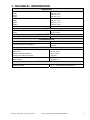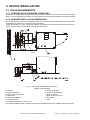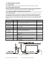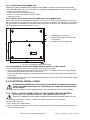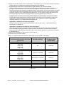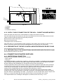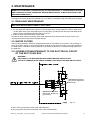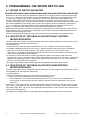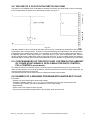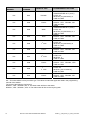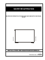
1
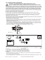
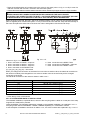
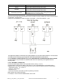
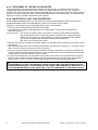
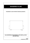
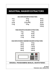
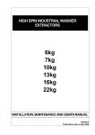
WATER RECUPERATION WATER RECUPERATION FOR WASHING MACHINE WITH ONE DRAIN VALVE INSTALLATION AND MAINTENANCE MANUAL 100657 A Publication date: 15 Aug 2012 1. TABLE OF CONTENTS 1. TABLE OF CONTENTS ................................................................................................ 1 2. IMPORTANT SAFETY INSTRUCTIONS....................................................................... 2 2.1. DURING TRANSPORTATION AND STORAGE .....................................................................................2 3. TECHNICAL INFORMATION ........................................................................................ 3 4. DEVICE INSTALLATION .............................................................................................. 4 4.1. SPACE REQUIREMENTS.......................................................................................................................4 4.1.1. REQUIRED DEVICE WORKING CONDITIONS ..............................................................................4 4.1.2. REQUIRED INSTALLATION DIMENSIONS.....................................................................................4 4.2. DEVICE INSTALLATION .........................................................................................................................5 4.2.1. UNPACKING .....................................................................................................................................5 4.2.2. POSITIONING THE DEVICE ............................................................................................................5 4.2.2.1. HEIGHT ALIGNMENT OF THE WATER RECYCLING SYSTEM .............................................5 4.2.2.2. INSTALLATION ON RUBBER FEET.........................................................................................6 4.2.2.3. INSTALLATION WITH FIXATION SCREWS (WITHOUT RUBBER FEET) ..............................6 4.2.2.4. MECHANICAL COUPLING BETWEEN WASHER AND RECYCLING SYSTEM .....................6 4.3. ELECTRICAL INSTALLATION ................................................................................................................6 4.3.1. SUPPLY CABLE CONNECTION FOR THE CABINET WASHER MODELS ...................................6 4.3.2. SUPPLY CABLE CONNECTION FOR THE NON – CABINET WASHER MODELS .......................8 4.3.3. PREPARATION OF THE EASY CONTROL MICROPROCESSOR FOR RECYCLING .........................8 4.3.4. PREPARATION OF THE GRAPHITRONIC MICROPROCESSOR FOR RECYCLING .......................8 4.4. CONNECTION OF WATER SUPPLIES ..................................................................................................8 4.4.1. WATER DRAIN CONNECTION........................................................................................................8 4.4.2. INTAKE OF RECYCLED WATER ....................................................................................................9 4.4.2.1. INTERNAL CONNECTION FOR ALL WASHERS EXCEPT WITH STAINLESS STEEL SOAP HOPPER ..9 4.4.2.2. ALTERNATIVE WAYS OF INSTALLATION ............................................................................10 4.4.2.3. INTERNAL CONNECTION FOR 22 kg / 50 lbs WASHERS WITH STAINLESS STEEL SOAP HOPPER..11 4.4.2.4. EXTERNAL CONNECTION .....................................................................................................11 4.4.3. TREATMENT OF THE RECYCLED WATER .................................................................................12 4.4.4. WATER RECYCLING TANK PROPERTIES ..................................................................................12 5. MAINTENANCE .......................................................................................................... 13 5.1. REGULARY MAINTENANCE................................................................................................................13 5.2. WATER FILTERS ..................................................................................................................................13 5.3. SCHEME FOR MAINTENANCE TO THE ELECTRICAL CIRCUIT OF THE RECYCLING BOX .........13 6. PROGRAMMING THE WATER RECYCLING............................................................. 14 6.1. INTAKE OF RECYCLING WATER........................................................................................................14 6.2. SELECTION OF THE DRAN VALVE WITH EASY CONTROL MICROPROCESSOR ........................14 6.3. SELECTION OF THE DRAN VALVE WITH GRAPHITRONIC MICROPROCESSOR .........................14 6.4. THE USE OF A FLOAT IN THE RECYCLING TANK............................................................................15 6.5. CONCEQUENCES OF THE RECYCLING SYSTEM ON THE AMOUNT OF LIQUID SOAP SIGNALS, APPLICABLE FOR EASY CONTROL, FULL CONTROL (GREEN BOARD) .......................................15 6.6. EXAMPLE OF A WASHING PROGRAM WITH WATER RECYCLING ................................................15 100657_A_PUB_DATE_15_AUG_2012.DOC INSTALLATION AND MAINTENANCE MANUAL 1 2. IMPORTANT SAFETY INSTRUCTIONS WARNING - SAVE THESE INSTRUCTIONS FOR LATER USE. Failure to comply with the instructions may lead to incorrect use of the appliance, and may result in risk of fire, bodily injuries or death and/or damage to the laundry and/or the appliance. WARNING - read the IMPORTANT SAFETY INSTRUCTIONS in this manual carefully before operating the appliance. Improper use of the appliance may cause risk of fire, electrical shock or serious body injuries or death as well as serious damage to the appliance. – This English version is the original. Without this version, the instructions are incomplete. – Before installation, operation and maintenance of the machine read carefully the complete instructions, i.e. „Installation, maintenance and user's manual“, „Programming manual“ and „Spare parts manual“. The Programming manual and Spare parts manual are not delivered with a machine by default. You shall ask the supplier / manufacturer to obtain Programming manual and Spare parts manual. – Follow the instruction written in manuals and keep the manuals in a proper place by the machine for later use. – If any problems or failures occur which you do not understand, immediately contact your dealer, serviceman or manufacturer. – Follow all basic and valid safety instructions and laws. Do not bypass the instructions stated in the instruction manual, and warnings on the labels. The labels must stay on the machine and they must be legible. – The device must be connected to the power and ground supply according to the Installation Manual and in compliance with the local standards, and done by a person with proper authorization. – The supplier or manufacturer must approve any changes concerning the installation that are not described in this Installation Manual. Otherwise, the supplier and manufacturer are not responsible for potential injuries to operators or for any damages. Interventions into the device execution or functions are not allowed, and the manufacturer refuses any responsibility in such cases. – Define the dangerous areas in the laundry room and obstruct an admission to them during machine's operating. – Operation of the device with malfunctions, missing parts or open covers is not allowed. – Make sure people can not reach any limbs into the drain outlets. – Do not store flammable materials around the device. – Keep the top of the device clean, without the presence of flammable materials. Do not wash or spray the device with running water. – Regularly once a three months check the proper function of ground. – Disconnect the power supply to the washer or device before doing any interventions to the device. – Do not repair when the device is in operation, disconnect the washing machine for repair or maintenance. Do not repair or replace any part of the water recycling system, or attempt any servicing unless specifically recommended in the maintenance instructions. All other servicing should be referred to a qualified service person. – The instructions and warnings described in this manual do not include all conditions and situations which may occur during the installation, maintain or operate of your device. They must be generally understood. Caution and care are factors which are not included in the design of this device and all persons who install, operate or maintain the machine must be qualified and familiar with the operating instructions. INSTALLATION AND SERVICE CAN BE DONE ONLY BY A SERVICE ORGANIZATION WITH PROPER AUTHORIZATION. 2.1. DURING TRANSPORTATION AND STORAGE If the customer provides transportation or storage, it is necessary to follow the manufacturers instructions concerning transportation, handling and storage. In this case the manufacturer is not responsible for any damage of the device during transportation.The device is packed in a double layered cardboard box before transport. Instructions concerning transportation, handling and storage: – When stored in a free area the device must be protected against mechanical damage and weather condition effects. – The device must be stored with the topside upward and may not be placed on its side. – No more than 4 recycling systems may be piled up on top of each other for safety reasons. – The maximum weight that may be piled on top of a recycling system is 50 kg / 110 lbs. – Avoid severe climatic conditions and excessive humidity. When the temperature changes and this causes damp, you must avoid water under and around the machine and also on his covers. – Do not spray water directly on the device. 2 INSTALLATION AND MAINTENANCE MANUAL 100657_A_PUB_DATE_15_AUG_2012.DOC 3. TECHNICAL INFORMATION DIMENSIONS PACKING DIMENSIONS: Width: Depth: Height: DEVICE DIMENSIONS: Width: Depth: Height: Minimum distance between wall and washer 500 mm / 19,7“ 400 mm / 15,7“ 300 mm / 11,8“ 370 mm / 14,6“ 365 mm / 14,4“ 270 mm / 10,6“ 900 mm / 35,4“ WEIGHT Net Gross 14 kg / 31 lbs. 16 kg / 35 lbs. DEVICE EXECUTION Recycling box: Stainless steel / Galvanized steel ELETRICAL DATA Electrical system of the device: Permitted deviation of voltage: Permitted deviation of frequency: 1x 208 – 240V AC 50/60Hz 10% of nominal voltage 1% Hz CONNECTION WATER CONNECTION: Water inlet: Maximal water temperature: Average flow rate of one valve: CONNECTION OF WATER DRAINAGE: Water outlets: 75 mm / 2,95“ 90°C / 194°F 180 l/min 76.2 mm / 3“ WORKING CONDITIONS Ambient temperature Relative humidity From + 5 ° C (41°F) to + 45 °C (113°F) 30 % – 90 % without condensation Tab. 3 100657_A_PUB_DATE_15_AUG_2012.DOC INSTALLATION AND MAINTENANCE MANUAL 3 4. DEVICE INSTALLATION 4.1. SPACE REQUIREMENTS 4.1.1. REQUIRED DEVICE WORKING CONDITIONS The device is not designed to be placed in an environment where it can come into contact with spraying water. Do not install the device where it can be subject to environmental conditions or extreme humidity. 4.1.2. REQUIRED INSTALLATION DIMENSIONS If the requirements in respect to installation dimensions are not met, the manufacturer can not be held responsible for problems in connection with accessibility. Leave at least a 0,9 m / 35,4“ free space between the rear panel of the washer and the wall. Above the device, there must be free space for the maintenance access. Fig. 4.1.2.A. Required installation dimensions A. Washer B. Recycling system C. Inlet of recycling system D. Drain hose E. Outlet of the washer F. Protection plate Indexes on figure above: G. Outlet to sewage H. Outlet to recycling tank I. Drain to sewer J. Drain to recycling tank K. Drain pipe L. Wall X1: Minimum distance of 120 mm / 4,7“ X2: Distance between drain channels or pipes must be determined by the installer of the drain system 4 INSTALLATION AND MAINTENANCE MANUAL 100657_A_PUB_DATE_15_AUG_2012.DOC 4.2. DEVICE INSTALLATION 4.2.1. UNPACKING After unpacking, check if the device hasn’t been damaged and if all the accessories are included. 4.2.2. POSITIONING THE DEVICE The water recycling system has to be placed in such a way that the centerline of the outlet of the washing machine coincides with the centerline of the inlet of the water recycling device, as shown in figure above. The manufacturer is not responsible for consequences caused by a wrong installation. 4.2.2.1. HEIGHT ALIGNMENT OF THE WATER RECYCLING SYSTEM Put two retaining clips over the rubber hose and place the rubber hose over the outlet of the washer and the inlet of the recycling system. You can position the water recycling system in several ways depending on the type of washing machine where the water recycling system has to be connected to. The first way is to position the machine only on his 4 adjustable rubber feet on the ground or on an elevation. The second way is to fasten the device directly on the ground or on an elevation without the rubber feet. In table 4.2.2.1, the manufacturer gives the way of installation for all types of washers. The height mentioned in the table is shown in the figure under the table. WASHERS HEIGHT Rigid mounted: 6 kg / 15 lb, 7 kg / 18 lb, 10 kg / 25 lb 13 kg / 30 lb 18 kg / 40 lb, 22 kg / 50 lb 27 kg / 60 lb Free standing: 6 kg / 15 lb, 7 kg / 18 lb, 10 kg / 25 lb 135 13 kg / 30 lb 60 16 kg / 35 lb 55 22 kg / 55 lb 195 INSTALLATION ELEVATION 92 Adjust the height of the rubber feet - 86 - 90 Adjust the height of the rubber feet Place the recycling system with the rubber feet on a elevation Adjust the height of the rubber feet 78 Adjust the height of the rubber feet Remove the rubber feet and use anchore box to the ground Remove the rubber feet and use anchore box to the ground Place the recycling system with the rubber feet on a elevation 55 mm / 2,2“ - 115 mm / 4,5“ Non – cabinet: 22 kg / 55 lb 173 Place the recycling system with the rubber feet on a elevation 90 mm / 3,5“ Tab. 4.2.2.1. Fig. 4.2.2.1. Height alignment 100657_A_PUB_DATE_15_AUG_2012.DOC INSTALLATION AND MAINTENANCE MANUAL 5 4.2.2.2. INSTALLATION ON RUBBER FEET THE RECYCLING SYSTEM WILL BE FIRMLY POSITIONED TO THE FLOOR OR ELEVATION AND MUST RELIABLY REST IN ALL FOUR FEET OF THE DEVICE AND MUST BE PLACED WATER – LEVEL! In order to adjust the rubber feet: – Loosen the locknut above the rubber foot – Screw or unscrew the foot to the desired position – Tighten the locknut 4.2.2.3. INSTALLATION WITH FIXATION SCREWS (WITHOUT RUBBER FEET) Remove the rubber feet and disassemble the rear and top cover. Fasten the ground plate to the ground or the elevation by means of minimum two bolts or screws that can be placed in the free holes on each side of the ground plate. The installer can choose the type of connection to the floor. The manufacturer advises a bolt or screw with a minimum diameter of 4 mm. 1. Ground plate of the device 2. Holes for fastening the ground plate to the ground 3. Welded nuts for the rubber feet Fig. 4.2.2.3. Installation with fixation screws 4.2.2.4. MECHANICAL COUPLING BETWEEN WASHER AND RECYCLING SYSTEM – Unscrew the bolts that fasten the white plastic drain outlet of the washer. – Place the protection plate over the drain outlet of the washer. And fasten it to the frame of the washing machine with the bolts that you have just unscrewed. – Fasten the other side of the protection plate to the side plate of the recycling system with two M6 bolts and washers. – Finally tighten the hose clips, which are placed over the rubber hose on the outlet of the washing machine and the inlet of the device. 4.3. ELECTRICAL INSTALLATION AUTHORIZED WORKERS WITH A VALID QUALIFICATION IN ACCORDANCE WITH VALID LOCAL STANDARDS MUST EXECUTE THE ELECTRICAL CONNECTION AND EARTHING OF THE DEVICE. The water recycling system has been designed for connecting to the electrical network of the washer. 4.3.1. SUPPLY CABLE CONNECTION FOR THE CABINET WASHER MODELS DISCONNECT THE WASHING MACHINE POWER BEFORE INSTALLATION. THE INLET TERMINALS ARE UNDER CURRENT EVEN WHEN THE MAIN SWITCH IS OFF. Use the supplied cable (3 x 0.75 mm² + earth) with copper conductors for the connection. The way how to proceed: 1. Open the top cover of the washer. 2. Remove the plastic black plug in the rear panel. The black plug is positioned near the turnbuckle for the main power supply cable. 6 INSTALLATION AND MAINTENANCE MANUAL 100657_A_PUB_DATE_15_AUG_2012.DOC 3. Mount a turnbuckle, following the local standards, in the appearing hole. If the hole is already occupied by another cable, then install a third turnbuckle following the local standards. 4. a) Applicable for Full Control microprocessor (green board), see electrical scheme: Put the cable through the turnbuckle and connect the cables to the terminal as shown in the fig. 4.3.1. (the figure is just an example). The connection of the black and brown wire is shown in table 4.3.1. The black and brown wire are always connected together on the terminal. The blue wire must be connected to the terminal with common potential to which grey wire is already connected. Connect a green-yellow protection conductor to the equipotential bonding terminal. The wire must be fixed to the washer, thus securing the cable mechanically and against water by means of tightening the turnbuckle. b) Applicable for microprocessors Easy Control, Graphitronic (blue board), see electrical scheme: Put the cable through the turnbuckle. Connect a blue wire to the terminal A2 of the frequency inverter CFI contactor (the common potential of the control voltage - grey conductors). Connect a green-yellow protection conductor to the equipotential bonding terminal. Applicable for machines with white soap hopper: Connect a brown conductor to the microprocessor by means of the contact - (code PRI350040044) to connector R - (position 10). Applicable for machines with stainless steel soap hopper: To control the drain valves the machine has to be equipped with extension relay board (code 520139), that is connected to the microprocessor by means of cable - (code 520187). Connect a brown conductor to the terminal E1 of the extension relay board. (The control voltage - potential nr.45 has to be connected to the terminal E10). 5. Make sure the wires are not able to move in the wiring box. 6. Close the top cover of the washer. Table 4.3.1. shows the electrical connection of the water recycling system to the washer. WASHING MACHINES microprocessor Easy Control, Full Control (green board) Rigid mounted 6 kg / 15 lb, 7 kg / 18 lb, 10 kg / 25 lb, 16 kg / 35 lb, 22 kg / 50 lb Free standing 6 kg / 15 lb, 7 kg / 18 lb, 10 k g/ 25 lb, 16 kg / 35 lb 6 kg / 15 lb, 7 kg / 18 lb, 10 kg / 25 lb 16 kg / 35 lb 22 kg /50 lb with stainless steel soap hopper 22 kg /50 lb with white soap hopper Non – cabinet 22 kg / 50 lb 22 kg / 50 lb MOTOR CONTROL CONNECTION FOR THE BLACK AND BROWN WIRE All terminal 6 Frequency controlled terminal 8 Not frequency controlled terminal 4 All Frequency controlled terminal 11 terminal 8 Not frequency controlled Frequency controlled terminal 11 terminal 10 Tab. 4.3.1. 100657_A_PUB_DATE_15_AUG_2012.DOC INSTALLATION AND MAINTENANCE MANUAL 7 Fig. 4.3.1. 1. Terminal 2. Bushing 3. Clamp 4. Terminal for earthing 4.3.2. SUPPLY CABLE CONNECTION FOR THE NON – CABINET WASHER MODELS Follow the same instructions as for cabinet washers, except for the actual connection: Push the cable through the turnbuckle on the side of the washer and connect the cables with the terminal inside the machine (directly beside the turnbuckle) as follows: Black and brown wire to terminal X10.8 Blue wire to terminal X10.9 Yellow/green wire to terminal X10.10 After these steps, it is recommended to make a sagging on the cable in front of its entry on the recycling system. In this way ingress of the running condensed water into recycling box can be avoided. 4.3.3. PREPARATION OF THE EASY CONTROL MICROPROCESSOR FOR RECYCLING See Programming manual „Easy Control“. 4.3.4. PREPARATION OF THE GRAPHITRONIC MICROPROCESSOR FOR RECYCLING See Programming manual „Full Control“. 4.4. CONNECTION OF WATER SUPPLIES 4.4.1. WATER DRAIN CONNECTION The drain can be executed in several ways, for example: – Drain channel – Drain pipe ALL DRAIN CHANNELS / PIPES HAVE TO BE DE – AERATED IN ORDER TO ASSURE GOOD DRAINING. THE CHANNEL / PIPE MUST BE LOCATED LOWER THAN THE OUTLETS OF THE RECYCLING BOX. DO NOT REDUCE THE DIAMETER OF THE WATER OUTLETS ON THE DEVICE. The drain pipe/drain channel must have the capacity to be able to handle the total output of all connected machines. Every time a machine is coupled on the drainpipe, the diameter of the tube or the width of the waste channel must be larger. The drain channel or pipe must have a minimum section of 35 cm² / 5,4 square inch per installed washer that is connected to this drain pipe or channel. The drains are situated on the rear of the recycling box. One drain has to be connected to the waste channel or pipe. This is the lowest drain on the rear of the device. The highest drain must be connected to the drain channel or pipe leading to the water – recycling tank. You can use the elbow, which is a part of the delivery, to connect the outlets with the drain channel or pipe. Secure the elbow with a clamp. The required distances for installing the drainpipes or channels can be found in fig. 4.1.2.A 8 INSTALLATION AND MAINTENANCE MANUAL 100657_A_PUB_DATE_15_AUG_2012.DOC 4.4.2. INTAKE OF RECYCLED WATER DISCONNECT THE WASHING MACHINE POWER BEFORE INSTALLATION. THE INLET TERMINALS ARE UNDER CURRENT EVEN WHEN THE MAIN SWITCH IS OFF. 4.4.2.1. INTERNAL CONNECTION FOR ALL WASHERS EXCEPT WITH STAINLESS STEEL SOAP HOPPER The following explanation is only valid if an existing washer, bought without the option „water recycling“, has to be converted in order to connect a recycling device to that washer. The installation described hereafter will also be the standard installation for washers if the option „water recycling“ is ordered by the customer. When you order a washer with the option „water recycling“, you need to choose one of the following systems: A. Cold soft / Cold hard water system / Recycling water B. Cold soft / Hot soft water system / Recycling water Cold hard water can not be used in combination with the recycling system when hot water is used. To have a proper inlet valve function, keep the suitable water pressure according to the values stated in technical data of the washer. Too low pressure can cause prolongation of the washing cycle and / or malfunctions of valves and machine. The following steps have to be taken for the standard installation (recycling water used only for prewash; for alternative ways of installation, see next paragraph): – Remove the top cover of the washer. – Remove all the water inlet valves and the brass T – piece if it is mounted on the inside of the rear panel. – Place the 2 – way – valve for warm water, that you have just removed from the lowest position, in the highest position. See fig. 4.4.2.1.B. – Turn the lowest and the highest coil of the 3 – way water valve, if not done yet, 45°, as shown in the fig. 4.4.2.1.A. Lift the coil a few millimeters from the plastic valve itself, by means of a screwdriver, and turn the coil 45° manually. Then push the coil down by clicking it between two pins. – Mount the two supplied 3 – way valves in the lowest positions. See fig. 4.4.2.1.B. Fig. 4.4.2.1.A. Fig. 4.4.2.1.B. 1. Water valve (2 – way) for the warm water supply (highest position) 2. Water valve (3 – way) for the cold soft water supply (middle position) 3. Water valve (3 – way) for the recycling water supply (lowest position) 4. Air vent – Remove the stickers next to valves 1 and 3 (see fig. 4.4.2.1.B) in case of a cold soft / hot soft and cold soft / cold hard / hot soft water system. – Place the supplied sticker of recycled water next to the valve for water recycling (valve 3 in fig. 4.4.2.1.B). 100657_A_PUB_DATE_15_AUG_2012.DOC INSTALLATION AND MAINTENANCE MANUAL 9 – Place the supplied sticker of hot water next to the valve for hot water (valve 1 in fig. 4.4.2.1.B) in case of a cold soft / hot soft and cold soft / cold hard / hot soft water system. – Connect the hoses inside the washer between the water valves and the soap hopper as shown in figure hereafter. ! WARNING ! NEVER CHANGE THE CONNECTION BETWEEN THE HOSES AND THE SOAP HOPPER EXCEPTION: THE HOSE ATTACHED TO INLET 7 (ON FIGURE HEREAFTER), IF PRESENT (IN CASE OF WASHER WITH COLD HARD/COLD SOFT/HOT SOFT WATER), MUST BE REMOVED. When the hose is removed, the inlet 7 has to be closed as follows: Cut off a piece of the removed hose and place a supplied piece of brass shaft (diam. 12 mm) in the hose and fix it with the clamp that was already on the hose. Now place the other side of the hose over inlet 7 and tighten it with the second clamp. Fig. 4.4.2.1.C. Indexes on fig. 4.4.2.1.C. 1. Hose connection to RINSE – soap box 2. Hose connection to WASH – soap box 3. Hose connection to WASH – soap box 4. Hose connection to the DIRECT inlet (I1), (I2), (I3), (I4), (I5), (I6) – inlet valves 5. Hose connection to the DIRECT inlet 6. Hose connection to PREWASH – soap box 7. Hose connection to the DIRECT inlet When you change the connection of the hoses from one valve to another valve, the electrical connection to the valves must always be changed from one valve to another valve in the same way as the changed connection of the hoses. The electrical connection to the valves is shown in table 4.4.2.1. VALVE (SEE FIG. 4.4.2.1.C) (I1) (I2) (I3) (I4) (I5) (I6) ELECTRICAL WIRE CONNECTION Wire N° 30 + common (gray) Wire N° 32 + common (gray) Wire N° 20 + common (gray) Wire N° 42 + common (gray) Wire N° 35 + common (gray) Wire N° 46 + common (gray) Tab. 4.4.2.1. – Close the top cover of the washer. 4.4.2.2. ALTERNATIVE WAYS OF INSTALLATION The standard installation, explained above, sees to it that recycling water is taken in via the part of the soap hopper that is reserved for prewash. Other possibilities. The following explanation is based on the standard installation, as explained in 4.4.2.1: Recycling water used for PREWASH / WASH / RINSES separately or a combination of these. A few examples of installation are shown in table 4.4.2.2., the valve numbers are explained in fig. 4.4.2.1.C. 10 INSTALLATION AND MAINTENANCE MANUAL 100657_A_PUB_DATE_15_AUG_2012.DOC RECYCLED WATER USED FOR: WAY OF INSTALLATION Switch (I5) and (I2) by switching the hose connection to the WASH valves and the electrical wiring to the valves. Switch (I6) and (I2) by switching the hose connection to the RINSES valves and the electrical wiring to the valves. Place (I5) next to (I2) on the valve for water recycling by PREWASH and WASH changing the hose connection and the wiring from (I2) to an available place on the recycling valve. Tab. 4.4.2.2. Only (I2), (I5) and (I6) can be switched to the valve for water recycling. At least one of them must be placed on the water – recycling valve. Example of the installation for water recycling in the WASH – cycle and the RINSE – cycle: Fig. 4.4.2.2.A THE MANUFACTURER CAN NOT BE HELD RESPONSIBLE FOR THE MALFUNCTIONING OF THE WASHER IF OTHER VALVES THAN (I2), (I5) OR (I6) ARE USED FOR WATER RECYCLING VALVE. 4.4.2.3. INTERNAL CONNECTION FOR 22 kg / 50 lbs WASHERS WITH STAINLESS STEEL SOAP HOPPER On these washers, only the sticker for cold hard water has to be replaced by the supplied sticker for recycling water. 4.4.2.4. EXTERNAL CONNECTION Connect the water supply hoses to the right water valves, see fig. 4.4.2.1.B. Connect supply of the recycling water, to the inlet (G ¾“) for recuperated water on the washer with a supplied hose. If you want to use another hose, then use one with the following minimum requirements: – Temperature range: -10° C to 90° C – Pressure: 8 bar/116 psi – Connector: G ¾“ – Hose and connector must resist corrosion by washing chemicals Better qualities are always admissible. For example, a hose in eminent EPDM rubber can be used. 100657_A_PUB_DATE_15_AUG_2012.DOC INSTALLATION AND MAINTENANCE MANUAL 11 4.4.3. TREATMENT OF THE RECYCLED WATER The recycled water must be filtered before entering the recycling tank. A mechanical filter should be installed which filters particles (fluff, buttons, paper, etc.) with a maximum size of 0,2 mm or bigger. A smaller width of the mesh of the filter is always advisable. There must also be a filter at the pressure side of the pump. It is also possible to install a chemical filter additional to the mechanical filter. The manufacturer advises to consult an installer specialized in filter systems. 4.4.4. WATER RECYCLING TANK PROPERTIES AUTHORIZED WORKERS WITH A VALID QUALIFICATION IN ACCORDANCE WITH VALID LOCAL STANDARDS MUST EXECUTE THE INSTALLATION OF THE RECYCLING TANK. The water – recycling tank must meet the following minimum requirements: The tank must be made following the national standards. Tank capacity: the capacity varies depending on multiple factors, so it must be calculated by an authorized engineer. The factors are: – the number of washing steps, per washer, in which the water will be recuperated – the programmable amount of water that will be recuperated in a washing step (this – amount can be looked up in the installation or programming manual of the washer) – the number of washers that will deliver water to the recycling tank – the use of recycled water per washer The tank must have an overflow to the sewer. Water from the sewer may not be able to flow back into the recycling tank. The network of pipes and hoses, the water pump and the recycling tank must be non – corroding. It must resist corrosion of water and chemicals used for washing. The tank must be equipped with a system that fills the tank with clean water to a minimum working level, in case the water level drops below a minimum. If this requirement is not met, the washer will not function properly when no recycling water is fed to the washer. A pump must transport the recycling water from the tank to the washer. The requirements for the pump depend on the number and type of washers that are connected to the recycling system. The maximum pump pressure is 8 bar / 116 psi. An authorized engineer must calculate the pump properties. ! WARNING ! IT IS PROHIBITED TO HEAT THE WATER IN THE RECYCLING TANK. THIS WOULD DISTURB THE TEMPERATURE BALANS OF THE WASHER AND WILL MAKE THE REMAINING CHEMICALS IN THE RECYCLING WATER MORE ACTIVE, WHICH WILL AID THE CORROSION OF THE INSTALLATION. 12 INSTALLATION AND MAINTENANCE MANUAL 100657_A_PUB_DATE_15_AUG_2012.DOC 5. MAINTENANCE ! WARNING ! ALWAYS FOLLOW SAFETY INSTRUCTIONS! ANY INTERFERENCE TO THE MACHINE FUNCTIONS AND CONSTRUCTION ARE PROHIBITED. BEFORE MAINTENANCE, ALWAYS DISCONNECT THE MACHINE POWER SUPPLY. In case of serious failures call the technical service of your supplier. When replacing any parts of the device, exchange them with original parts obtained from your dealer or ordered through the spare parts catalogue. 5.1. REGULARY MAINTENANCE ! WARNING ! HOT PARTS SHOULD BE ALLOWED TO COOL FIRST ! 1. Check visually if the drain valves, hoses and connections are not leaking during the wash process. 2. It is also important that the valve opens or closes properly after working. Make sure that no water flows out the water valve to the sewer during the recycling step, by feeling at the drain hose that leads to the sewer. Contact a qualified technician when this occurs. 3. Clean the drain if the water doesn’t drain fluent. Remark: the drain valve to the sewer opens when electrical power falls out and the drain valve to the recycling tank closes when electrical power falls out. 5.2. WATER FILTERS The recycling installation should be equipped with a filter by the installer of the system. It is necessary to clean up the filter regulary to avoid a prolongation of filling the machine with water or the malfunctioning of the water valves. Intervals of cleaning depend on the quality of the water, for example foreign particles in the water line. 5.3. SCHEME FOR MAINTENANCE TO THE ELECTRICAL CIRCUIT OF THE RECYCLING BOX WARNING ! DISCONNECT THE WASHING MACHINE POWER BEFORE INSTALLATION. THE INLET TERMINALS ARE UNDER CURRENT EVEN WHEN THE MAIN SWITCH IS OFF. Applicable for microprocessor: Easy Control, Graphitronic (blue board) Applicable for microprocessor: Easy Control, Graphitronic (green board) Fig. 5.3. A. Drain valve (normal open), order code: PRI340045051 B. Recycling drain valve (normal closed), order code: PRI340047051 100657_A_PUB_DATE_15_AUG_2012.DOC INSTALLATION AND MAINTENANCE MANUAL 13 6. PROGRAMMING THE WATER RECYCLING 6.1. INTAKE OF RECYCLING WATER MACHINES WITH WHITE SOAP HOPPER AND MACHINES WITH STAINLESS STEEL SOAP HOPPER Depending on the hose connection, between the water valve for recycling water and the soap hopper (see fig. 4.4.2.1.C), that you have executed, you can now decide which valve has to be selected in the program in order to use recycling water. Keep in mind that the choice of the water valve is also related to the transport of the washing powder from the soap hopper into the washer. For selecting water recycling, choose the inlets ((I2), (I5) or / and (I6)) that are installed on the water valve for water recycling. When using the standard installation of the factory, then (I2) has to be programmed in the PREWASH – step (see fig. 4.4.2.1.C.). Make sure that there is always a valve selected that flushes the washing powder into the washer. The selected valve will depend on the programmed temperature in the step. When liquid soap is used in a program step that uses recycled water, then make sure that a water valve is selected with a direct connection to the soap hopper. Which valve that has to be selected depends on the programmed temperature in the step. The way of programming washing programs can be found in the programming manual of the washer. 6.2. SELECTION OF THE DRAN VALVE WITH EASY CONTROL MICROPROCESSOR The step, which will be used to recuperate the drain water from, must be programmed. Drain water can only be recuperated in a drain step and extract step. Proceed as follows: The second drain valve can only be programmed by the PC – Network Communication Software. It‘s possible to disable this function even if the PC – Network Communication Software is not available. – When d2 = oFF, at all the drain sequences, the water will be drained by the first Drain valve. – When d2 = on, the water will be drained by the second drain valve, for those sequences that the second drain valve was selected by the PC software. In the drain or extract step, drain 2 must be programmed in order to let the drain water flow to the recycling tank. If drain 1 is programmed, the drain water will flow to the sewer. On the 22kg – washers with stainless steel soap hopper, drain 1 and 2 can be programmed at the same time. In this case the water will flow to the sewer and the recycling tank. For programming or editing a drain or extract step, see the programming manual for „Easy Control“. 6.3. SELECTION OF THE DRAN VALVE WITH GRAPHITRONIC MICROPROCESSOR The step, which will be used to recuperate the drain water from, must be programmed. Drain water can only be recuperated in a drain step and extract step. Proceed as follows: Select the configuration menu and put the following parameters on „yes“: – Drain valve 2: this enables the timer to choose the recycling valve. – Check signal recycle: this parameter should only be put on „yes“, when a float is installed in the recycling tank. The float switch must give a signal to the timer when the water level is too low. See chapter 5.3. In the drain or extract step, drain 2 must be programmed in order to let the drain water flow to the recycling tank. If drain 1 is programmed, the drain water will flow to the sewer. On the 22kg – washers with stainless steel soap hopper, drain 1 and 2 can be programmed at the same time. In this case the water will flow to the sewer and the recycling tank. For programming or editing a drain or extract step, see the programming manual for timer „Full Control“. 14 INSTALLATION AND MAINTENANCE MANUAL 100657_A_PUB_DATE_15_AUG_2012.DOC 6.4. THE USE OF A FLOAT IN THE RECYCLING TANK This option is not obligated, but it is advisable to install a level switch.This level switch must be connected to the microprocessor by means of a potential-free contact. See fig. 6.5. Fig. 6.4. The relay contact k1 has to close when the water level is too low. Terminal B is positioned on the left side, at the bottom of the microprocessor. Terminal A is positioned directly above terminal B. The microprocessor is positioned on the inside of the washer, more precisely on the inside of the front panel (the other side of the display). When the „Check signal recycle“ – parameter is put on „yes“ in the configuration menu, the timer will give a signal when the water level of the recycling tank is too low. In case of a 22kg washer with stainless steel soap hopper, the timer will choose an other water inlet in order to assure the right functioning of the washer. 6.5. CONCEQUENCES OF THE RECYCLING SYSTEM ON THE AMOUNT OF LIQUID SOAP SIGNALS, APPLICABLE FOR EASY CONTROL, FULL CONTROL (GREEN BOARD) As a result of the use of a terminal, which is normally used for a liquid soap pump, for the control of the water recycling system, it is no longer possible to use this terminal for the control of a liquid soap pump. So one less liquid soap pump can be used. The restricted terminal can be determined in the electrical scheme of the washer. 6.6. EXAMPLE OF A WASHING PROGRAM WITH WATER RECYCLING Information: – Washer with white soap hopper (white soap hopper) – Standard installation (see fig. 4.4.2.1.C.): (I2) is connected on the recycling valve and the hose connection lays between (I2) and the prewash box on the soap hopper. – Requirements: – Water of the second rinse must be recycled – Use as much as possible recycled water in the prewash, wash and first rinse. 100657_A_PUB_DATE_15_AUG_2012.DOC INSTALLATION AND MAINTENANCE MANUAL 15 PROCESS NUMBER STEP NUMBER NAME OF STEP P01 St01 Prewash P01 St02 Extract P01 St03 Wash P01 St04 Drain P01 St05 1 rinse st P01 St06 Extract P01 St07 2 rinse P01 St08 Extract P01 St09 3 rinse P01 St10 Extract nd rd PROGRAMMER FUNCTIONS PREWASH TEMPERATURE 40°C (104°F) LEVEL XX INLETS 2 (recycled water), 3 TIME 04.0 MIN EXTRACT DRAIN1: „YES“ , DRAIN2: „NO“ TIME 00.5 MIN WASH TEMPERATURE 60°C (140°F) LEVEL XX INLETS 2 (recycled water), 3, 4 TIME 09.0 MIN DRAIN DRAIN1: „YES“ , DRAIN2: „NO“ TIME 00.5 MIN RINSE LEVEL XX INLETS 2 (recycled water), 6 TIME 01.5 MIN EXTRACT DRAIN1: „YES“ , DRAIN2: „NO“ TIME 00.5 MIN RINSE LEWEL XX INLETS 6, 5 TIME 01.5 MIN EXTRACT DRAIN1: „YES“ , DRAIN2: „YES“ TIME 00.5 MIN RINSE LEVEL XX INLETS 1 [use of softener] TIME 02.0 MIN EXTRACT DRAIN1: „YES“ , DRAIN2: „NO“ TIME 04.5 MIN Tab. 6.6. XX – This value differs in every machine type. The values for individual types are listed in the programming manual of the washer. The result of the following choices are: DRAIN1: „YES“ , DRAIN2: „NO“ The drain water will flow to the sewer. DRAIN1: „YES“ , DRAIN2: „YES“ The drain water will flow to the recycling tank. 16 INSTALLATION AND MAINTENANCE MANUAL 100657_A_PUB_DATE_15_AUG_2012.DOC IMPORTANT ! MACHINE TYPE: PROGRAMMER: -ELECTRONIC TIMER „Easy Control“ „Graphitronic“ INSTALLATION DATE: INSTALLATION CARRIED OUT BY: SERIAL NUMBER: ELECTRICAL DETAILS: .............VOLT...............PHASE............HZ NOTE: ANY CONTACTS WITH YOUR DEALER REGARDING MACHINE SAFETY, OR SPARE PARTS, MUST INCLUDE THE ABOVE IDENTIFICATION. MAKE CERTAIN TO KEEP THIS MANUAL IN A SECURE PLACE FOR FUTURE REFERENCE. DEALER: