1
OPERATION MANUAL
VDL 6000 AIS Class A/Inland
CNSS-11-1893-J
MANUAL
Date
Classification
Page
2012-12-06
Unclassified
2 (85)
Document No.
Issue
CNSS-11-1893
J
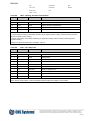
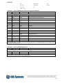
DOCUMENT CHANGE RECORD
Revision
Changes
Date
A
First issue
2011-12-21
B
Added chapter about how to enter symbols in alphanumeric text.
Table 1-1 is updated.
2012-03-22
C
Table 2-1 is updated.
2012-05-08
D
Added section Night mode.
Added save values and added information to backlight and Rx malfunction.
2012-05-10
E
Chapter 7.3.2, presentation of Ownship data updated
2012-05-21
F
Figure 5-1 is updated.
Table 2-1 is updated with antenna mechanical data.
2012-05-29
G
Added inland specific functional messages
2012-07-16
H
Added references [5] and [6]
2012-08-14
I
Moved configuration of ERI for AIS Inland to Set voyage data.
Clarified that no password is required for configuration of dimensions in AIS
Inland.
Fixed reference to section 7.2.4.2.
Configuration of ERI moved to section 7.5.1.
2012-08-15
J
Added section 7.5.9 and 7.5.10
Updated Table 8-28 with Long-range AIS broadcast channel 1 and 2
Added proprietary NMEA sentence GNSS
2012-12-06
Updated section 2 with FCC certification and GLONASS aspects
This document and attachments shall remain our property. They may not without our written consent, either
in their original state or with any changes, be copied or reproduced, disclosed to or delivered to anyone
unauthorized nor used for other purposes than what has been confirmed by C.N.S. Systems AB in writing.
BL0119C
MANUAL
Date
Classification
Page
2012-12-06
Unclassified
3 (85)
Document No.
Issue
CNSS-11-1893
J
TABLE OF CONTENTS
1
SCOPE .................................................................................................................................................................. 6
1.1
1.2
1.3
2
REGULATORY NOTICE .......................................................................................................................................... 7
2.1
3
APPLICABLE STANDARDS AND REGULATIONS .................................................................................................................. 8
HOW TO USE THIS MANUAL ................................................................................................................................ 9
3.1
3.2
4
IDENTIFICATION ....................................................................................................................................................... 6
PURPOSE ................................................................................................................................................................ 6
AUDIENCE............................................................................................................................................................... 6
MANUAL OVERVIEW................................................................................................................................................. 9
ICONS .................................................................................................................................................................... 9
ABOUT AIS ......................................................................................................................................................... 10
4.1
BASICS ................................................................................................................................................................. 10
4.2
INFORMATION EXCHANGE ........................................................................................................................................ 10
4.3
SHIP INFORMATION ................................................................................................................................................ 11
4.3.1
Static Information ..................................................................................................................................... 11
4.3.2
Dynamic Information................................................................................................................................. 11
4.3.3
Voyage Related Information ..................................................................................................................... 12
5
INSTALLATION OVERVIEW ................................................................................................................................. 13
5.1
VDL 6000 TRANSPONDER FRONT PANEL DESCRIPTION................................................................................................. 14
5.1.1
Power Indicator LED .................................................................................................................................. 14
5.1.2
Blue sign (Inland only) ............................................................................................................................... 14
5.1.3
Tx Indicator LED ......................................................................................................................................... 14
5.1.4
Rx and DSC Indicator LED’s ........................................................................................................................ 14
5.1.5
Alarm Indicator LED................................................................................................................................... 14
6
INITIAL CONFIGURATION ................................................................................................................................... 15
7
USING THE VDL 6000 TRANSPONDER ................................................................................................................ 16
7.1
START THE VDL 6000 TRANSPONDER ........................................................................................................................ 16
7.2
MENU OVERVIEW .................................................................................................................................................. 17
7.2.1
Navigating the Menu ................................................................................................................................ 19
7.2.2
SHOW Menu .............................................................................................................................................. 20
7.2.3
SEND Menu................................................................................................................................................ 20
7.2.4
CONFIGURE Menu ..................................................................................................................................... 21
7.2.5
Alarm Popup .............................................................................................................................................. 22
7.3
SHOW ................................................................................................................................................................ 22
7.3.1
Alarms ....................................................................................................................................................... 22
7.3.2
Safety Messages ........................................................................................................................................ 24
7.3.3
Inland Messages (Inland only) ................................................................................................................... 26
7.3.4
Targets ...................................................................................................................................................... 27
7.3.5
OwnShip Data............................................................................................................................................ 31
7.3.6
Status Changes .......................................................................................................................................... 32
7.3.7
LR requests ................................................................................................................................................ 33
7.3.8
Regional Settings ....................................................................................................................................... 35
7.3.9
About AIS ................................................................................................................................................... 36
7.3.10 Event Log ................................................................................................................................................... 36
7.4
SEND .................................................................................................................................................................. 37
7.4.1
Inland Specific Messages (Inland only) ...................................................................................................... 37
This document and attachments shall remain our property. They may not without our written consent, either
in their original state or with any changes, be copied or reproduced, disclosed to or delivered to anyone
unauthorized nor used for other purposes than what has been confirmed by C.N.S. Systems AB in writing.
BL0119C
MANUAL
Date
Classification
Page
2012-12-06
Unclassified
4 (85)
Document No.
Issue
CNSS-11-1893
J
7.4.2
Addressed or Broadcast............................................................................................................................. 38
7.4.3
Send Addressed to Target ......................................................................................................................... 38
7.4.4
Send Addressed to MMSI........................................................................................................................... 38
7.4.5
Select Transmission Channel ..................................................................................................................... 38
7.4.6
Confirm Transmission ................................................................................................................................ 39
7.4.7
Send Status ................................................................................................................................................ 39
7.5
CONFIGURE ....................................................................................................................................................... 41
7.5.1
Voyage Related Data ................................................................................................................................. 42
7.5.2
Backlight Level ........................................................................................................................................... 45
7.5.3
Night mode ................................................................................................................................................ 45
7.5.4
Static Data ................................................................................................................................................. 45
7.5.5
Ship Dimensions ........................................................................................................................................ 47
7.5.6
Regional Settings ....................................................................................................................................... 49
7.5.7
LR reply mode ............................................................................................................................................ 51
7.5.8
Transmitter On/Off .................................................................................................................................... 51
7.5.9
Longrange Broadcast ................................................................................................................................ 51
7.5.10 GNSS Settings ............................................................................................................................................ 52
7.5.11 Passwords.................................................................................................................................................. 52
7.5.12 Serial Port Settings .................................................................................................................................... 52
7.5.13 Language ................................................................................................................................................... 53
8
NMEA REFERENCE MANUAL .............................................................................................................................. 55
9
INTERNAL GNSS MODE ...................................................................................................................................... 77
10
GPS INTERNAL GNSS IN GPS MODE GLONASS INTERNAL GNSS IN GLONASS MODE ....................................... 77
APPENDIX A
MKD KEY LAYOUT ........................................................................................................................... 78
APPENDIX B
IMO TYPE OF SHIP AND CARGO TYPE .............................................................................................. 81
APPENDIX C
ERI SHIP TYPES ................................................................................................................................ 83
APPENDIX D
ALARMS AND STATUS CHANGES ..................................................................................................... 84
LIST OF FIGURES
Figure 5-1
Figure 5-1
Figure 7-1
Figure 7-2
Installation overview ................................................................................................................................. 13
Front panel ................................................................................................................................................ 14
Overview of the MKD menus ................................................................................................................... 18
Reference point for reported position and overall dimensions of ship. ..................................................... 47
This document and attachments shall remain our property. They may not without our written consent, either
in their original state or with any changes, be copied or reproduced, disclosed to or delivered to anyone
unauthorized nor used for other purposes than what has been confirmed by C.N.S. Systems AB in writing.
BL0119C
MANUAL
Date
Classification
Page
2012-12-06
Unclassified
5 (85)
Document No.
Issue
CNSS-11-1893
J
LIST OF TABLES
Table 2-1
Table 7-1
Table 8-1
Table 8-2
Table 8-3
Table 8-4
Table 8-5
Table 8-6
Table 8-7
Table 8-8
Table 8-9
Table 8-10
Table 8-11
Table 8-12
Table 8-13
Table 8-14
Table 8-15
Table 8-16
Table 8-17
Table 8-18
Table 8-19
Table 8-20
Table 8-21
Table 8-22
Table 8-23
Table 8-24
Table 8-25
Table 8-26
Table 8-27
Table 8-28
Table 8-29
Table 8-30
Table 8-31
Table 8-32
Table 8-33
Table 8-34
Table 8-35
Table 8-36
Table 8-37
Table 8-38
Table 8-39
Table 8-40
Table 8-41
Table 8-42
Table 8-43
Table 8-44
Table 8-45
Table 8-46
Table 8-47
Table B-48
Table C-49
Table D-52
Table D-52
Approved GPS and combined VHF/GPS antennas ..................................................................................... 7
Navigational status .................................................................................................................................... 30
DTM – Datum reference ........................................................................................................................... 56
GBS – Global Satellite Fault Detection..................................................................................................... 56
GGA – Global Positioning System Fix data .............................................................................................. 57
GLL – Geographic Position - Latitude/Longitude .................................................................................... 57
GNS – GNSS Fix Data .............................................................................................................................. 58
HDT – Heading True................................................................................................................................. 58
THS – True heading and status ................................................................................................................. 58
HDG – Heading, deviation and variation .................................................................................................. 59
OSD – Own Ship Data .............................................................................................................................. 59
RMC – Recommended Minimum Specific GNSS Data............................................................................ 60
ROT – Rate Of Turn.................................................................................................................................. 60
VBW – Dual Ground/Water Speed ........................................................................................................... 61
VTG – Course over Ground and Ground Speed........................................................................................ 61
ABM – Addressed Binary and safety related Message ............................................................................. 62
BBM – Broadcast Binary Message ........................................................................................................... 63
ACA – AIS Regional Channel Assignment Message ............................................................................... 64
ACK – Acknowledge alarm ...................................................................................................................... 64
AIR – AIS Interrogation Request .............................................................................................................. 65
SSD – Ship Static Data.............................................................................................................................. 65
VSD – Voyage Static data ......................................................................................................................... 66
AIQ – Query Sentence .............................................................................................................................. 66
ACS – AIS Channel management information source .............................................................................. 67
VDM – AIS VHF data-link message ........................................................................................................ 67
VDO – AIS VHF data-link own-vessel report .......................................................................................... 67
ALR – Set alarm state ............................................................................................................................... 68
TXT – Text transmission........................................................................................................................... 68
ABK – AIS addressed and binary broadcast acknowledgement ............................................................... 69
EPV – Command or report equipment property value .............................................................................. 70
SPW – Security password sentence ........................................................................................................... 71
TRL – AIS transmitter non functioning log .............................................................................................. 71
PIWWIVD – Inland waterway voyage data .............................................................................................. 72
PIWWSSD – Inland Waterway Static Ship data ....................................................................................... 72
PIWWSPW – Inland AIS security password sentence .............................................................................. 73
PIWWSPR – Inland AIS security password response ............................................................................... 73
LRI – Long Range Interrogation ............................................................................................................... 73
LRF – Long Range Function ..................................................................................................................... 74
LR1 – Long Range Reply with destination for function request “A” ....................................................... 74
LR2 – Long Range Reply for function requests “B, C, E and F” .............................................................. 74
LR3 – Long-range Reply for function requests “I, O, P, U and W”.......................................................... 75
PCNSS,TXE – Set transmitter enabled ..................................................................................................... 75
PCNSS,INL – Set Inland properties (Inland only) .................................................................................... 75
PCNSS,GNSS – Set GNSS settings .......................................................................................................... 76
PCNSS,INL – Set Inland properties (Inland only) .................................................................................... 76
PCNSQ – CNS Systems proprietary query sentence................................................................................. 76
PCNSR,TXE – Response sentence for transmitter enabled state .............................................................. 76
PCNSR,INL – Response sentence for Inland properties (Inland only) ..................................................... 77
PCNSR,GNSS – Response sentence for GNSS settings ........................................................................... 77
IMO Type of Ship and Cargo identifiers ................................................................................................... 81
ERI Ship types........................................................................................................................................... 83
Integrity alarm conditions signaled using ALR sentence formatter .......................................................... 84
AIS status indications ................................................................................................................................ 84
This document and attachments shall remain our property. They may not without our written consent, either
in their original state or with any changes, be copied or reproduced, disclosed to or delivered to anyone
unauthorized nor used for other purposes than what has been confirmed by C.N.S. Systems AB in writing.
BL0119C
MANUAL
1
Date
Classification
Page
2012-12-06
Unclassified
6 (85)
Document No.
Issue
CNSS-11-1893
J
SCOPE
This manual describes the procedures for configuring and using the VDL 6000 AIS Class A/Inland transponder.
1.1
Identification
This document is valid for the products specified in Table 1-1.
Table 1-1
Identification
Product name
Product identification
Comment
VDL 6000 AIS Class A/Inland Transponder
VDL 6000-4X-XX
With Built-in MKD
AIS Class A/Inland Software
SW-6000-12-XX
Software for VDL 6000 AIS Class A/
Inland transponder
The name VDL 6000 AIS Class A/Inland transponder is the name of the AIS product developed by C.N.S. Systems AB for
both AIS Class A and AIS Inland purpose. In this manual the product is denoted “VDL 6000 transponder”.
1.2
Purpose
The purpose of this manual is to guide the personnel performing configuration of and using the VDL 6000 AIS Class
A/Inland transponder. The manual will guide the personnel to a correct and safe usage of the transponder.
For information on how to install the VDL 6000 AIS Class A/Inland transponder refer to the Installation and Maintenance
manual [3].
1.3
Audience
The intended audience of this document are:
Technical staff performing the on ship physical installation.
Bridge personnel responsible for navigating the ship.
This document and attachments shall remain our property. They may not without our written consent, either
in their original state or with any changes, be copied or reproduced, disclosed to or delivered to anyone
unauthorized nor used for other purposes than what has been confirmed by C.N.S. Systems AB in writing.
BL0119C
MANUAL
2
Date
Classification
Page
2012-12-06
Unclassified
7 (85)
Document No.
Issue
CNSS-11-1893
J
REGULATORY NOTICE
The VDL 6000 transponder is type approved:
with a module B certificate issued by Bundesamt für Seeschiffahrt und Hydrographie (BSH) in Germany according
to the European MED directive 96/98/EC. The MED directive refers to the IMO resolution MSC.74(69) Annex
3 requirements for SOLAS ships.
by Fachstelle der WSV für Verkehrstechniken (FVT) in Germany according to Inland AIS standards. The VDL
6000 Inland AIS is fully compliant with the Inland AIS standard [5] and the product has been tested by BSH
according to the Inland AIS test standard [6].
by Telefication in The Netherlands with a FCC certification (FCC ID: Y83 VDL 6000-4X) in accordance with
FCC requirements for radio communication equipment for the maritime service.
BSH, FVT and Telefication certificates are available here: www.cns.se
Changes or modifications not expressly approved in writing by C.N.S. Systems AB may void the user’s authority to operate
this equipment.
The type certification of the VDL 6000 transponder is based on a combination of the GPS receiver (inside the VDL 6000
transponder) and GPS antenna. The list of approved GPS and combined GPS/VHF antennas which have been type
approved can be found below in Table 2-1.
The internal GPS of the VDL 6000 transponder is needed for UTC time synchronisation and shall only be considered as a
backup positioning sensor in case the primary position sensor fails.
The VDL 6000 Transponder may also be factory configured for operation with a combination of GPS and GLONASS (the
system in use is chosen by the operator). The GNSS antenna must be compatible with the requirements stated for
GPS/GLONASS use, see the Installation, Maintenance and Repair Manual [3].
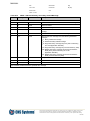
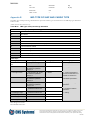
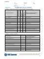
Table 2-1
Approved GPS and combined VHF/GPS antennas
Description
Mechanical data
CNS Part Number
GPS Antenna
(Procom GPS 4)
Height = 23 cm
Diameter = 33 mm
Weight = approx. 150 g
CNS2500-072
GPS Antenna
(BJTEK Navigation, MA-700)
Height = 108.5 mm
Diameter = 90.5 mm
Weight = 150 g (without cable)
CNS2500-086
Combined VHF/GPS antenna including diplexer and VHF
and GPS antenna adaptor cables
(AC marine GPS/VHF-1 including diplexer)
Height = 1.1 m
Weight = 0.65 kg
CNS2500-105
Marine GPS/VHF Antenna
(BJTEK Navigation, GVA-650P)
Height = 45 mm
Diameter = 60 mm
Weight = 65 g (without cable)
CNS2500-116
The VDL 6000 transponder type approval is valid only with certain combination of transponder and
GPS antenna.
The VDL 6000 transponder must be installed according to the Installation, Maintenance and Repair
Manual [3].
This document and attachments shall remain our property. They may not without our written consent, either
in their original state or with any changes, be copied or reproduced, disclosed to or delivered to anyone
unauthorized nor used for other purposes than what has been confirmed by C.N.S. Systems AB in writing.
BL0119C
MANUAL
2.1
[1]
[2]
[3]
[4]
[5]
[6]
Date
Classification
Page
2012-12-06
Unclassified
8 (85)
Document No.
Issue
CNSS-11-1893
J
Applicable standards and regulations
Technical characteristics for a universal shipborne automatic identification system using time division multiple access
in the VHF maritime mobile band, ITU-R M.1371-4: 2010
Maritime Navigation and Radio Communication Equipment and Systems – Digital Interfaces: Part 1 – Single Talker
and Multiple Listeners, IEC 61162-1{ed4.0}: 2010
Installation, Maintenance and Repair Manual, CNSS-11-1601
IALA Recommendation A-124 Annex 17, Channel management by an AIS Service
CCNR Vessel Tracking and Tracing Standard for Inland Navigation edition 1.01 (2007)
CCNR Vessel Inland AIS Ship borne Equipment - According to the Vessel Tracking and Tracing Standard Operational and Performance Requirements, Methods of Test and Required Test Results (Test Standard for Inland
AIS) edition 1.01 (2008)
This document and attachments shall remain our property. They may not without our written consent, either
in their original state or with any changes, be copied or reproduced, disclosed to or delivered to anyone
unauthorized nor used for other purposes than what has been confirmed by C.N.S. Systems AB in writing.
BL0119C
MANUAL
Date
Classification
Page
2012-12-06
Unclassified
9 (85)
Document No.
Issue
CNSS-11-1893
J
3
HOW TO USE THIS MANUAL
3.1
Manual Overview
This User’s Manual provides information required to operate the VDL 6000 transponder and fully take advantage of the
many features. Where there are parts of the content that are specific for only Class A or Inland, that part has a text: Class A
only or Inland only.
This manual is divided into the following sections:
Section 3
How to use this manual
Section 4
About AIS
Section 5
Installation overview
Section 6
Initial configuration
Section 7
Using the transponder
Section 8
NMEA Reference manual
Appendix A
MKD Key Layout
Appendix B
IMO Type of ship and cargo type
Appendix C
ERI ship types (Inland only)
Appendix D
Alarms and status changes
This manual is intended to be used together with the Installation, Maintenance and Repair manual [3].
3.2
Icons
Throughout this manual, the following icons are used to highlight areas of special interest and importance.
Note
Caution
This document and attachments shall remain our property. They may not without our written consent, either
in their original state or with any changes, be copied or reproduced, disclosed to or delivered to anyone
unauthorized nor used for other purposes than what has been confirmed by C.N.S. Systems AB in writing.
BL0119C
MANUAL
Date
Classification
Page
2012-12-06
Unclassified
10 (85)
Document No.
Issue
CNSS-11-1893
J
4
ABOUT AIS
4.1
Basics
The AIS concept is based on automatic data exchange between ships and between ships and shore stations. Information is
sent over an advanced digital VHF data link, where each AIS station gets its own time slot(s) for transmission of data. This
means that each one of the stations can receive information transmitted from the others without any transmission conflicts.
The capacity of the data link can theoretically handle several thousands of AIS stations within VHF radio range from each
other at the same time without overload.
The successful establishment of the network requires that all stations are synchronized, and each AIS station is therefore
equipped with an embedded GNSS receiver providing a common and accurate time reference.
In terms of ship borne equipment this description mainly refers to AIS Class A, which will be required by all ships covered
by the SOLAS convention and the IMO AIS carriage requirement. The standard for AIS Class B is intended for nonSOLAS vessels such as vessels for domestic traffic, smaller ships, fishing boats and pleasure craft.
The core unit for ship borne AIS operation, which is defined by international standards, is the VDL 6000 transponder. The
VDL 6000 transponder consists of the following main parts:
A VHF transceiver, for the radio communication
An embedded computer, handling the information exchange
A GNSS receiver, for time synchronization
An AIS Class A/Inland system also requires a Minimum Keyboard and Display (MKD) unit, providing basic control and
display functions.
4.2
Information Exchange
The information distributed in the AIS network is to a large extent standardised, but AIS also offers the possibility to
exchange free text messages or virtually any information that can be digitalized, provided that the corresponding
functionality is available on board or at a shore station.
The information distributed between ships gives significantly improved situation awareness when the AIS information is
correlated with information provided by e.g. the radar, and integrated into the ships Electronic Chart Display System.
The communication between ships and shore stations not only give a shore authority, a VTS or other ground-based parties
a real-time awareness of the ship movements, but also offers services to the ships. This could e.g. include distribution of
ARPA targets, weather information and aids-to-navigation data.
The remotely located shore stations can also be connected to a network of regionally and centrally placed operations or
management centres, offering a great flexibility and redundancy. Dependent on the required functionality, customer specific
application software can be developed.
The information distributed between the AIS stations is currently based upon a set of 26 different message types defined in
the standard. The definition of message types is an on-going process, and it can be assumed that new types will be added in
the future.
The overall AIS operation is divided into the following operational modes:
Autonomous and continuous mode – automatic broadcast transmissions without any external control (although
the mode as such may be set from a so called competent authority)
Assigned mode – transmission intervals and/or allocation of time slots are controlled by a competent authority
Polled or interrogated mode – transmission occurs in response to an interrogation from a ship or competent
authority
Each message type is associated with one or more operational modes, where the message may be used.
This document and attachments shall remain our property. They may not without our written consent, either
in their original state or with any changes, be copied or reproduced, disclosed to or delivered to anyone
unauthorized nor used for other purposes than what has been confirmed by C.N.S. Systems AB in writing.
BL0119C
MANUAL
4.3
Date
Classification
Page
2012-12-06
Unclassified
11 (85)
Document No.
Issue
CNSS-11-1893
J
Ship Information
The information autonomously sent from a ship can be divided into three groups:
Static information
Static Information is broadcast every 6 minutes, when data is amended or on request by a competent authority.
Dynamic information
This information is broadcasted with an update rate depending on the current speed and course alteration, from 2
seconds to 3 minutes. Normally the update rate is 10 seconds.
Voyage related information
This information is broadcasted every 6 minutes, when data is amended or on request by a competent authority.
4.3.1
Static Information
Static information is entered into the VDL 6000 transponder at the installation of the unit and should normally not be
changed, unless the ship for example changes name.
The following information is entered, see section 6.
Initial configuration:
MMSI
Name
Call sign (ATIS Callsign for AIS Inland vessels)
IMO Number
Dimensions of ship and location of position fixing antenna
Blue Sign, connected or not connected (Inland only)
Length and beam (Inland only)
Unique European Vessel Identification Number (ENI) (Inland only)
ERI vessel type, see Appendix C (Inland only)
Quality of speed, course and heading information (Inland only)
4.3.2
Dynamic Information
Dynamic information is automatically updated from the ship sensors connected to the VDL 6000 transponder.
The following information is provided:
Ship position with accuracy indication and integrity status
Position Time stamp in UTC
Course over ground (COG)
Speed over ground (SOG)
Rate of turn (ROT)
Heading
Navigational status
Engaged in special manoeuvre, Blue sign set / not set (Inland only)
This document and attachments shall remain our property. They may not without our written consent, either
in their original state or with any changes, be copied or reproduced, disclosed to or delivered to anyone
unauthorized nor used for other purposes than what has been confirmed by C.N.S. Systems AB in writing.
BL0119C
MANUAL
4.3.3
Date
Classification
Page
2012-12-06
Unclassified
12 (85)
Document No.
Issue
CNSS-11-1893
J
Voyage Related Information
Voyage related information is manually entered and updated during the voyage.
The following information is provided:
Ship draught
Type of ship and cargo type (Hazardous cargo)
Destination and ETA
Number of passengers, crew and ship board personnel on board
Number of assisting tugs (Inland only)
Load status, loaded/unloaded (Inland only)
Air draught (Inland only)
Throughout this manual both the expressions GNSS and GPS are used. These should in this manual
be considered the same.
This document and attachments shall remain our property. They may not without our written consent, either
in their original state or with any changes, be copied or reproduced, disclosed to or delivered to anyone
unauthorized nor used for other purposes than what has been confirmed by C.N.S. Systems AB in writing.
BL0119C
MANUAL
5
Date
Classification
Page
2012-12-06
Unclassified
13 (85)
Document No.
Issue
CNSS-11-1893
J
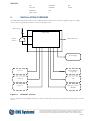
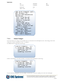
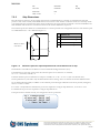
INSTALLATION OVERVIEW
The VDL 6000 transponder includes a built-in MKD and physical interfaces for external equipment and power supply.
An overview of a typical AIS installation is shown in the figure below.
VHF antenna
Transponder
GNSS
antenna
Maintenance Port
Power Supply
Sensor 1
External Display /
Long range
Sensor 2
Pilot
Sensor 3
Blue sign / alarm /
DGNSS
Figure 5-1
Installation overview
The two interfaces External Display and Pilot provide the functionality required by the Presentation Interface (PI) of an AIS
system.
This document and attachments shall remain our property. They may not without our written consent, either
in their original state or with any changes, be copied or reproduced, disclosed to or delivered to anyone
unauthorized nor used for other purposes than what has been confirmed by C.N.S. Systems AB in writing.
BL0119C
MANUAL
Date
Classification
Page
2012-12-06
Unclassified
14 (85)
Document No.
Issue
CNSS-11-1893
J
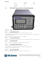
5.1
VDL 6000 Transponder Front Panel Description
Figure 5-1
Front panel
5.1.1
Power Indicator LED
The power indication (POW) is lit GREEN, when the VDL 6000 transponder is powered up.
A flashing LED indicates that the software boot sequence is executed or that proper power is not available and the shut
down sequence has been initiated.
LED off indicates that the VDL 6000 transponder is not power supplied.
5.1.2
Blue sign (Inland only)
The Blue sign indicator (BLUE) is primarily used for Inland units and is lit BLUE when the Blue sign digital input is active.
5.1.3
Tx Indicator LED
The Tx (TX) indicator flashes YELLOW when the VDL 6000 transponder transmits.
5.1.4
Rx and DSC Indicator LED’s
The Rx indicator flashes YELLOW when the VDL 6000 transponder receives.
RXA (AIS Channel A) and RXB (AIS Channel B) indicate reception of AIS TDMA messages.
DSC indicates reception of DSC telecommands.
5.1.5
Alarm Indicator LED
The alarm indication (ALR) is lit RED when the built-in test has generated an alarm.
This document and attachments shall remain our property. They may not without our written consent, either
in their original state or with any changes, be copied or reproduced, disclosed to or delivered to anyone
unauthorized nor used for other purposes than what has been confirmed by C.N.S. Systems AB in writing.
BL0119C
MANUAL
6
Date
Classification
Page
2012-12-06
Unclassified
15 (85)
Document No.
Issue
CNSS-11-1893
J
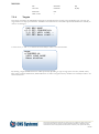
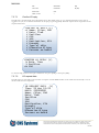
INITIAL CONFIGURATION
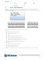
The MKD in the front of the VDL 6000 transponder is equipped with a text display containing eight lines with 21
characters each and a 16-button keyboard. When the VDL 6000 transponder is powered up for the first time the view below
will be displayed on the MKD.
VDL 6000 AIS
No valid time
MMSI: 000000000
Callsign: -
1
Space
6
MNO
2
ABC
←7
PQRS
↑3
DEF
↓8
TUV
4
5
GHI
JKL
→9
0
WXYZ
CLR/
ALAR
M
ESC
SYM
MENU
ALT
ENT
Data that should be configured when starting a transponder for the first time are:
Static data:
MMSI (Maritime Mobile Service Identity)
IMO number (where available),
Name
Call sign (ATIS Callsign for AIS Inland vessels)
Blue Sign, connected or not connected (Inland only)
Unique European Vessel Identification Number (ENI) (Inland only)
ERI vessel type, see Appendix C (Inland only)
Quality of speed, course and heading sensors (Inland only)
Ship Dimensions:
Dimension (length and beam) (Inland only)
Location of internal position source
Location of external position source
See section 7.2.1 and Figure 7-1 on how to access these menu entries. Refer to section 7.5 on how to configure data.
This document and attachments shall remain our property. They may not without our written consent, either
in their original state or with any changes, be copied or reproduced, disclosed to or delivered to anyone
unauthorized nor used for other purposes than what has been confirmed by C.N.S. Systems AB in writing.
BL0119C
MANUAL
7
Date
Classification
Page
2012-12-06
Unclassified
16 (85)
Document No.
Issue
CNSS-11-1893
J
USING THE VDL 6000 TRANSPONDER
The MKD is the user interface of the VDL 6000 transponder, where configuration and control is performed. The
functionality provided by the MKD can to a large extent also be handled by external equipment through the Presentation
Interface.
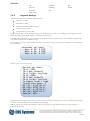
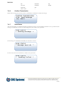
7.1
Start the VDL 6000 transponder
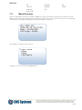
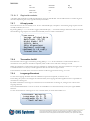
When the transponder is powered up and has been configured according to section 6 the MKD display shows a text similar
to this.
VDL 6000 AIS
No valid time
MMSI: 012345678
Callsign: CNSS1
1
Space
6
MNO
2
ABC
←7
PQRS
↑3
DEF
↓8
TUV
4
5
GHI
JKL
→9
0
WXYZ
CLR/
ALAR
M
ESC
SYM
MENU
ALT
ENT
When the VDL 6000 transponder correctly receives UTC time, current date and time is displayed. With a correct GPS
installation this should occur within 2 minutes. If no time has been received after 15 minutes, refer to [3] for GPS
installation issues.
VDL 6000 AIS
2010-03-22 10:53:09
MMSI: 012345678
Callsign: CNSS1
This document and attachments shall remain our property. They may not without our written consent, either
in their original state or with any changes, be copied or reproduced, disclosed to or delivered to anyone
unauthorized nor used for other purposes than what has been confirmed by C.N.S. Systems AB in writing.
BL0119C
MANUAL
7.2
Date
Classification
Page
2012-12-06
Unclassified
17 (85)
Document No.
Issue
CNSS-11-1893
J
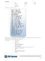
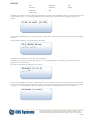
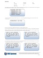
Menu Overview
When the VDL 6000 transponder is started the MKD always displays the default view presenting the current UTC time,
MMSI number and Callsign (ATIS Callsign for AIS Inland vessels) for the own ship. To return to this view after operating
the menu press [ALT] followed by [ESC], alternatively press [ESC] several times.
VDL 6000 AIS
2010-03-22 10:53:09
MMSI: 012345678
Callsign: CNSS1
Press [MENU] in order to enable the menu.
START VIEW
>Show
Send
Configure
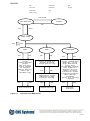
See Figure 7-1 for an overview of the MKD menus.
This document and attachments shall remain our property. They may not without our written consent, either
in their original state or with any changes, be copied or reproduced, disclosed to or delivered to anyone
unauthorized nor used for other purposes than what has been confirmed by C.N.S. Systems AB in writing.
BL0119C
MANUAL
Date
Classification
Page
2012-12-06
Unclassified
18 (85)
Document No.
Issue
CNSS-11-1893
J
CLR/ALARM
ALARMS
VDL 6000 AIS
ESC
ESC
MENU
START VIEW
ENT
ESC
SHOW
ESC
SEND
ENT
Alarms
Safety messages
Targets
Own ship data
Status changes
LR requests
Region settings
About AIS
Shutdown logs
ESC
CONFIGURE
ENT
Safety Related Text
Persons On Board
Inland Specific Msg
ESC
ENT
Addressed to target
Addressed to MMSI
Broadcast message
ESC
ENT
Show selection
Figure 7-1
ESC
ENT
Compose message
ESC
ENT
Voyage related data
Backlight (15/15)
Night mode On/Off
Static data
Inland Mode (Inland)
Ship dimensions
Regional settings
Manual LR reply
Transmitter On/Off
Longrange broadcast
GNSS settings
Passwords
Serial Port setting
Language
ESC
ENT
Configure
selection
Overview of the MKD menus
This document and attachments shall remain our property. They may not without our written consent, either
in their original state or with any changes, be copied or reproduced, disclosed to or delivered to anyone
unauthorized nor used for other purposes than what has been confirmed by C.N.S. Systems AB in writing.
BL0119C
MANUAL
7.2.1
Date
Classification
Page
2012-12-06
Unclassified
19 (85)
Document No.
Issue
CNSS-11-1893
J
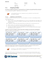
Navigating the Menu
The display on the MKD contains one title row and seven menu rows. The menu rows are scrolled vertically by pressing the
arrows ↑ and ↓, and by pressing [ENT] the currently marked () data or submenu is selected. In order to leave an entry or
to abort press [ESC]. See Appendix A - MKD Key Layout for more details.
Use the [ALT] button prior to the vertical arrows ↑ & ↓ to go directly to top or bottom of the
current menu or submenu.
7.2.1.1
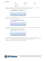
Indications on the Title Row
In addition to the name of the current menu there are up to four indications on the title row surrounded by parenthesis.
The possible indications are:
A
There is (at least) one active unacknowledged alarm (see 7.3.1 for how to acknowledge alarms). This indication will
be flashing to draw the attention of the indication. This indication follows the behaviour of the Alarm LED on the
front panel, see 5.1.2.
M An addressed or broadcast safety related message has been received but has not yet been viewed, see 7.3.2.
S
There is (at least) one not viewed status change for the VDL 6000 transponder, see 7.3.6.
L
At least one long range request has been received during manual LR reply mode, see 7.3.7.
I
This indication is available for Inland AIS transponders only. At least one inland specific functional message has
been received and not yet viewed, see 7.3.3.
To indicate to the user that the MKD is working correctly and that the display has not frozen there is a blinking dot in
addition to the indications above. However when an alarm is active the flashing alarm indication makes the additional
blinking dot unnecessary. See examples below.
VDL 6000 AIS
(AMSL)
2010-03-22 10:53:10
MMSI: 012345678
Callsign: CNSS1
VDL 6000 AIS
( MSL)
2010-03-22 10:53:11
MMSI: 012345678
Callsign: CNSS1
VDL 6000 AIS
(AMSL)
2010-03-22 10:53:12
MMSI: 012345678
Callsign: CNSS1
VDL 6000 AIS
.(MS)
2010-03-22 10:53:25
MMSI: 012345678
Callsign: CNSS1
VDL 6000 AIS
(MS)
2010-03-22 10:53:26
MMSI: 012345678
Callsign: CNSS1
VDL 6000 AIS
.(ML)
2010-03-22 10:53:27
MMSI: 012345678
Callsign: CNSS1
These indications are always shown except in some data input modes that are considered to be temporary. If the indications
together with the name of the current menu does not fit entirely in the title row, (exceeds the maximum number of
characters for the MKD display) two dots (..) are added before the indication parenthesis.
For the ‘M’, ‘S’, ‘L’ and ‘I’ indication it is important that they are cleared as they appear, in order to
see new indications (see 7.3.2, 7.3.6, 7.3.7 and 7.3.3).
Alarms are presented as ‘popup’ views when they occur (see 7.2.5) so they do not need to be cleared in order to get an
indication for a new alarm. If the source of an alarm returns to a normal state the indication is removed, even though the
alarm may have not been acknowledged.
This document and attachments shall remain our property. They may not without our written consent, either
in their original state or with any changes, be copied or reproduced, disclosed to or delivered to anyone
unauthorized nor used for other purposes than what has been confirmed by C.N.S. Systems AB in writing.
BL0119C
MANUAL
7.2.2
Date
Classification
Page
2012-12-06
Unclassified
20 (85)
Document No.
Issue
CNSS-11-1893
J
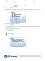
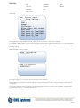
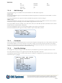
SHOW Menu
The SHOW menu consists of nine submenus showing alarms, incoming and outgoing safety related messages, received
targets, own ship data, status changes, long range requests, region settings, AIS versions and the event log.
SHOW
>Alarms
Safety messages
Targets
Own ship data
Status changes
LR requests
Region settings
About AIS
Event log
The details of each sub menu are described in 7.3.
7.2.3
SEND Menu
In this menu the transmission of some types of messages can be initiated. Each menu item leads to a submenu for the
corresponding message type.
For a Class A transponder the available selections are:
Safety Related Text
Persons On Board
For an Inland AIS transponder the available selections are:
Safety Related Text
Persons On Board
Inland Specific Msg
SEND
>Safety Related Text
Persons On Board
Inland specific Msg
The details of each sub menu are described in 7.4.
This document and attachments shall remain our property. They may not without our written consent, either
in their original state or with any changes, be copied or reproduced, disclosed to or delivered to anyone
unauthorized nor used for other purposes than what has been confirmed by C.N.S. Systems AB in writing.
BL0119C
MANUAL
7.2.4
Date
Classification
Page
2012-12-06
Unclassified
21 (85)
Document No.
Issue
CNSS-11-1893
J
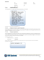
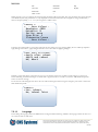
CONFIGURE Menu
All configurable data is available under this menu and consists of ten submenus.
CONFIGURE
>Voyage related data
Backlight (15/15)
Night mode: Off
Static data
Ship dimensions
Regional settings
Manual LR reply
Transmitter On
Longrange broadcast
GNSS settings
Passwords
Serial Port setting
Language
The details of each sub menu are described in 7.5.
7.2.4.1
Keyboard access to special symbols
Some configuration entries in the menu will allow you to enter both alphanumeric text and special symbols using the front
panel keyboard. Enable the symbol input menu by pressing [ALT] prior to [SYM] when entering alphanumerical input. See
Appendix A - MKD Key Layout for more details.
7.2.4.2
Password protection
Some configuration is password protected. There are two password levels: administrator and user, also identified as level 1
and 2. The administrator password gives access to all protected areas and the user level gives access to some protected areas.
Letters, numbers and symbols can be used in a password but when a password is entered in the MKD it is case insensitive
since it is only possible to enter upper case letters in the MKD.
The default passwords are:
Administrator level (1):
password
User level (2):
password
When entering a password protected area the user will be asked to enter a password with the lowest level needed in
parenthesis. For example:
ENTER PASSWORD (2)
_
This document and attachments shall remain our property. They may not without our written consent, either
in their original state or with any changes, be copied or reproduced, disclosed to or delivered to anyone
unauthorized nor used for other purposes than what has been confirmed by C.N.S. Systems AB in writing.
BL0119C
MANUAL
Date
Classification
Page
2012-12-06
Unclassified
22 (85)
Document No.
Issue
CNSS-11-1893
J
In this case both the administrator and the user password is valid to enter the protected area.
The areas protected with an administrator password are:
Serial Port settings
Static Data configuration
Transmitter On/Off
Longrange broadcast
Ship dimensions (Class A transponder only)
The areas protected with a user password are:
Long Range reply mode
To change the passwords see section 7.5.11.
7.2.5
Alarm Popup
When an alarm is generated the user’s attention is attracted by a popup view. The MKD display is lit up to maximum and
presents the alarm with the word “ALARM” flashing in the title. The alarm popup overrides all other views.
NEW ALARM [ESC/CLR]
Time: 18 Jan 11:46
Text: AIS: Heading l
ost/invalid
The user can choose to either acknowledge the alarm by pressing [CLR] or to abort by pressing [ESC]. When choosing to
abort it is possible to acknowledge the alarm in the alarm menu later on, see 7.3.1. When the alarm is acknowledged or the
view is aborted the MKD display returns to configured backlight level, see 7.5.2, and the former view returns.
7.3
SHOW
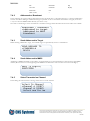
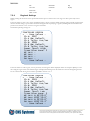
7.3.1
Alarms
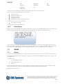
All active and unacknowledged alarms are displayed in this menu and at the bottom there is a sub menu for alarm history.
The alarms in this menu and in the alarm history sub menu are presented with and indicator and the first 17 letters of the
alarm description.
The indicators are:
*
Unacknowledged and active
A
Acknowledged and active
I
Inactive
The maximum combined number of alarms displayed in the alarms and alarm history menus is 20. After that the oldest
alarm in the alarm history is removed if a new alarm occurs. See Table D-52 for supported alarms.
Example of the Alarms menu:
This document and attachments shall remain our property. They may not without our written consent, either
in their original state or with any changes, be copied or reproduced, disclosed to or delivered to anyone
unauthorized nor used for other purposes than what has been confirmed by C.N.S. Systems AB in writing.
BL0119C
MANUAL
Date
Classification
Page
2012-12-06
Unclassified
23 (85)
Document No.
Issue
CNSS-11-1893
J
ALARMS
(A)
>* No valid ROT info
* Tx malfunction
* Heading lost/inva
* External EPFS los
Alarm history
Select an alarm to acknowledge and/or to view alarm data. The alarm is presented with date and time of occurrence and a
short description.
ALARM DATA
( )
Time: 23 Mar 15:37
Text: AIS: No valid
ROT information
To leave the alarm data view use [CLR] to acknowledge the alarm or [ESC] to leave the state unchanged.
When there is at least one active and unacknowledged alarm it is indicated by a flashing ‘A’ on the title row (se 7.2.1.1).
7.3.1.1
Alarm History
The Alarm history menu contains alarms that are active but has been acknowledged and alarms that are no longer active.
Note that alarms of the same character can exist more than once if the alarm occurs at different times.
ALARM HISTORY
( )
A No valid ROT info
>I No valid COG info
I No valid SOG info
I Heading lost/inva
I External EPFS los
This document and attachments shall remain our property. They may not without our written consent, either
in their original state or with any changes, be copied or reproduced, disclosed to or delivered to anyone
unauthorized nor used for other purposes than what has been confirmed by C.N.S. Systems AB in writing.
BL0119C
MANUAL
Date
Classification
Page
2012-12-06
Unclassified
24 (85)
Document No.
Issue
CNSS-11-1893
J
Select an alarm to view the alarm date and time of occurrence and a short description.
ALARM DATA
(A)
Time: 23 Mar 13:04
Text: AIS: No valid
COG information
7.3.1.2
Rx malfunction
When the transponder detects Rx malfunction an ALR sentence is sent:
ID003 (RX1)
ID004 (RX2)
ID005 (DSC)
See Appendix D.
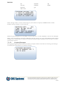
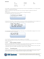
7.3.2
Safety Messages
Incoming and outgoing safety messages are stored and are available for viewing. Maximum number of stored messages is 20
for outgoing and 20 for incoming. When the number of incoming messages exceeds 20, the oldest message that has been
“viewed” (see 7.3.2.1) is removed. When the number of outgoing messages exceeds 20 the oldest transmission (or attempted
transmission) is removed. In the parenthesis for each type the number of messages saved is shown.
To send messages see 7.4.
SAFETY MESSAGES
>Incoming (3)
Outgoing (2)
7.3.2.1
(M)
Incoming Messages
The incoming messages are presented with an indicator ‘*’, ‘A’ or ‘B’ to the left of the message indicating the state of the
message:
*
Not viewed
A
Viewed addressed message
B
Viewed broadcast message
The messages are sorted by view state first and time of reception second, thus the most recently received and not viewed
message is presented first.
This document and attachments shall remain our property. They may not without our written consent, either
in their original state or with any changes, be copied or reproduced, disclosed to or delivered to anyone
unauthorized nor used for other purposes than what has been confirmed by C.N.S. Systems AB in writing.
BL0119C
MANUAL
Date
Classification
Page
2012-12-06
Unclassified
25 (85)
Document No.
Issue
CNSS-11-1893
J
INCOMING MESSAG..(M)
>* TEXT IN ADDRESSED
A OTHER ADDRESSED M
B TEXT IN SAFETY BR
Select a message in order to view the whole message text, date and time of reception, and MMSI number of sender.
Scroll the message vertically to view the whole text.
MESSAGE DATA
(M)
Time: 23 Mar 15:06
MMSI: 75940
Text: TEXT IN ADDRES
SED SAFETY MESSAGE
When leaving the message data view use [CLR] to set the message state to “viewed” and [ESC] to leave the state unchanged.
When a safety related message is received it is indicated by ‘M’ on the title row (see 7.2.1.1). This indication remains until the
message is set to “viewed” hence it is important to keep the incoming message list updated in order to be able to see when a
new message is received.
7.3.2.2
Outgoing Messages
The outgoing messages are presented with time (hh:mm) of reception and the 13 first letters of the message. The messages
are listed by time of transmission (or transmission attempt).
OUTGOING MESSAGES
>12:52 ANYBODY OUT T
12:51 HELP
This document and attachments shall remain our property. They may not without our written consent, either
in their original state or with any changes, be copied or reproduced, disclosed to or delivered to anyone
unauthorized nor used for other purposes than what has been confirmed by C.N.S. Systems AB in writing.
BL0119C
MANUAL
Date
Classification
Page
2012-12-06
Unclassified
26 (85)
Document No.
Issue
CNSS-11-1893
J
Select a message in order to view time and date of transmission, address (MMSI number), transmission status (Ok, Failure
or Processing) and the message text. The view needs to be scrolled vertically in order to see all the data.
MESSAGE DATA
Time: 23 Mar 12:52
Address: Broadcast
Sent: Ok
Text: ANYBODY OUT TH
ERE?
If the message was addressed it is presented whether the message has been acknowledged by the receiver (Yes or No).
7.3.3
Inland Messages (Inland only)
The latest 20 received inland specific functional messages are stored and are available for viewing in this submenu. Messages
that has not yet been viewed are presented with a ‘*’ as an indicator. The list of messages is sorted with unviewed messages
on top. Select a message and press [ENT] to view the details of a message.
INLAND MESSAGES..(M)
>*EMMA Warning
*Water Levels
Signal Status
EMMA Warning
This document and attachments shall remain our property. They may not without our written consent, either
in their original state or with any changes, be copied or reproduced, disclosed to or delivered to anyone
unauthorized nor used for other purposes than what has been confirmed by C.N.S. Systems AB in writing.
BL0119C
MANUAL
7.3.4
Date
Classification
Page
2012-12-06
Unclassified
27 (85)
Document No.
Issue
CNSS-11-1893
J
Targets
The targets received by the VDL 6000 transponder are presented in a list showing range and bearing from own ship, the
target nearest own ship is presented first. In addition the 12 first letters of the name is presented. Scroll the list vertically in
order to see all targets.
RNG
>2.0
5.6
120
BRG
095
125
085
NAME
CINDERELLA
VERY LONG ..
Base stati..
Use the arrows, ← and →, to scroll the list horizontally in order to view the full name.
NAME
>CINDERELLA
VERY LONG NAME
Base station
By selecting a target detailed information will be presented, depending on type of target (Class A station, Class B station,
Base station, Airborne SAR station, Inland AIS station or Aids to navigation station). Scroll the list vertically in order to see
all the information.
This document and attachments shall remain our property. They may not without our written consent, either
in their original state or with any changes, be copied or reproduced, disclosed to or delivered to anyone
unauthorized nor used for other purposes than what has been confirmed by C.N.S. Systems AB in writing.
BL0119C
MANUAL
Date
Classification
Page
2012-12-06
Unclassified
28 (85)
Document No.
Issue
CNSS-11-1893
J
Example of a received Class A station:
VERY LONG NAME
Type: Class A
MMSI: 000123456
Callsign: CNSS2
Destination:
GOTHENBURG
ETA: 27 Apr 14:47
IMO: 100037654
Lat: N 57°46.76’
Lon: E019°29.37’
PA: Low >10 m
COG: 77.6 deg
SOG: 12.1 knots
HDG: 077.8 deg
ROT: 003.2 deg/min
NAV Status: 00
Under way using engi
Type if ship: 58
Length: 32 m
Beam: 7 m
Dimension A: 21 m
Dimension B: 11 m
Dimension C: 4 m
Dimension D: 3 m
DTE: Available
Draught: 2.3 m
For all targets the Name is presented on the title row and in addition to that MMSI, position (latitude and longitude) and
position accuracy (PA) are presented on the scrollable menu rows.
Depending of type of target additional details is presented;
Class A station
Radio callsign
Destination
ETA,
IMO number
Course over ground (COG)
Speed over ground (SOG)
True heading (HDG)
Rate of turn (ROT)
Navigational status by number and by description (see table 7-1)
Type of ship (see Appendix B)
Length
Beam
Dimensions A, B, C, D (see 7.5.5)
Data terminal equipment (DTE)
Draught
This document and attachments shall remain our property. They may not without our written consent, either
in their original state or with any changes, be copied or reproduced, disclosed to or delivered to anyone
unauthorized nor used for other purposes than what has been confirmed by C.N.S. Systems AB in writing.
BL0119C
MANUAL
Date
Classification
Page
2012-12-06
Unclassified
29 (85)
Document No.
Issue
CNSS-11-1893
J
Class B station
Radio callsign
Course over ground (COG)
Speed over ground (SOG)
True heading (HDG)
Type of ship (see Appendix B)
Beam
Dimensions A, B, C, D (see 7.5.5)
Data terminal equipment (DTE)
Base station
Radio callsign.
SAR Aircraft
Radio callsign
Altitude
Course over ground (COG)
Speed over ground (SOG)
Data terminal equipment (DTE)
Inland station
An Inland station shows all the Class A information as well as:
Blue sign status
Hazardous cargo (Blue Cones)
ENI number
ERI ship type
Number of passengers
Number of crew members
Number of ship board personnel
Load status
Sensor qualities
Aids to navigation station
AID1 type (aids to navigation type)
Virtual flag
Dimensions A, B, C, D (see 7.5.5)
Off position indicator
SART station
In accordance with [1] an AIS Search and Rescue Transmitter transmits message 1 with
user ID 970xxyyyy and Nav. Status 14. So any station with these characteristics will be
presented as “Active SART” in the title row.
No additional information to a Class A station is displayed.
1
0 = not available = default, 01-15 = fixed aid-to-navigation, 16-31= floating aid-to-navigation.
This document and attachments shall remain our property. They may not without our written consent, either
in their original state or with any changes, be copied or reproduced, disclosed to or delivered to anyone
unauthorized nor used for other purposes than what has been confirmed by C.N.S. Systems AB in writing.
BL0119C
MANUAL
Date
Classification
Page
2012-12-06
Unclassified
30 (85)
Document No.
Issue
CNSS-11-1893
J
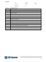
Table 7-1
Navigational status
Identifier No.
Description
00
Underway using engine
01
At anchor
02
Not under command
03
Restricted manoeuvrability
04
Constrained by her draught
05
Moored
06
Aground
07
Engaged in fishing trawling
08
Under way by sailing
09
Engaged in fishing other than trawling
10
Air cushion vessel in non displacement mode or WIG craft taking off, landing or in flight
11
Power driven vessel towing astern
12
Power driven vessel pushing ahead or towing alongside
13
In distress or requiring assistance
14
AIS SART, seeking to attract attention
15
Not defined, default
This document and attachments shall remain our property. They may not without our written consent, either
in their original state or with any changes, be copied or reproduced, disclosed to or delivered to anyone
unauthorized nor used for other purposes than what has been confirmed by C.N.S. Systems AB in writing.
BL0119C
MANUAL
7.3.5
Date
Classification
Page
2012-12-06
Unclassified
31 (85)
Document No.
Issue
CNSS-11-1893
J
OwnShip Data
The ownship data and status is displayed in the three sub-screens Static data, Voyage related data and Dynamic data.
Selecting one and pressing [ENT] will display one of the corresponding screens below.
Some views needs to be scrolled vertically in order to see all the data.
Properties with several data parameters are presented with indented lines.
OWN SHIP STATIC DATA
MMSI: 012345678
NAME:
MY NAME IS VERY LONG
Callsign: CNSS1
IMO: 987654321
Type of ship: 50
DTE: Not Available
Internal GNSS ANT:
Dimension A: 12 m
Dimension B: 109 m
Dimension C: 7 m
Dimension D: 34 m
External GNSS ANT:
Dimension A: 23 m
Dimension B: 98 m
Dimension C: 15 m
Dimension D: 26 m
OWN SHIP VOYAGE DATA
Destination:
THIS IS WHERE I GOTO
ETA: 24 Apr 13:45
Draught: 11.3 m
Persons: 34
This document and attachments shall remain our property. They may not without our written consent, either
in their original state or with any changes, be copied or reproduced, disclosed to or delivered to anyone
unauthorized nor used for other purposes than what has been confirmed by C.N.S. Systems AB in writing.
BL0119C
MANUAL
Date
Classification
Page
2012-12-06
Unclassified
32 (85)
Document No.
Issue
CNSS-11-1893
J
OWN SHIP DYNAMIC DATA
NAV Status: 03
Restricted manoeuvra
Position:
Lat: N 58°24.60’
Lon: E015°37.46’
Source: Internal
Integrity:
PA: High <10 m
RAIM: Available
DGNSS: Uncorrected
SOG: 2.3 knots
Source: Internal
COG: 138.8 deg
Source: Internal
HDG: 138.8 deg
ROT: 020.0 deg/min
7.3.6
Status Changes
The most recent status changes are presented with the 17 first letters of the description to the status change. If the status
change has not been viewed there is also a ‘*’ indicator.
See Table D-52 for supported status changes.
STATUS CHANGES
(S)
>* Internal GNSS in
* Internal SOG/COG
ROT invalid
Heading invalid
Select a status change to view date and time of occurrence and a description of the change.
STATUS CHANGES
(S)
>* Internal GNSS in
* Internal SOG/COG
ROT invalid
Heading invalid
To leave the status change data view use [CLR] to set the state to “viewed” or [ESC] to leave the state unchanged.
This document and attachments shall remain our property. They may not without our written consent, either
in their original state or with any changes, be copied or reproduced, disclosed to or delivered to anyone
unauthorized nor used for other purposes than what has been confirmed by C.N.S. Systems AB in writing.
BL0119C
MANUAL
Date
Classification
Page
2012-12-06
Unclassified
33 (85)
Document No.
Issue
CNSS-11-1893
J
When there is at least one “not viewed” status change for the VDL 6000 transponder it is indicated by ‘S’ on the title row
(see 7.2.1.1). This indication remains until the status change is set to “viewed” hence it is important to keep the status
change list updated in order to be able to se when a new status change occurs.
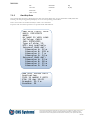
7.3.7
LR requests
The 20 most recent long range requests are presented with time (hh:mm) of reception and the MMSI of the requestor.
There is also an indicator ‘*’, ‘A’ or ‘M’ to the left of the time. The indicator depends of the setting for long range reply
mode (see 7.5.1) at the time the request was received.
‘*’ - Received in manual mode – reply needs to be confirmed
‘A’ - Received in automatic mode – needs no confirmation, has been replied
‘M’ - Received in manual mode - has been replied
Select a request to view the requested data items and/or to confirm and send a reply (if needed).
LR
>*
A
M
REQUESTS
(L)
13:31 211004000
13:38 211005000
13:30 211003000
It is indicated on the title row when there is a request that needs to be manually confirmed, see 7.3.7.1. This indication
remains until the reply has been confirmed hence it is important to keep the LR request list updated in order to be able to
see when a new LR request occurs.
This document and attachments shall remain our property. They may not without our written consent, either
in their original state or with any changes, be copied or reproduced, disclosed to or delivered to anyone
unauthorized nor used for other purposes than what has been confirmed by C.N.S. Systems AB in writing.
BL0119C
MANUAL
7.3.7.1
Date
Classification
Page
2012-12-06
Unclassified
34 (85)
Document No.
Issue
CNSS-11-1893
J
Confirm LR reply
The LR reply is presented with the requested data items. The default status ’Y’ (yes, include information in the reply) is
toggled to ‘N’ (no, do not include information in the reply) by pressing [ENT]. Scroll the request and set reply status for all
requested data items.
CONFIRM LR REPLY (L)
>Y Name, CSign, IMO
Y Data, Time
Y Position
Y COG
Y SOG
Y Destination, ETA
Y Draught
Y Type of ship
Y Dimension & type
Y Persons on board
CONFIRM LR REPLY (L)
N Date, Time
Y Position
>N COG
To send the reply and leave the reply confirmation view press [CLR], to abort press [ESC].
7.3.7.2
LR request data
The LR request is presented by time and date of reception and the MMSI number of the sender. Scroll vertically to see all
the data items that were requested.
LR REQUEST DATA (L)
Time: 23 Mar 13:31
MMSI: 211004000
Name, CSign, IMO
Data, Time
Position
COG
SOG
Destination, ETA
Draught
Type of ship
Dimension & type
Persons on board
This document and attachments shall remain our property. They may not without our written consent, either
in their original state or with any changes, be copied or reproduced, disclosed to or delivered to anyone
unauthorized nor used for other purposes than what has been confirmed by C.N.S. Systems AB in writing.
BL0119C
MANUAL
7.3.8
Date
Classification
Page
2012-12-06
Unclassified
35 (85)
Document No.
Issue
CNSS-11-1893
J
Regional Settings
AIS primarily operate with these default global settings:
Channel A no: 2087
Channel B no: 2088
Frequency bandwidth: 25kHz (A & B)
Tx power: High (12.5W)
Tx/Rx mode: Yes/Yes (A & B)
When entering a region where the default settings are not applicable (e.g. there are overriding national settings), the VDL
6000 transponder automatically switches to alternate regional settings.
The VDL 6000 transponder can store 8 regional settings defined either by ACA sentences, received DSC or AIS messages
or manually configured via the MKD, see 7.5.6.
The stored regions are presented with the north east corner position of the area. If a region is currently in use it is indicated
by a preceding ‘*’.
REGIONAL
> Reg: N
*Reg: N
Reg: N
SETTINGS
56° E 016°
59° E 016°
60° E 015°
Select a region to view all its settings.
REGION SETTINGS
Ch A: 2081
Ch A BW: Default
Ch A Tx/Rx: Yes/Yes
Ch B: 2082
Ch B BW: Default
Ch B Tx/Rx: Yes/Yes
Tx Power level: High
Transition zone: 3
NE LAT: N 60°00.0’
NE LON: E015°50.0’
SW LAT: N 59°01.0’
SW LON: E015°01.2’
Source: MKD
Beside the channel settings and the corner positions (north east latitude and longitude – south west latitude and longitude), a
transition zone surrounding the area is defined by size (1-8 NM).
When a stored region is either more than five weeks old or further away than 500 Nm from the current position it is
automatically removed.
This document and attachments shall remain our property. They may not without our written consent, either
in their original state or with any changes, be copied or reproduced, disclosed to or delivered to anyone
unauthorized nor used for other purposes than what has been confirmed by C.N.S. Systems AB in writing.
BL0119C
MANUAL
7.3.9
Date
Classification
Page
2012-12-06
Unclassified
36 (85)
Document No.
Issue
CNSS-11-1893
J
About AIS
The software and hardware versions and the unique serial number of the transponder are presented here.
TRANSPONDER VERSION
HW: VDL 6000-41-10
SW: SW-6000-12-3.X
SN: 1.44-6000-12345
This view is automatically presented when starting the VDL 6000 transponder.
7.3.10
Event Log
The transponder automatically records when the it is unable to transmit for more than 15 minutes. The reason can for
example be that the transponder is not powered or the transmitter has been set to off. The 10 most recent events are
presented with date, UTC time and reason for the log entry.
EVENT LOG
>2010-03-23 09:56:32
2010-03-21 14:32:09
2010-03-18 11:22:51
Select a log entry to view the reason for the log entry, the start time of the event and the end time.
LOG ENTRY
Reason:
Power off
Start time:
2010-03-23 09:39:32
End time:
2010-03-23 09:56:52
This document and attachments shall remain our property. They may not without our written consent, either
in their original state or with any changes, be copied or reproduced, disclosed to or delivered to anyone
unauthorized nor used for other purposes than what has been confirmed by C.N.S. Systems AB in writing.
BL0119C
MANUAL
7.4
Date
Classification
Page
2012-12-06
Unclassified
37 (85)
Document No.
Issue
CNSS-11-1893
J
SEND
In this menu the transmission of some types of messages can be initiated. Each menu item leads to a submenu for the
corresponding message type.
The submenu Inland Specific Msg is only available on Inland AIS transponders, see section 7.4.1.
Select by pressing [ENT] on any row.
SEND
>Safety Related Text
Persons On Board
Inland specific Msg
When the type of message has been selected, the operator is asked to choose if it should be sent as an addressed message or
a broadcast message, see section 7.4.2.
Next, the operator will be asked to choose the channel that the message should be transmitted on, see section 7.4.5.
Then the operator will be asked to enter the data that should be sent.
Lastly the user will be asked to confirm that the message should be transmitted, see section 7.4.6.
After the user has confirmed that a message should be sent. The send status will be presented, see section 7.4.7.
7.4.1
Inland Specific Messages (Inland only)
The following two types of Inland specific functional messages can be sent from the MKD.
ETA at lock/bridge/terminal
Number of persons on board
(RFM 21)
(RFM 55)
Select by pressing [ENT] on any row.
SEND INLAND MESSAGE
>ETA Lock/Bridge/Term
Persons On Board
This document and attachments shall remain our property. They may not without our written consent, either
in their original state or with any changes, be copied or reproduced, disclosed to or delivered to anyone
unauthorized nor used for other purposes than what has been confirmed by C.N.S. Systems AB in writing.
BL0119C
MANUAL
7.4.2
Date
Classification
Page
2012-12-06
Unclassified
38 (85)
Document No.
Issue
CNSS-11-1893
J
Addressed or Broadcast
In this submenu the operator will be asked if the message should be sent as a broadcast message or a message addressed to
another unit. When sending an addressed message it is possible to choose the address from the list of targets (see section
7.4.3) or to enter the MMSI number directly (see section 7.4.4).
Note that not all messages can be transmitted as a broadcast message and the broadcast menu choice will not be available.
Addressed / Broadcast
>Addressed to target
Addressed to MMSI
Broadcast
7.4.3
Send Addressed to Target
When selecting Addressed to target, the available targets are presented by name in a selectable list.
SEND MESSAGE TO
>CINDERELLA
DELTA
7.4.4
Send Addressed to MMSI
Addressing to MMSI will enable an input dialog for the destination. Use the numerical keys and enter the 9-digit MMSI
number (fill out with zeros in the beginning if the MMSI of the destination station consists of less than nine digits).
MMSI (9 digits)
008721598
7.4.5
Select Transmission Channel
In this dialog the channel that the message will be sent on can be selected.
Select Tx Channel
>Channel A (2087)
Channel B (2088)
Select one for me
This document and attachments shall remain our property. They may not without our written consent, either
in their original state or with any changes, be copied or reproduced, disclosed to or delivered to anyone
unauthorized nor used for other purposes than what has been confirmed by C.N.S. Systems AB in writing.
BL0119C
MANUAL
7.4.6
Date
Classification
Page
2012-12-06
Unclassified
39 (85)
Document No.
Issue
CNSS-11-1893
J
Confirm Transmission
When all the message data has been entered, a confirmation is needed to transmit the message.
CONFIRM TRANSMISSION
>Yes, send message
No, abort
7.4.7
Send Status
After the transmission is confirmed information whether the message was successfully transmitted or not is presented. If the
message was addressed, the status for acknowledgment by the receiver is also presented.
SEND STATUS
+ Sending message
+
If the message was transmitted successfully the view below is shown.
SEND STATUS
* Message sent ok
*
In case of any error in the transmission, a failure view is presented.
SEND STATUS
! Sending failed
!
This document and attachments shall remain our property. They may not without our written consent, either
in their original state or with any changes, be copied or reproduced, disclosed to or delivered to anyone
unauthorized nor used for other purposes than what has been confirmed by C.N.S. Systems AB in writing.
BL0119C
MANUAL
Date
Classification
Page
2012-12-06
Unclassified
40 (85)
Document No.
Issue
CNSS-11-1893
J
Assuming that the message was addressed and sent successfully, an acknowledgment by the addressed AIS station is
expected.
SEND STATUS
* Message sent ok *
+ Waiting for ack. +
If the acknowledgment is received the view below is shown.
SEND STATUS
* Message sent ok
* Ack. received
*
*
In case there is no acknowledgement received within 4 seconds the message is retransmitted. Retransmission in case of lack
of acknowledgement is done 3 times and if there still is no acknowledgement received a failure view is presented.
SEND STATUS
* Message sent ok *
! No ack. received !
When the final status has been presented for four seconds the status screen times out and the view returns to the send
menu.
This document and attachments shall remain our property. They may not without our written consent, either
in their original state or with any changes, be copied or reproduced, disclosed to or delivered to anyone
unauthorized nor used for other purposes than what has been confirmed by C.N.S. Systems AB in writing.
BL0119C
MANUAL
7.5
Date
Classification
Page
2012-12-06
Unclassified
41 (85)
Document No.
Issue
CNSS-11-1893
J
CONFIGURE
Static, voyage-related, and some dynamic information can be entered by means of the MKD or by means of
IEC 61162-1 [2] NMEA sentences. This section describes how to configure available data with the MKD. For an overview
of the Configure menu see section 7.2.4.
In all the configuration dialogs for specific values described in this section, use [ENT] to confirm the entered value or [ESC]
to abort to the previous menu. If the value for some reason is not accepted a message specifying why will appear.
For example:
NOT ACCEPTED
Number too big
Press [ESC] to return to the configuration dialog.
This document and attachments shall remain our property. They may not without our written consent, either
in their original state or with any changes, be copied or reproduced, disclosed to or delivered to anyone
unauthorized nor used for other purposes than what has been confirmed by C.N.S. Systems AB in writing.
BL0119C
MANUAL
7.5.1
Date
Classification
Page
2012-12-06
Unclassified
42 (85)
Document No.
Issue
CNSS-11-1893
J
Voyage Related Data
Scroll the menu vertically to see all the data.
The set of voyage related data is different in AIS Class A and AIS Inland.
AIS Class A:
SET VOYAGE DATA
> - Save Values NavStatus: 01
At anchor
Type of ship: 50
Destination: THIS..
ETA: 28 Mar 17:26
Draught: 11.3 m
Persons: 318
- Save Values AIS Inland:
SET VOYAGE DATA
> - Save Values NavStatus: 01
At anchor
ERI: Motor tanker
Type of ship: 50
Destination: THIS..
ETA: 28 Mar 17:26
Draught: 11.32 m
Passengers: 142
Crew members: 12
Ship personnel: 17
Air draught:17.87 m
No. ass. tugs: 2
Load status: Yes
Haz cargo: 1
- Save Values -
The two first rows indicate the Navigational status of the vessel. The first row is the number and the second row is the first
20 letters of the resulting status, see Table 7-1. To step between statuses, on either row use → or [ENT] to step up or ← to
step down. Both rows will change simultaneously.
Pressing [ENT] on the ERI selection will open a dialog where the ERI ship type can be entered. For more information and
valid codes see Appendix C (Inland only).
This document and attachments shall remain our property. They may not without our written consent, either
in their original state or with any changes, be copied or reproduced, disclosed to or delivered to anyone
unauthorized nor used for other purposes than what has been confirmed by C.N.S. Systems AB in writing.
BL0119C
MANUAL
Date
Classification
Page
2012-12-06
Unclassified
43 (85)
Document No.
Issue
CNSS-11-1893
J
The IMO Type of Ship and Cargo information should be in accordance with Appendix B. The type of ship can be increased
or decreased by using ← or →. Pressing [ENT] will open the dialog shown below where the appropriate value can be
entered.
TYPE OF SHIP [0-255]
_
Pressing [ENT] while Destination is selected will open a dialog where a maximum of 20 characters can be entered, including
symbols.
Pressing [ENT] while ETA is selected will open this dialog.
ETA MM/DD hh:mm
__/__ __:__
Simply enter the numbers for month, date, hour and minute.
Draught can be increased or decreased by using ← or →. Pressing [ENT] will open the dialog shown below where the
appropriate value can be entered.
Note that for AIS Inland two decimals can be entered.
DRAUGHT [0-25.5]
__._ m
Persons is only applicable to AIS Class A units and refer to the total number of persons on board the vessel. The maximum
value is 8190, the value 8191 means that there are 8191 or more persons on board. The value can be increased or decreased
by using ← or →. Pressing [ENT] will open the dialog shown below where the appropriate value can be entered.
PERSONS [0-8191]
_
This document and attachments shall remain our property. They may not without our written consent, either
in their original state or with any changes, be copied or reproduced, disclosed to or delivered to anyone
unauthorized nor used for other purposes than what has been confirmed by C.N.S. Systems AB in writing.
BL0119C
MANUAL
Date
Classification
Page
2012-12-06
Unclassified
44 (85)
Document No.
Issue
CNSS-11-1893
J
Passengers, crew members and shipboard personnel can all be increased or decreased by using ← or → (Inland only).
Pressing [ENT] will open a dialog where the appropriate value can be entered. For example:
PASSENGERS [0-8191]
_
Air draught can be increased or decreased by using ← or → (Inland only). Pressing [ENT] will open the dialog shown
below where the appropriate value can be entered.
AIR DRAUGHT[0-40.00]
__.__ m
Number of assisting tugboats can be increased or decreased by using ← or → (Inland only). Pressing [ENT] will open the
dialog shown below where the appropriate value can be entered.
ASSISTING TUGS [0-7]
_
Load status indicates if the ship is loaded. It can be toggled between Yes, No and not available by using ← or →.
Hazardous cargo should be configured to the current number of blue cones, if any. It can be can be increased or decreased
by using ← or →. Pressing [ENT] will open a dialog where the appropriate value can be entered.
Use [ESC] to apply the changes and leave the voyage related data menu.
This document and attachments shall remain our property. They may not without our written consent, either
in their original state or with any changes, be copied or reproduced, disclosed to or delivered to anyone
unauthorized nor used for other purposes than what has been confirmed by C.N.S. Systems AB in writing.
BL0119C
MANUAL
7.5.2
Date
Classification
Page
2012-12-06
Unclassified
45 (85)
Document No.
Issue
CNSS-11-1893
J
Backlight Level
The backlight level can be set from 0 – 15 where 15 is the brightest. The current value is the first value within the
parenthesis and the second value is the maximum. To increase or decrease the backlight level, use ← or →. Note that you
can quickly go from light to dark by going from 15 to 0 by pressing →.
Pressing [CLR/ALARM] will reset the backlight level to the default value of 15.
Pressing [ENT] will open the dialog shown below where the appropriate value can be entered.
BACKLIGHT(12) [0-15]
_
Pressing [ALT] + [ALT] will close down all lights to backlight level 0 (off), only alarms will be shown. Pressing any key after
that will set the light to backlight level 1.
7.5.3
Night mode
The display has a night mode that can be turned on or off. If turned on, all text will be light on a dark background instead of
the other way around. This configuration can be combined with the Backlight level to set the amount of light emitted in
night mode.
7.5.4
Static Data
To configure static data the administrator password is required, see section 7.2.4.2.
If the password was entered correctly, the configuration menu is presented.
The set of static data is different in AIS Class A and AIS Inland.
AIS Class A:
SET STATIC DATA
> - Save Values MMSI: IMO : Name: Callsign: - Save Values -
This document and attachments shall remain our property. They may not without our written consent, either
in their original state or with any changes, be copied or reproduced, disclosed to or delivered to anyone
unauthorized nor used for other purposes than what has been confirmed by C.N.S. Systems AB in writing.
BL0119C
MANUAL
Date
Classification
Page
2012-12-06
Unclassified
46 (85)
Document No.
Issue
CNSS-11-1893
J
AIS Inland:
SET STATIC DATA
> - Save Values MMSI: IMO : Name: Callsign: Blue sign: Not conne
ENI num:
SOG Sens Q: low/GNSS
COG Sens Q: low/GNSS
HDG Sens Q: low
- Save Values Pressing [ENT] on either selection will open a dialog where the respective value can be configured.
If the MMSI or IMO number consists of less than 9 digits, pad the input sequence with initial zeros to a total of nine digits.
For Name a maximum of 20 characters can be entered, including symbols, and for Callsign it’s a maximum of 7 characters
including symbols.
MMSI and IMO number example:
MMSI (9 digits)
201234567
IMO (9 digits)
000054321
The Blue sign selection refers to if an external blue sign switch has been connected or not (Inland only). The selection can
be changed, using ← or →, between “Not Connected” and “Connected”.
Pressing [ENT] on the ENI num selection will open a dialog where the ENI number, maximum 8 digits, can be entered
(Inland only).
The last three selections refer to the quality of information from the sensors for SOG, COG and HDG. Toggle between
high and low by using ←, → or [ENT] (Inland only).
This document and attachments shall remain our property. They may not without our written consent, either
in their original state or with any changes, be copied or reproduced, disclosed to or delivered to anyone
unauthorized nor used for other purposes than what has been confirmed by C.N.S. Systems AB in writing.
BL0119C
MANUAL
7.5.5
Date
Classification
Page
2012-12-06
Unclassified
47 (85)
Document No.
Issue
CNSS-11-1893
J
Ship Dimensions
Here the reference point for the reported position and the overall dimensions of the ship is configured. The reported
position is that of the currently used GNSS antenna. The location of that antenna in reference to the rest of the ship needs
to be configured. Two such reference points can be configured, one for the antenna connected to the internal GNSS in the
VDL 6000 unit and another for an antenna connected to an external GNSS unit, if present.
The reference points also define the overall dimensions of the ship and the four configurable values for each reference point
are called Dimension A – D as defined in Figure 7-2
Distance (m)
A
Reference Point
of Position
A
0-511, 511 = 511 m or greater
B
0-511, 511 = 511 m or greater
C
0-63, 63 = 63 m or greater
D
0-63, 63 = 63 m or greater
B
C
Figure 7-2
D
Reference point for reported position and overall dimensions of ship.
The dimension A should be in the direction of the transmitted heading information (bow).
If the dimensions of the ship is known but the reference point for an antenna is not available,
set A = C = 0 and B ≠ 0 and D ≠ 0.
If neither reference point nor dimensions of ship are available, set A = B = C = D = 0 (this is the default value).
The ship dimensions (A+B and C+D) should be identical when entering values for internal and external GNSS antenna.
On an Inland AIS transponder, in addition to the reference points the length and beam can be more precisely configured,
down to a tenth of a meter.
For a Class A transponder the administrator password is required to configure ship dimensions, see section 7.2.4.2.
For Inland AIS no password is required to configure ship dimensions.
If the password was entered correctly, the configuration menu is presented.
SET DIMENSIONS
>Internal GNSS ANT
External GNSS ANT
- Save Values -
This document and attachments shall remain our property. They may not without our written consent, either
in their original state or with any changes, be copied or reproduced, disclosed to or delivered to anyone
unauthorized nor used for other purposes than what has been confirmed by C.N.S. Systems AB in writing.
BL0119C
MANUAL
Date
Classification
Page
2012-12-06
Unclassified
48 (85)
Document No.
Issue
CNSS-11-1893
J
Press [ENT] on either selection to enter a sub menu where the four dimensions for the selected antenna can be configured.
The view needs to be scrolled vertically in order to see all the data.
INTERNAL GNSS ANT
>Dimension A: 0 m
Dimension B: 0 m
Dimension C: 0 m
Dimension D: 0 m
Return to menu
All values can either be step up or down using → or ← or by pressing [ENT] a dialog appears where the value can be
entered directly.
DIMENSION B [0-511]
_
Enter new setting using the alphanumerical input keys and press [ENT] to finish.
If the configured overall dimensions for internal and external GNSS antennas do not match, a warning will be presented.
Meaning, if dimension A+B for internal GNSS antenna does not match A+B for external there will be a Length warning
and if C+D for internal does not match C+D for external there will be a Beam warning.
LENGTH VALUE WARNING
The sum of the extern
al and internal posit
ion references are no
t equal.
BEAM VALUE WARNING
The sum of the extern
al and internal posit
ion references are no
t equal.
In an AIS Inland an additional check with the more precise length and beam values are made. Warnings for both external
and internal position reference can be presented. For example:
LENGTH VALUE WARNING
The sum of the extern
al position reference
values is not equal
to the Length.
BEAM VALUE WARNING
The sum of the intern
al position reference
values is not equal
to the Beam.
This document and attachments shall remain our property. They may not without our written consent, either
in their original state or with any changes, be copied or reproduced, disclosed to or delivered to anyone
unauthorized nor used for other purposes than what has been confirmed by C.N.S. Systems AB in writing.
BL0119C
MANUAL
7.5.6
Date
Classification
Page
2012-12-06
Unclassified
49 (85)
Document No.
Issue
CNSS-11-1893
J
Regional Settings
When entering this menu the user is presented with the option to either enter a new region or edit a previously stored
region.
If the user selects to enter a new region the display below is shown, with the default operating settings already entered. Note
that the channel settings or power level cannot be changed without specifying a region by defining the NE and SW corner
positions. See section 7.5.6.1 for more on region constraints.
The default operating settings are:
CONFIGURE REGION
> - Save Values Ch A: 2087
Ch A BW: Default
Ch A Tx/Rx: Yes/Yes
Ch B: 2088
Ch B BW: Default
Ch B Tx/Rx: Yes/Yes
Power level: High
Transition zone: 5
NE Lat: NE Lon: SW Lat: SW Lon: - Save Values -
If the user selects to edit a region, a list of previously stored regions will be displayed. Select one and press [ENT] to enter
the configure region screen. The selected region is displayed and changes can be made. Note that the changed region still
has to conform with the region constraints specified in section 7.5.6.1.
CONFIGURE REGION
> - Save Values Ch A: 2081
Ch A BW: Default
Ch A Tx/Rx: Yes/Yes
Ch B: 2082
Ch B BW: Default
Ch B Tx/Rx: Yes/Yes
Power level: Low
Transition zone: 3
NE Lat: N 60°00.0’
NE Lon: E015°50.0’
SW Lat: N 59°01.0’
SW Lon: E015°01.2’
- Save Values -
This document and attachments shall remain our property. They may not without our written consent, either
in their original state or with any changes, be copied or reproduced, disclosed to or delivered to anyone
unauthorized nor used for other purposes than what has been confirmed by C.N.S. Systems AB in writing.
BL0119C
MANUAL
Date
Classification
Page
2012-12-06
Unclassified
50 (85)
Document No.
Issue
CNSS-11-1893
J
The possibility to change bandwidth has been removed in newer versions of the AIS standards so it is no longer possible to
change it to something other then default.
Power level, transmit/receive mode and transition zone size settings are stepped or toggled when selected with
[ENT] ← or →.
Channel numbers (A and B) and the four corner coordinates are configured with dialogs.
For example, the latitude of the north-eastern corner.
LATITUDE NE CORNER
_ __°__._’
If changes have been made to the regional settings when leaving the menu (by pressing [ESC]), the user is prompted to save
settings and exit regional settings, abort and exit regional settings or continue editing regional settings.
SAVE SETTINGS?
>Yes, save and exit
No, abort and exit
Continue editing
If no error message is presented when attempting to save the region, it is successfully added or changed. In case of an error
a short description of the error is presented.
NOT ACCEPTED
Invalid size
To leave the error description and return to region configuration view, press [ESC].
When a stored region is either more than five weeks old or further away than 500 Nm from the current position it is
automatically removed.
7.5.6.1
Region settings constraints
There are constraints specified by the AIS standards for how regional operating areas may be defined. A few of them will be
briefly discussed in this section, for more information and details please refer to [1] and [4].
A regional operating area may be input by the following means: manual input, TDMA command from a base station, DSC
command from a base station, NMEA commands from a shipborne system (e.g. ECDIS).
7.5.6.1.1
Transmitter power
Changes to the power level should only be by assignment by the approved channel management means. This means that the
power level of the transmitter is not allowed to be changed unless inside a regional operating area entered by one of the
methods mentioned above. Hence, to change the power level a regional area must be defined.
This document and attachments shall remain our property. They may not without our written consent, either
in their original state or with any changes, be copied or reproduced, disclosed to or delivered to anyone
unauthorized nor used for other purposes than what has been confirmed by C.N.S. Systems AB in writing.
BL0119C
MANUAL
7.5.6.1.2
Date
Classification
Page
2012-12-06
Unclassified
51 (85)
Document No.
Issue
CNSS-11-1893
J
Regional boundaries
A boundary side should be no smaller than 20 Nm but no larger than 200 Nm. Care should be taken to avoid having more
than three adjacent regions at any regional boundary intersection.
7.5.7
LR reply mode
The mode shown is the one currently in use. If set to “Manual LR reply” all replies to received long range requests must be
manually confirmed, see 7.3.7.1.
By pressing [ENT], ← or → the mode is toggled, “Manual LR reply” – “Automatic LR reply”. When the mode is automatic
all received long range requests are answered automatically and in no need of confirmation.
CONFIGURE
Voyage related data
Backlight (15/15)
Night mode: Off
Static data
Ship dimensions
Regional settings
>Automatic LR reply
Transmitter On
7.5.8
Transmitter On/Off
The transmitter can be toggle on and off by pressing [ENT], ← or →. If the transmitter is turned off there will be no
transmissions of any kind, the unit will be completely silent. It will however still receive messages as usual.
When the transmitter is turned off the alarm “Tx malfunction” will become active since the transmitter is no longer in use
as intended and also to notify any external applications that the unit will no longer transmit.
If the transmitter is turned off for more than 15 minutes it will be logged in the Event log, see 7.3.10.
7.5.9
Longrange Broadcast
To enter the Longrange broadcast menu the administrator password is required, see section 7.2.4.2.
In this dialog the operator can configure the channels used by the Longrange broadcast application that is responsible for
transmission of message 27.
By default transmission of message 27 is turned off. To start transmission of message 27, configure one or both of the
longrange channels.
The recommended channels to use are 75 and 76. It is forbidden to use channels currently in use by the regular TDMA
functions.
To turn off transmission of message 27 on one or both channels, set the channel number to 0.
LONGRANGE BROADCAST
Longrange Ch 1: 75
>Longrange Ch 2: 76
- Save values -
This document and attachments shall remain our property. They may not without our written consent, either
in their original state or with any changes, be copied or reproduced, disclosed to or delivered to anyone
unauthorized nor used for other purposes than what has been confirmed by C.N.S. Systems AB in writing.
BL0119C
MANUAL
7.5.10
Date
Classification
Page
2012-12-06
Unclassified
52 (85)
Document No.
Issue
CNSS-11-1893
J
GNSS Settings
The following settings are available for the internal GNSS of the VDL 6000 transponder.
GNSS mode:
If the internal GNSS has support for GLONASS, the GNSS mode parameter commands the internal GNSS to use either
GLONASS or GPS.
If the internal GNSS only has support for GPS, the GNSS mode parameter cannot be changed.
NMEA output:
If the internal GNSS has valid data and no valid external GNSS data is received, then NMEA sentences from the internal
GNSS will be output on the display ports if the NMEA output parameter is set to ON.
The output NMEA sentences are RMC, VTG, GNS, GGA, GSA, GLL and GBS. The talker id will indicate if the internal
GNSS currently is in GLONASS or GPS mode.
If the internal GNSS has support for GLONASS the NMEA output will be ON by default.
If the internal GNSS only has support for GPS, the NMEA output will be OFF by default.
GNSS SETTINGS
GNSS mode: GPS
>NMEA output: OFF
- Save values -
7.5.11
Passwords
In this menu the passwords described in section 7.2.4.2 can be changed. To change either one of them select the Passwords
menu and then Admin or User in the sub menu. To be able to change a password the current password for the selected
level has to be entered. If the correct password is entered, enter the new password and then re-enter the new password for
verification. A password can be between 6 and 20 characters long.
7.5.12
Serial Port Settings
To configure the serial port settings for the serial interfaces, the administrator password is required, see section 7.2.4.2.
Note that parameter changes are not applied until the VDL 6000 transponder is rebooted.
Assuming that the password was correctly entered, all ports available for configuration are presented. Scroll menu vertically
and select the port to configure.
SERIAL PORT SETTINGS
> - Save Values Sensor 1
Sensor 2
Sensor 3
Long range
External display
Pilot/Auxiliary
DGNSS corrections
- Save Values -
This document and attachments shall remain our property. They may not without our written consent, either
in their original state or with any changes, be copied or reproduced, disclosed to or delivered to anyone
unauthorized nor used for other purposes than what has been confirmed by C.N.S. Systems AB in writing.
BL0119C
MANUAL
Date
Classification
Page
2012-12-06
Unclassified
53 (85)
Document No.
Issue
CNSS-11-1893
J
When choosing a port to configure the currently used parameters will be presented. The only parameter that can be changed
is the Baudrate, the other parameters are only displayed as information and cannot be changed. To change the Baudrate,
select it and press [ENT], ← or → to cycle trough the available values.
Sensor 1
> - Save Values Baudrate: 4800
Databits: 8
Parity: none
Stop bits: 1
Flowcontrol:none
- Save Values If changes have been made to port settings when leaving the settings view (by pressing [ESC]) the user will be prompted to
apply changes after reboot, apply changes and reboot or to abort without applying changes.
SAVE PORT SETTINGS?
>Apply after reboot
Apply and reboot
No, abort
Selecting “apply after reboot” will return the view to port selection, hence it is possible to make changes to other ports
before rebooting. If all desired changes are made select “apply and reboot” in order to restart the VDL 6000 transponder
and to use the new settings.
In case the user selected apply after reboot the user will be asked again when leaving the configure ports menu to reboot the
VDL 6000 transponder.
REBOOT?
>Yes, reboot
No, reboot later
7.5.13
Language
In this dialog the language used in the MKD can be configured. When selecting “Default” the language will be the same as it
was when the unit was delivered.
This document and attachments shall remain our property. They may not without our written consent, either
in their original state or with any changes, be copied or reproduced, disclosed to or delivered to anyone
unauthorized nor used for other purposes than what has been confirmed by C.N.S. Systems AB in writing.
BL0119C
MANUAL
Date
Classification
Page
2012-12-06
Unclassified
54 (85)
Document No.
Issue
CNSS-11-1893
J
This document and attachments shall remain our property. They may not without our written consent, either
in their original state or with any changes, be copied or reproduced, disclosed to or delivered to anyone
unauthorized nor used for other purposes than what has been confirmed by C.N.S. Systems AB in writing.
BL0119C
MANUAL
8
Date
Classification
Page
2012-12-06
Unclassified
55 (85)
Document No.
Issue
CNSS-11-1893
J
NMEA REFERENCE MANUAL
This section describes both standardized NMEA sentences and proprietary NMEA sentences.
All CNS Systems proprietary NMEA sentences have a name beginning with $PCNS. The fifth letter indicates the sentences
type. There are five such types:
$PCNSC
Command sentences.
$PCNSQ
Query sentences.
$PCNSR
Response to query and command sentences.
$PCNSS
Set configuration sentences.
$PCNSI
Indication sentences.
In accordance with [2] all sentences shall be transmitted with a checksum field. The checksum field is the last field in a
sentence and follows the checksum delimiter character “*”. The checksum is the eight-bit exclusive OR (no start or stop
bits) of all characters in the sentence, including “,” and “^” delimiters, between but not including the “$” or “!” and the “*”
delimiters. For more information see [2].
NMEA sentences supported on Sensor ports:
DTM, GBS, GGA, GLL, GNS, HDT, THS, HDG, OSD, RMC, ROT, VBW and VTG
NMEA sentences supported on Display ports:
ABM, BBM, ABK, VDM, VDO, ALR, TXT, ACA, ACK, AIR, SSD, VSD, AIQ, ACS, LRF, SPW, EPV and TRL
PCNSS
TXE
INL (Inland only)
PCNSR
TXE
INL (Inland only)
PCNSQ
TXE
INL (Inland only)
NMEA sentences supported only on AIS Inland on Display ports:
PIWWIVD, PIWWSSD, PIWWSPW and PIWWSPR
NMEA sentences supported on the Long Range port:
LRI, LRF, LR1, LR2 and LR3
This document and attachments shall remain our property. They may not without our written consent, either
in their original state or with any changes, be copied or reproduced, disclosed to or delivered to anyone
unauthorized nor used for other purposes than what has been confirmed by C.N.S. Systems AB in writing.
BL0119C
MANUAL
Classification
Page
2012-12-06
Unclassified
56 (85)
Document No.
Issue
CNSS-11-1893
J
DTM – Datum reference
Table 8-1
Field nr
Date
Message Field
Used / Not Used
Description
$--DTM,ccc,a,x.x,a,x.x,a,x.x,ccc*hh<CR><LF>
1
ccc
Used
Local datum code
WGS84=W84
WGS72=W72
SGS85=S85
PE90=P90
User defined=999
IHO datum code
2
a
Not used
Local datum subdivision code
3, 4
x.x,a
Not used
Latitude offset (minutes)
5, 6
x.x,a
Not used
Longitude offset (minutes)
7
x.x
Not used
Altitude offset (meters)
8
ccc
Not used
Reference datum code
WGS84=W84
WGS72=W72
SGS85=S85
PE90=P90
9
hh
Used
Checksum field
Note: Only “Local datum” supported. “Local datum” = “W84” sets the port in WGS-84 mode, other datum’s are not
supported.
GBS – Global Satellite Fault Detection
Table 8-2
Field nr
Message Field
Used / Not Used
Description
$--GBS,hhmmss.ss,x.x,x.x,x.x,xx,x.x,x.x,x.x*hh<CR><LF>
1
hhmmss.ss
Not used
UTC time of GGA or GNS fix associated with this sentence
2
x.x
Used
Expected error in Latitude
3
x.x
Used
Expected error in Longitude
4
x.x
Not used
Expected error in Altitude
5
xx
Not used
ID number of most likely failed satellite
6
x.x
Not Used
Probability of missed detection of most likely failed satellite
7
x.x
Not Used
Estimate of bias in meters of most likely failed satellite
8
x.x
Not used
Standard deviation of bias estimate
9
hh
Used
Checksum field
Note: All fields parsed. “UTC time of the GGA or GNS fix” used to indicate RAIM in use.
This document and attachments shall remain our property. They may not without our written consent, either
in their original state or with any changes, be copied or reproduced, disclosed to or delivered to anyone
unauthorized nor used for other purposes than what has been confirmed by C.N.S. Systems AB in writing.
BL0119C
MANUAL
Classification
Page
2012-12-06
Unclassified
57 (85)
Document No.
Issue
CNSS-11-1893
J
GGA – Global Positioning System Fix data
Table 8-3
Field nr
Date
Message Field
Used / Not Used
Description
$--GGA,hhmmss.ss,llll.ll,a,yyyyy.yy,a, x,xx,x.x,x.x,M,x.x,M,x.x,xxxx*hh<CR><LF>
1
hhmmss.ss
Used
UTC of position
2, 3
llll.ll,a
Used
Latitude
4, 5
yyyyy.yy,a
Used
Longitude
6
x
Used
GPS quality factor
7
xx
Not used
Number of satellites in use
8
x.x
Not used
Horizontal dilution of precision
9, 10
x.x,M
Not used
Altitude (meters)
11, 12
x.x,M
Not used
Geoidal separation (meters)
13
x.x
Not used
Age of differential GPS data
14
xxxx
Not used
Differential reference station ID
15
hh
Used
Checksum field
Note: All fields parsed, 6 first fields used for external GPS position.
GLL – Geographic Position - Latitude/Longitude
Table 8-4
Field nr
Message Field
Used / Not Used
Description
$--GLL,llll.ll,a,yyyyy.yy,a,hhmmss.ss,A,a*hh<CR><LF>
1, 2
llll.ll,a
Used
Latitude
3, 4
yyyyy.yy,a
Used
Longitude
5
hhmmss.ss
Used
UTC of position
6
A
Used
Status
7
a
Used
Mode
8
hh
Used
Checksum field
Note: All fields parsed and used for external GPS position
This document and attachments shall remain our property. They may not without our written consent, either
in their original state or with any changes, be copied or reproduced, disclosed to or delivered to anyone
unauthorized nor used for other purposes than what has been confirmed by C.N.S. Systems AB in writing.
BL0119C
MANUAL
Classification
Page
2012-12-06
Unclassified
58 (85)
Document No.
Issue
CNSS-11-1893
J
GNS – GNSS Fix Data
Table 8-5
Field nr
Date
Message Field
Used / Not Used
Description
$--GNS,hhmmss.ss,llll.ll,a,yyyyy.yy,a,c--c,xx,x.x,x.x,x.x,x.x,x.x*hh<CR><LF>
1
hhmmss.ss
Not used
UTC
2, 3
llll.ll,a
Used
Latitude
4, 5
yyyyy.yy,a
Used
Longitude
5
c--c
Used
Mode indicator
6
xx
Not used
Number of satellites in use
7
x.x
Not Used
HDOP
8
x.x
Not used
Antenna altitude (meters)
9
x.x
Not used
Geodial separation (meters)
10
x.x
Not used
Age of differential data
11
x.x
Not used
Diff reference station ID
12
hh
Used
Checksum field
Note: All fields parsed, 6 first fields used for external GPS position
HDT – Heading True
Table 8-6
Field nr
Message Field
Used / Not Used
Description
$--HDT,x.x,T*hh<CR><LF>
1, 2
x.x,T
Used
Heading, degrees true
3
hh
Used
Checksum field
Note: All fields parsed and used for external HDG
THS – True heading and status
Table 8-7
Field nr
Message Field
Used / Not Used
Description
$--THS,x.x,a*hh<CR><LF>
1
x.x
Used
Heading, degrees true
2
a
Used
Mode indicator. This field should not be null.
3
hh
Used
Checksum field
Note: All fields parsed and used for external Heading
This document and attachments shall remain our property. They may not without our written consent, either
in their original state or with any changes, be copied or reproduced, disclosed to or delivered to anyone
unauthorized nor used for other purposes than what has been confirmed by C.N.S. Systems AB in writing.
BL0119C
MANUAL
Classification
Page
2012-12-06
Unclassified
59 (85)
Document No.
Issue
CNSS-11-1893
J
HDG – Heading, deviation and variation
Table 8-8
Field nr
Date
Message Field
Used / Not Used
Description
$--HDG,x.x,x.x,a,x.x,a*hh<CR><LF>
1
x.x
Used
Magnetic sensor heading, degrees
2, 3
x.x,a
Used
Magnetic deviation, degrees E/W
4, 5
x.x,a
Used
Magnetic variation, degrees E/W
6
hh
Used
Checksum field
Note:
To obtain magnetic heading: add easterly deviation (E) to magnetic sensor reading; subtract westerly deviation
(W) from magnetic sensor reading.
To obtain true heading: add easterly variation (E) to magnetic heading; subtract westerly variation (W) from
magnetic heading.
Variation and deviation fields will be null fields if unknown.
OSD – Own Ship Data
Table 8-9
Field nr
Message Field
Used / Not Used
Description
$--OSD,x.x,A,x.x,a,x.x,a,x.x,x.x,A*hh<CR><LF>
1
x.x
Used
Heading, degrees True
2
a
Used
Heading status
3
x.x
Used
Vessel course, degrees True
4
A
Used
Course reference B/M/W/R/P
5
x.x
Used
Vessel speed
6
a
Used
Speed reference B/M/W/R/P
7
x.x
Not used
Vessel set, degrees True
8
x.x
Not used
Vessel drift (speed)
9
A
Used
Speed units, K/N/S
10
hh
Used
Checksum field
Note: All fields parsed and field 1 and 2 used for external HDG, field 3 and 4 used for external COG and field 5, 6
and 9 used for external SOG. Course and Speed references Manual and Water is not accepted
This document and attachments shall remain our property. They may not without our written consent, either
in their original state or with any changes, be copied or reproduced, disclosed to or delivered to anyone
unauthorized nor used for other purposes than what has been confirmed by C.N.S. Systems AB in writing.
BL0119C
MANUAL
Table 8-10
Field nr
Date
Classification
Page
2012-12-06
Unclassified
60 (85)
Document No.
Issue
CNSS-11-1893
J
RMC – Recommended Minimum Specific GNSS Data
Message Field
Used / Not Used
Description
$-- RMC,hhmmss.ss,A,llll.ll,a,yyyyy.yy,a,x.x,x.x, xxxxxx,x.x,a,a*hh<CR><LF>
1
hhmmss.ss
Used
UTC (used to sync 1PPS time – odd even second)
2
A
Used
Status
3, 4
llll.ll,a
Used
Latitude
5, 6
yyyyy.yy,a
Used
Longitude
7
x.x
Used
Speed Over Ground
8
x.x
Used
Course Over Ground
9
xxxxxx
Used
Date ddmmyy
10, 11
x.x,a
Not used
Magnetic variation (degrees)
12
a
Used
Mode indicator
13
hh
Used
Checksum field
Note: All fields parsed and field 1-6 and 12 used for external or manual position, field 7 used for external SOG
and field 8 used for external COG
Table 8-11
Field nr
ROT – Rate Of Turn
Message Field
Used / Not Used
Description
$--ROT,x.x,A*hh<CR><LF>
1
x.x
Used
Rate of turn
2
A
Used
Status
3
hh
Used
Checksum field
Note: All fields parsed and used for external ROT
This document and attachments shall remain our property. They may not without our written consent, either
in their original state or with any changes, be copied or reproduced, disclosed to or delivered to anyone
unauthorized nor used for other purposes than what has been confirmed by C.N.S. Systems AB in writing.
BL0119C
MANUAL
Table 8-12
Field nr
Date
Classification
Page
2012-12-06
Unclassified
61 (85)
Document No.
Issue
CNSS-11-1893
J
VBW – Dual Ground/Water Speed
Message Field
Used / Not Used
Description
$--VBW,x.x,x.x,A,x.x,x.x,A,x.x,A*hh<CR><LF>
1
x.x
Not used
Longitudinal water speed (knots)
2
x.x
Not used
Transverse water speed (knots)
3
A
Not used
Status, water speed
4
x.x
Used
Longitudinal ground speed (knots)
5
x.x
Used
Transverse ground speed (knots)
6
A
Used
Status, ground speed
7
x.x
Not used
Stern transverse water speed (knots)
8
A
Not used
Status stern water speed
9
x.x
Not used
Stern traverse ground speed (knots)
10
A
Not used
Status stern ground speed
11
hh
Used
Checksum field
Note: All fields parsed and field 4 - 6 used for external SOG
Table 8-13
Field nr
VTG – Course over Ground and Ground Speed
Message Field
Used / Not Used
Description
$--VTG,x.x,T,x.x,M,x.x;n,x.x,K,a*hh<CR><LF>
1, 2
x.x,T
Used
Course over ground, degrees True
3, 4
x.x,M
Not used
Course over ground, degrees Magnetic
5, 6
x.x,N
Used
Speed over ground (knots)
7, 8
x.x,K
Used
Speed over ground (km/h)
9
a
Used
Mode indicator
10
hh
Used
Checksum field
Note: Fields 3,4,7 and 8 are ignored, field 1 and 2 used for external COG, and field 5 and 6 used for external
SOG
This document and attachments shall remain our property. They may not without our written consent, either
in their original state or with any changes, be copied or reproduced, disclosed to or delivered to anyone
unauthorized nor used for other purposes than what has been confirmed by C.N.S. Systems AB in writing.
BL0119C
MANUAL
Table 8-14
Field nr
Date
Classification
Page
2012-12-06
Unclassified
62 (85)
Document No.
Issue
CNSS-11-1893
J
ABM – Addressed Binary and safety related Message
Message Field
Used / Not Used
Description
!--ABM,x,x,x,xxxxxxxxx,x,x.x,s—s,x*hh<CR><LF>
1
x
Used
Total number of sentences needed to transfer the message
2
x
Used
Sentence number
3
x
Used
Sequential Message identifier
4
xxxxxxxxx
Used
The MMSI of destination AIS unit for the ITU-R M.1371
message
5
x
Used
AIS channel for broadcast of the radio message
6
x.x
Used
The ITU-R M.1371 message Id for the following addressed
Messages:
6
Binary addressed message
12 Addressed safety related message
25 Single slot binary message 25 (binary data coded using
the 16-bit Application identifier)
70 Single slot binary message 25 (unstructured binary data)
26 Multiple slot binary message 26 with Communications
State (binary data coded using the 16-bit
Application identifier)
71 Multiple slot binary message 26 with Communications
State (unstructured binary data)
7
s—s
Used
Encapsulated data
8
x
Used
Number of fill-bits
9
hh
Used
Checksum field
Note: All fields parsed and used to generate VDL message
This document and attachments shall remain our property. They may not without our written consent, either
in their original state or with any changes, be copied or reproduced, disclosed to or delivered to anyone
unauthorized nor used for other purposes than what has been confirmed by C.N.S. Systems AB in writing.
BL0119C
MANUAL
Table 8-15
Field nr
Date
Classification
Page
2012-12-06
Unclassified
63 (85)
Document No.
Issue
CNSS-11-1893
J
BBM – Broadcast Binary Message
Message Field
Used / Not Used
Description
!--BBM,x,x,x,x,x.x,s—s,x*hh<CR><LF>
1
x
Used
Total number of sentences needed to transfer the message
2
x
Used
Sentence number
3
x
Used
Sequential message identifier
4
x
Used
AIS channel for broadcast of the radio message
5
x.x
Used
The ITU-R M.1371 Message ID for the following broadcast
messages:
8
Binary broadcast message
14 Safety related broadcast message
25 Single slot binary message 25 (binary data coded using
the 16-bit Application identifier),
70 Single slot binary message 25 (unstructured binary data)
26 Multiple slot binary message 26 with Communications
State (binary data coded using the 16-bit
Application identifier)
71 Multiple slot binary message 26 with Communications
State (unstructured binary data)
6
s—s
Used
Encapsulated data
7
x
Used
Number of fill-bits
8
hh
Used
Checksum field
Note: All fields parsed and used to generate VDL message
This document and attachments shall remain our property. They may not without our written consent, either
in their original state or with any changes, be copied or reproduced, disclosed to or delivered to anyone
unauthorized nor used for other purposes than what has been confirmed by C.N.S. Systems AB in writing.
BL0119C
MANUAL
Table 8-16
Field nr
Date
Classification
Page
2012-12-06
Unclassified
64 (85)
Document No.
Issue
CNSS-11-1893
J
ACA – AIS Regional Channel Assignment Message
Message Field
Used / Not Used
Description
$--ACA,x,llll.ll,a, yyyyy.yy, a,llll.ll,a,yyyyy.yy,a, x,xxxx,x,xxxx,x,x,x,a,x,hhmmss.ss*hh<CR><LF>
1
x
Used
Sequence number
2, 3
llll.ll,a
Used
Region Northeast corner latitude N/S
4, 5
yyyyy.yy,a
Used
Region Northeast corner longitude E/W
6, 7
llll.ll,a
Used
Region Southwest corner latitude N/S
8, 9
yyyyy.yy,a
Used
Region Southwest corner longitude E/W
10
x
Used
Transition Zone Size
11
xxxx
Used
Channel A
12
x
Used
Channel A bandwidth
13
xxxx
Used
Channel B
14
x
Used
Channel B bandwidth
15
x
Used
Tx/Rx mode
16
x
Used
Power lewel control
17
a
Not used
Information source
18
x
Not used
In-use Flag
19
hhmmss.ss
Not used
Time of “in-use” change
20
hh
Used
Checksum field
Note: All fields except 17,18 and 19 parsed and used to add region. For outgoing all fields are used. Field 16 only
supports the values 0, 1 and 2.
Table 8-17
Field nr
ACK – Acknowledge alarm
Message Field
Used / Not Used
Description
$--ACK,xxx*hh<CR><LF>
1
xxx
Used
Local alarm number
2
hh
Used
Checksum field
Note: All fields parsed and used to acknowledge alarms
This document and attachments shall remain our property. They may not without our written consent, either
in their original state or with any changes, be copied or reproduced, disclosed to or delivered to anyone
unauthorized nor used for other purposes than what has been confirmed by C.N.S. Systems AB in writing.
BL0119C
MANUAL
Table 8-18
Field nr
Date
Classification
Page
2012-12-06
Unclassified
65 (85)
Document No.
Issue
CNSS-11-1893
J
AIR – AIS Interrogation Request
Message Field
Used / Not Used
Description
$--AIR,xxxxxxxxx,x.x,x,x.x,x,xxxxxxxxx,x.x,x*hh<CR><LF>
1
xxxxxxxxx
Used
MMSI of interrogated station 1
2
x.x
Used
ITU-R M.1371 message requested from station 1
3
x
Not used
Message sub-section (reserved for future use)
4
x.x
Used
Number of second message from station 1
5
x
Not used
Message sub-section (reserved for future use)
6
xxxxxxxxx
Used
MMSI of interrogated station 2
7
x.x
Used
Number of message requested from station 2
8
x
Not used
Message sub-section (reserved for future use)
9
hh
Used
Checksum field
Note: All fields parsed. All fields except field 3,5 and 8 are used to generate VDL message.
Table 8-19
Field nr
SSD – Ship Static Data
Message Field
Used / Not Used
Description
$--SSD,c--c,c--c,xxx,xxx,xx,xx,c,aa*hh<CR><LF>
1
c--c
Used
Ship’s Call sign
2
c--c
Used
Ship’s name
3
xxx
Used
Pos. ref., “A” distance from bow
4
xxx
Used
Pos. ref., “B” distance from stern
5
xx
Used
Pos. ref., “C” distance from port beam
6
xx
Used
Pos. ref., “D” distance from starboard beam
7
c
Used
DTE indicator flag
8
aa
Used
Source identifier (see Note)
9
hh
Used
Checksum field
Note: The source identifier field is interpreted according to draft of 61993-2 Ed.2
1) the source identifier “AI” means that the A, B, C, D values are related to the internal EPFS receiver,
2) any other source identifier means that the A, B, C, D values are related to the external EPFS.
This document and attachments shall remain our property. They may not without our written consent, either
in their original state or with any changes, be copied or reproduced, disclosed to or delivered to anyone
unauthorized nor used for other purposes than what has been confirmed by C.N.S. Systems AB in writing.
BL0119C
MANUAL
Table 8-20
Field nr
Date
Classification
Page
2012-12-06
Unclassified
66 (85)
Document No.
Issue
CNSS-11-1893
J
VSD – Voyage Static data
Message Field
Used / Not Used
Description
$--VSD,x.x,x.x,x.x,c--c,hhmmss.ss,xx,xx,x.x,x.x*hh<CR><LF>
1
x.x
Used
Type of ship and cargo category
2
x.x
Used
Maximum present static draught
3
x.x
Used
Persons on-board
4
c--c
Used
Destination
5
hhmmss.ss
Used
Est. UTC of destination arrival
6
xx
Used
Est. day of arrival at destination
7
xx
Used
Est. month of arrival at destination
8
x.x
Used
Navigational status
9
x.x
Used
Regional application flags
10
hh
Used
Checksum field
Note: All fields parsed and used to set voyage static data
Table 8-21
Field nr
AIQ – Query Sentence
Message Field
Used / Not Used
Description
$--AIQ,<ccc>*hh<CR><LF>
1
ccc
Used
Queried NMEA sentence, supported sentences are:
ACA
VSD
SSD (see note)
TXT
TRL
2
hh
Used
Checksum field
Note: A query for the SSD sentence will result in two SSD sentences beeing sent from the AIS unit.
One sentence that contains the position reference point for the internal EPFS, indicated by “AI” as the talker ID.
And one sentence that contains the position reference point for the external EPFS, indicated by “SN” as the talker
ID. According to 61993-2 “SN” stands for “Electronic positioning system, other/general”.
The other fields are identical in the two sentences.
See SSD sentence for more information.
This document and attachments shall remain our property. They may not without our written consent, either
in their original state or with any changes, be copied or reproduced, disclosed to or delivered to anyone
unauthorized nor used for other purposes than what has been confirmed by C.N.S. Systems AB in writing.
BL0119C
MANUAL
Table 8-22
Field nr
Date
Classification
Page
2012-12-06
Unclassified
67 (85)
Document No.
Issue
CNSS-11-1893
J
ACS – AIS Channel management information source
Message Field
Used / Not Used
Description
$--ACS,x,xxxxxxxxx,hhmmss.ss,xx,xx,xxxx*hh<CR><LF>
1
x
Sequence number, 0 to 9
2
xxxxxxxxx
MMSI of originator
3
hhmmss.ss
UTC at receipt of regional operating settings
4
xx
UTC day, 01-31
5
xx
UTC month, 01-12
6
xxxx
UTC year
7
hh
Checksum field
Note: Output only
Table 8-23
Field nr
VDM – AIS VHF data-link message
Message Field
Used / Not Used
Description
!--VDM,x,x,x,a,s—s,x*hh<CR><LF>
1
x
Total number of sentences needed to transfer the message,
1 to 9
2
x
Sentence number, 1 to 9
3
x
Sequential message identifier, 0 to 9
4
a
AIS channel, “A” or “B”
5
s—s
Encapsulated ITU-R M.1371 radio message
6
x
Number of fill-bits, 0 to 5
7
hh
Checksum field
Note: Output only
Table 8-24
Field nr
VDO – AIS VHF data-link own-vessel report
Message Field
Used / Not Used
Description
!--VDO,x,x,x,a,s—s,x*hh<CR><LF>
1
x
Total number of sentences needed to transfer the message,
1 to 9
2
x
Sentence number, 1 to 9
3
x
Sequential message identifier, 0 to 9
4
a
AIS Channel, “A” or “B”
5
s—s
Encapsulated ITU-R M.1371 radio message
6
x
Number of fill-bits, 0 to 5
7
hh
Checksum field
Note: Output only
This document and attachments shall remain our property. They may not without our written consent, either
in their original state or with any changes, be copied or reproduced, disclosed to or delivered to anyone
unauthorized nor used for other purposes than what has been confirmed by C.N.S. Systems AB in writing.
BL0119C
MANUAL
Table 8-25
Field nr
Date
Classification
Page
2012-12-06
Unclassified
68 (85)
Document No.
Issue
CNSS-11-1893
J
ALR – Set alarm state
Message Field
Used / Not Used
Description
$--ALR,hhmmss.ss,xxx,A,A,c--c*hh<CR><LF>
1
hhmmss.ss
Time of alarm condition change, UTC
2
xxx
Local alarm number (identifier) [identification number of alarm
source]
3
A
Alarm condition,
A = threshold exceeded
V = not exceeded)
4
A
Alarm’s acknowledge state,
A = acknowledged
V = unacknowledged
5
c--c
Alarm’s description text
6
hh
Checksum field
Note: Output only
If no alarms are currently active an empty ALR sentence will be output once a minute on the Presentation
Interface. This sentence indicates that everything is OK.
$AIALR,,,V,,*hh
For list of supported alarm ID’s see Table D-52
Table 8-26
Field nr
TXT – Text transmission
Message Field
Used / Not Used
Description
$--TXT,xx,xx,xx,c--c*hh<CR><LF>
1
xx
Total number of messages, 01 to 99
2
xx
Message number, 01 to 99
3
xx
Text identifier
4
c--c
Text message
5
hh
Checksum field
Note: Output only
For list of supported text ID’s see Table D-52
This document and attachments shall remain our property. They may not without our written consent, either
in their original state or with any changes, be copied or reproduced, disclosed to or delivered to anyone
unauthorized nor used for other purposes than what has been confirmed by C.N.S. Systems AB in writing.
BL0119C
MANUAL
Table 8-27
Field nr
Date
Classification
Page
2012-12-06
Unclassified
69 (85)
Document No.
Issue
CNSS-11-1893
J
ABK – AIS addressed and binary broadcast acknowledgement
Message Field
Used / Not Used
Description
$--ABK,xxxxxxxxx,a,x.x,x,x*hh<CR><LF>
1
xxxxxxxxx
MMSI of the addressed destination AIS unit
2
a
AIS channel of reception, “A” or “B”
3
x.x
ITU-R M.1371 message ID
4
x
Message Sequence Number
5
x
Type of acknowledgement
6
hh
Checksum field
Note: Output only
This document and attachments shall remain our property. They may not without our written consent, either
in their original state or with any changes, be copied or reproduced, disclosed to or delivered to anyone
unauthorized nor used for other purposes than what has been confirmed by C.N.S. Systems AB in writing.
BL0119C
MANUAL
Table 8-28
Field nr
Date
Classification
Page
2012-12-06
Unclassified
70 (85)
Document No.
Issue
CNSS-11-1893
J
EPV – Command or report equipment property value
Message Field
Used / Not Used
Description
$--EPV,a,cc,c--c,x.x,c--c*hh<CR><LF>
1
a
Sentence status flag
C = command
R = query
2
cc
Destination equipment type, i.e. “AI”
3
c—c
Unique identifier, for AIS this is the MMSI
4
x.x
Property identifier for the property to be set, see Note
5
c--c
Value of property to be set, see Note
6
hh
Checksum field
Note: The property identifier is a variable length integer field that identifies a parameter that can be set in
accordance with the table below and is intended for commissioning settings. Only the following property identifiers
are supported:
Property Id
101
102
103
104
105
106
107
108
Property Meaning
Value range
Sensor 1 baud
4800, 9600, 14400,
19200, 38400
4800, 9600, 14400,
19200, 38400
4800, 9600, 14400,
19200, 38400
4800, 9600, 14400,
19200, 38400
4800, 9600, 14400,
19200, 38400
000000000, 200000000
… 7999999999
000000000 … 999999999
“A” = automatic
“M” = manual
Valid channel according
ITU-R M.1084-4.
Default value 0 indicates
no transmission of
message 27
Valid channel according
ITU-R M.1084-4.
Default value 0 indicates
no transmission of
message 27
New administrator
password
New user password
Sensor 2 baud
Sensor 3 baud
Long Range baud
DGNSS baud
MMSI
IMO Number
Long Range
configuration
109
Long-range AIS
broadcast channel 1
110
Long-range AIS
broadcast channel 2
111
112
Change administrator
password
Change user password
This document and attachments shall remain our property. They may not without our written consent, either
in their original state or with any changes, be copied or reproduced, disclosed to or delivered to anyone
unauthorized nor used for other purposes than what has been confirmed by C.N.S. Systems AB in writing.
BL0119C
MANUAL
Table 8-29
Field nr
Date
Classification
Page
2012-12-06
Unclassified
71 (85)
Document No.
Issue
CNSS-11-1893
J
SPW – Security password sentence
Message Field
Used / Not Used
Description
$--SPW,ccc,c--c,x,c--c*hh<CR><LF>
1
ccc
Password protected sentence
The following sentence formatter that should be protected
(for example EPV)
2
c--c
Unique Identifier, for AIS this is the MMSI
3
x
Password level
1 = User level
2 = Administrator level
4
c--c
Password
A password can be between 6 and 20 characters long
5
hh
Checksum field
Note: Output only
Table 8-30
Field nr
TRL – AIS transmitter non functioning log
Message Field
Used / Not Used
Description
$--TRL,x.x,x.x,x,xxxxxxxx,hhmmss.ss,xxxxxxxx,hhmmss.ss,x*hh<CR><LF>
1
x.x
Total number of log entries
2
x.x
Log entry number
3
x
Sequential message identifier
4
xxxxxxxx
Switch off date
5
hhmmss.ss
Switch off UTC time
6
xxxxxxxx
Switch on date
7
hhmmss.ss
Switch on UTC time
8
x
Reason for TX non-functioning
1 = power off
2 = silent mode
3 = transmission switched off by channel management
4 = equipment malfunction
5 = invalid configuration
9
hh
Checksum field
Note: Output only
This document and attachments shall remain our property. They may not without our written consent, either
in their original state or with any changes, be copied or reproduced, disclosed to or delivered to anyone
unauthorized nor used for other purposes than what has been confirmed by C.N.S. Systems AB in writing.
BL0119C
MANUAL
Table 8-31
Field nr
Date
Classification
Page
2012-12-06
Unclassified
72 (85)
Document No.
Issue
CNSS-11-1893
J
PIWWIVD – Inland waterway voyage data
Message Field
Used / Not Used
Description
$PIWWIVD,x,x,x,xx.xx,xx.xx,x,xxx,xxxx,xxx*hh<CR><LF>
1
x
Used
Reporting rate, default=0
2
x
Used
No of blue cones:
0-3, 4=B-Flag, 5=default=unknown
3
x
Used
0=not available=default, 1=loaded, 2=unloaded
4
xx.xx
Used
Static draught of ship 0 to 20.00 meters, 0=unknown=default
5
xx.xx
Used
Air draught of ship 0 to 40.00 meters, 0=unknown=default
6
x
Used
Number of assisting tugboat 0-6, 7=default=unknown
7
xxx
Used
Number of crew members on board 0 to 254,
255=unknown=default
8
xxxx
Used
Number of passengers on board 0 to 8190,
8191=unknown=default
9
xxx
Used
Number of shipboard personnel on board 0 to 254,
255=unknown=default
10
hh
Used
Checksum field
Note:
Table 8-32
Field nr
PIWWSSD – Inland Waterway Static Ship data
Message Field
Used / Not Used
Description
$PIWWSSD,cccccccc,xxxx,xxx.x,xxx.x,x,x,xhh<CR><LF>
1
cccccccc
Used
ENI number
2
xxxx
Used
ERI ship type according to ERI classification
Table C-49
ERI Ship types
, page 83
3
xxx.x
Used
Length of ship 0 to 800.0 meter
4
xxx.x
Used
Beam of ship 0 to 100.0 meter
5
x
Used
Quality of speed information 1=high or 0=low
6
x
Used
Quality of course information 1=high or 0=low
7
x
Used
Quality of heading information 1=high or 0=low
8
hh
Used
Checksum field
Note:
This document and attachments shall remain our property. They may not without our written consent, either
in their original state or with any changes, be copied or reproduced, disclosed to or delivered to anyone
unauthorized nor used for other purposes than what has been confirmed by C.N.S. Systems AB in writing.
BL0119C
MANUAL
Table 8-33
Field nr
Date
Classification
Page
2012-12-06
Unclassified
73 (85)
Document No.
Issue
CNSS-11-1893
J
PIWWSPW – Inland AIS security password sentence
Message Field
Used / Not Used
Description
$PIWWSPW,a,x,c--c,x.x*hh<CR><LF>
1
a
Used
Functional mode, E=Enter or C=Change
2
x
Used
Password level, 1=Admin or 2=Operator
3
c--c
Used
Password
4
x.x
Used
Validity time, 0 to 60 sec,
0 = “valid for only one following sentence within next 60
seconds”
5
hh
Used
Checksum field
Note:
Table 8-34
Field nr
PIWWSPR – Inland AIS security password response
Message Field
Used / Not Used
Description
$PIWWSPR,a,x,x.x,x*hh<CR><LF>
1
a
Used
Function mode of the PIWWSPW sentence being reported on.
E = Status for enter password
C = Status for change password
2
x
Used
Password level of the PIWWSPW sentence being reported on.
3
x
Used
Validity time-out of the PIWWSPW sentence being reported on.
4
x
Used
Password status.
0 = operation was successful
1 = operation failed
5
hh
Used
Checksum field
Note:
Table 8-35
Field nr
LRI – Long Range Interrogation
Message Field
Used / Not Used
Description
$--LRI,x,a,xxxxxxxxx,xxxxxxxxx,llll.ll,a, yyyyy.yy,a,llll.ll,a,yyyyy.yy,a*hh<CR><LF>
1
x
Used
Sequence number
2
a
Used
Control flag
3
xxxxxxxxx
Used
MMSI of “requestor”
4
xxxxxxxxx
Used
MMSI of “destination”
5
llll.ll,a
Used
Latitude – N/S (north-east co-ordinate)
6
yyyyy.yy,a
Used
Longitude – E/W (north-east co-ordinate)
7
llll.ll,a
Used
Latitude – N/S (south-west co-ordinate)
8
yyyyy.yy,a
Used
Longitude – E/W (south-west co-ordinate)
Note: All fields parsed and used for LR
This document and attachments shall remain our property. They may not without our written consent, either
in their original state or with any changes, be copied or reproduced, disclosed to or delivered to anyone
unauthorized nor used for other purposes than what has been confirmed by C.N.S. Systems AB in writing.
BL0119C
MANUAL
Table 8-36
Field nr
Date
Classification
Page
2012-12-06
Unclassified
74 (85)
Document No.
Issue
CNSS-11-1893
J
LRF – Long Range Function
Message Field
Used / Not Used
Description
$--LRF,x,xxxxxxxxx,c--c,c--c,c--c*hh<CR><LF>
1
x
Used
Sequence number
2
xxxxxxxxx
Used
MMSI of requestor
3
c--c
Used
Name of requestor
4
c--c
Used
Function request
5
c--c
Used
Function reply status
Note: All fields parsed and used for LR
Table 8-37
Field nr
LR1 – Long Range Reply with destination for function request “A”
Message Field
Used / Not Used
Description
$--LR1,x,xxxxxxxxx,xxxxxxxxx,c--c,c--c,xxxxxxxxx*hh <CR><LF>
1
x
Used
Sequence Number
2
xxxxxxxxx
Used
MMSI of responder
3
xxxxxxxxx
Used
MMSI of requestor
4
c--c
Used
Ship’s name
5
c--c
Used
Call Sign
6
xxxxxxxxx
Used
IMO Number
Note: Output only
Table 8-38
Field nr
LR2 – Long Range Reply for function requests “B, C, E and F”
Message Field
Used / Not Used
Description
$--LR2,x,xxxxxxxxx,xxxxxxxx,hhmmss.ss,llll.ll,a, yyyyy.yy,a,x.x,T,x.x,N*hh<CR><LF>
1
x
Used
Sequence Number
2
xxxxxxxxx
Used
MMSI of responder
3
xxxxxxxx
Used
Date: ddmmyyyy
4
hhmmss.ss
Used
UTC time of position
5,6
llll.ll,a
Used
Latitude, N/S (position co-ordinate, to 1 min)
7,8
yyyyy.yy,a
Used
Longitude, E/W (position co-ordinate, to 1 min)
9,10
x.x,T
Used
Course over ground True, value to nearest degree
11,12
x.x,N
Used
Speed over ground, value to 0.1 knot
Note: Output only
This document and attachments shall remain our property. They may not without our written consent, either
in their original state or with any changes, be copied or reproduced, disclosed to or delivered to anyone
unauthorized nor used for other purposes than what has been confirmed by C.N.S. Systems AB in writing.
BL0119C
MANUAL
Table 8-39
Field nr
Date
Classification
Page
2012-12-06
Unclassified
75 (85)
Document No.
Issue
CNSS-11-1893
J
LR3 – Long-range Reply for function requests “I, O, P, U and W”
Message Field
Used / Not Used
Description
$--LR3,x,xxxxxxxxx,c--c,xxxxxx,hhmmss.ss,x.x,cc,x.x,x.x, x.x,x.x*hh<CR><LF>
1
x
Used
Sequence Number
2
xxxxxxxxx
Used
MMSI of “responder”
3
c--c
Used
Voyage destination
4
xxxxxx
Used
ETA Date: ddmmyy
5
hhmmss.ss
Used
ETA Time
6
x.x
Used
Draught
7
cc
Used
Ship/cargo
8
x.x
Used
Ship length
9
x.x
Used
Ship breadth
10
x.x
Used
Ship type
11
x.x
Used
Persons
Note: Output only
Table 8-40
Field nr
PCNSS,TXE – Set transmitter enabled
Message Field
Used / Not Used
Description
$PCNSS,TXE,c--c,c--c*hh<CR><LF>
1
c--c
Used
Transmitter state at startup
ON
Transmitter enabled at startup
OFF
Transmitter disabled at startup
2
c—c
Used
Change transmitter state in runtime
ON
Enable transmitter
OFF
Disable transmitter
Note: All fields parsed and used. A null field indicates no change to the current value.
Table 8-41
Field nr
PCNSS,INL – Set Inland properties (Inland only)
Message Field
Used / Not Used
Description
$PCNSS,INL,c--c,c--c*hh<CR><LF>
1
c--c
Used
Inland mode
ON
Inland AIS mode enabled
OFF
Inland AIS mode disabled
2
c—c
Used
Blue sign switch presence
PRESENT
Blue sign switch is present and connected
ABSENT
Blue sign switch is not connected
Note: All fields parsed and used. A null field indicates no change to the current value.
This document and attachments shall remain our property. They may not without our written consent, either
in their original state or with any changes, be copied or reproduced, disclosed to or delivered to anyone
unauthorized nor used for other purposes than what has been confirmed by C.N.S. Systems AB in writing.
BL0119C
MANUAL
Table 8-42
Field nr
Date
Classification
Page
2012-12-06
Unclassified
76 (85)
Document No.
Issue
CNSS-11-1893
J
PCNSS,GNSS – Set GNSS settings
Message Field
Used / Not Used
Description
$PCNSS,GNSS,c--c,c--c*hh<CR><LF>
1
c—c
Used
Internal GNSS mode
GPS
Set internal GNSS in GPS mode
GLONASS Set internal GNSS in GLONASS mode
2
c—c
Used
Output off NMEA sentences from internal GNSS
ON
NMEA output enabled
OFF
NMEA output disabled
Note: All fields parsed and used. A null field indicates no change to the current value.
Table 8-44
Field nr
PCNSQ – CNS Systems proprietary query sentence
Message Field
Used / Not Used
Description
Used
Queried CNS Systems proprietary sentence.
$PCNSQ,ccc*hh<CR><LF>
1
ccc
Supported sentences:
TXE
INL (Inland only)
GNSS
Note: All fields parsed and used to generate appropriate response sentence
Table 8-45
Field nr
PCNSR,TXE – Response sentence for transmitter enabled state
Message Field
Used / Not Used
Description
$PCNSR,TXE,c--c,c--c*hh<CR><LF>
1
c--c
Used
Transmitter state at startup
ON
Transmitter enabled at startup
OFF
Transmitter disabled at startup
2
c—c
Used
Current transmitter state
ON
Transmitter currently enabled
OFF
Transmitter currently disabled
Note: Output only
This document and attachments shall remain our property. They may not without our written consent, either
in their original state or with any changes, be copied or reproduced, disclosed to or delivered to anyone
unauthorized nor used for other purposes than what has been confirmed by C.N.S. Systems AB in writing.
BL0119C
MANUAL
Table 8-46
Field nr
Date
Classification
Page
2012-12-06
Unclassified
77 (85)
Document No.
Issue
CNSS-11-1893
J
PCNSR,INL – Response sentence for Inland properties (Inland only)
Message Field
Used / Not Used
Description
$PCNSR,INL,c--c,c--c*hh<CR><LF>
1
c--c
Used
Inland mode
ON
Inland AIS mode enabled
OFF
Inland AIS mode disabled
2
c—c
Used
Blue sign switch presence
PRESENT
Blue sign switch is present and connected
ABSENT
Blue sign switch is not connected
Note: All fields parsed and used. A null field indicates no change to the current value.
Table 8-47
Field nr
PCNSR,GNSS – Response sentence for GNSS settings
Message Field
Used / Not Used
Description
$PCNSR,GNSS,c--c,c--c*hh<CR><LF>
1
c—c
Used
9
10
Internal GNSS mode
GPS
Internal GNSS in GPS mode
GLONASS
Internal GNSS in GLONASS
mode
2
c—c
Used
Output off NMEA sentences from internal GNSS
ON
NMEA output enabled
OFF
NMEA output disabled
Note: All fields parsed and used. A null field indicates no change to the current value.
This document and attachments shall remain our property. They may not without our written consent, either
in their original state or with any changes, be copied or reproduced, disclosed to or delivered to anyone
unauthorized nor used for other purposes than what has been confirmed by C.N.S. Systems AB in writing.
BL0119C
MANUAL
Appendix A
Date
Classification
Page
2012-12-06
Unclassified
78 (85)
Document No.
Issue
CNSS-11-1893
J
MKD KEY LAYOUT
KEY
DESCRIPTION
1
Alphanumeric input key.
Space
Alphanumeric input key.
2
ABC
Scroll menu vertically (one row).
[ALT] – Scroll menu to top.
Alphanumeric input key.
3
DEF
Alphanumeric input key.
4
GHI
Scroll menu horizontally (where available).
Alphanumeric input key.
5
JKL
Alphanumeric, numeric input key.
6
MNO
7
Scroll menu horizontally (where available).
Alphanumeric, numeric input key.
PQRS
This document and attachments shall remain our property. They may not without our written consent, either
in their original state or with any changes, be copied or reproduced, disclosed to or delivered to anyone
unauthorized nor used for other purposes than what has been confirmed by C.N.S. Systems AB in writing.
BL0119C
MANUAL
KEY
Date
Classification
Page
2012-12-06
Unclassified
79 (85)
Document No.
Issue
CNSS-11-1893
J
DESCRIPTION
Alphanumeric, numeric input key.
8
TUV
Scroll menu vertically (one row).
[ALT] – Scroll menu to bottom.
Alphanumeric, numeric input key.
9
WXYZ
Alphanumeric, numeric input key.
0
SYM
ALT
Symbolic input key;
[ALT] – activate symbol input menu (if in alphanumerical input mode).
.,!?&:;()”’[]+-*/=%$#<>^@
Enable alternative functions (for keys available), see [ALT].
Press prior to, not together with desired alternate function key.
Enable menu.
MENU
Leave an entry, abort view.
ESC
[ALT] – return to default view (major escape).
This document and attachments shall remain our property. They may not without our written consent, either
in their original state or with any changes, be copied or reproduced, disclosed to or delivered to anyone
unauthorized nor used for other purposes than what has been confirmed by C.N.S. Systems AB in writing.
BL0119C
MANUAL
KEY
Date
Classification
Page
2012-12-06
Unclassified
80 (85)
Document No.
Issue
CNSS-11-1893
J
DESCRIPTION
Make entry, confirm input.
ENT
Clear input, acknowledge.
CLR/
ALARM
Go direct to alarms from default view.
This document and attachments shall remain our property. They may not without our written consent, either
in their original state or with any changes, be copied or reproduced, disclosed to or delivered to anyone
unauthorized nor used for other purposes than what has been confirmed by C.N.S. Systems AB in writing.
BL0119C
MANUAL
Appendix B
Date
Classification
Page
2012-12-06
Unclassified
81 (85)
Document No.
Issue
CNSS-11-1893
J
IMO TYPE OF SHIP AND CARGO TYPE
The IMO Type of Ship and Cargo defined below represents similar type of information as the ERI ship type defined for
Inland vessels.
(Table 50 from ITU-R M.1371-4).
Table B-48
IMO Type of Ship and Cargo identifiers
Identifiers to be used by ships to report their type
Identifier No.
Special craft
50
Pilot vessel
51
Search and rescue vessels
52
Tugs
53
Port tenders
54
Vessels with anti-pollution facilities or equipment
55
Law enforcement vessels
56
Spare - for assignments to local vessels
57
Spare - for assignments to local vessels
58
Medical transports (as defined in the 1949 Geneva Convention and Additional Protocols)
59
Ships and aircraft of States not parties to an armed conflict
Other ships
First digit (*)
Second digit (*)
First digit (*)
Second digit (*)
1 - reserved for future
use
0 - All ships of this type
-
0 - Fishing
2 - WIG
1 - Carrying DG, HS, or MP
IMO hazard or pollutant
category X
-
1 - Towing
3 - see right column
2 - Carrying DG, HS, or MP
IMO hazard or pollutant
category Y
3 - Vessel
2 - Towing and length of
the tow exceeds 200 m or
breadth exceeds 25 m
4 - HSC
3 - Carrying DG, HS, or MP
IMO hazard or pollutant
category Z
-
3 - Engaged in dredging or
underwater operations
5 - see above
4 - Carrying DG, HS, or MP
IMO hazard or pollutant
category OS
-
4 - Engaged in diving
operations
5 - reserved for future use
-
5 - Engaged in military
operations
6 - Passenger ships
6 - reserved for future use
-
6 - Sailing
7 - Cargo ships
7 - reserved for future use
-
7 - Pleasure Craft
8 - Tanker(s)
8 - reserved for future use
-
8 - reserved for future use
9 - Other types of ship
9 - No additional information
-
9 - reserved for future use
DG: Dangerous Goods.
HS: Harmful Substances.
This document and attachments shall remain our property. They may not without our written consent, either
in their original state or with any changes, be copied or reproduced, disclosed to or delivered to anyone
unauthorized nor used for other purposes than what has been confirmed by C.N.S. Systems AB in writing.
BL0119C
MANUAL
Date
Classification
Page
2012-12-06
Unclassified
82 (85)
Document No.
Issue
CNSS-11-1893
J
MP: Marine Pollutants.
(*) NOTE. The identifier should be constructed by selecting the appropriate first and second digits.
For example, a cargo ship not carrying dangerous goods, harmful substances, or marine pollutants; would use identifier
“79”. Pleasure craft would use identifier “37”. Note that those ships whose type identifier begins with a “3” should use the
fourth column of the table.
Depending on the vessel, cargo and/or the navigational conditions, this information may be voyage related and would
therefore need to be changed before beginning or at some time during the voyage.
This is defined by the “second digit” in the fourth column of the table.
This document and attachments shall remain our property. They may not without our written consent, either
in their original state or with any changes, be copied or reproduced, disclosed to or delivered to anyone
unauthorized nor used for other purposes than what has been confirmed by C.N.S. Systems AB in writing.
BL0119C
MANUAL
Appendix C
Date
Classification
Page
2012-12-06
Unclassified
83 (85)
Document No.
Issue
CNSS-11-1893
J
ERI SHIP TYPES
This table should be used to convert the ERI (UN) ship types, which are used in Inland message RFM 10 to the IMO type
of ship and cargo which are used in ITU-R M.1371 message 5 – Ship Static and Voyage related data.
(Table copied from Vessel Tracking and Tracing Standard for Inland Navigation, Edition 1.01, Annex E, CCNR,
10.10.2007).
The ERI code - full code column represents the ERI type of ship.
The AIS code – first and second digit columns, represents the IMO type of ship and cargo.
Table C-49
ERI Ship types
This document and attachments shall remain our property. They may not without our written consent, either
in their original state or with any changes, be copied or reproduced, disclosed to or delivered to anyone
unauthorized nor used for other purposes than what has been confirmed by C.N.S. Systems AB in writing.
BL0119C
MANUAL
Date
Classification
Page
2012-12-06
Unclassified
84 (85)
Document No.
Issue
CNSS-11-1893
J
Appendix D
Text Identifier
Alarm's description text
Alarm ID or
Alarm condition not
exceeded
Integrity alarm conditions signaled using ALR sentence formatter
Alarm condition
threshold exceeded
Table D-52
ALARMS AND STATUS CHANGES
Reaction of the system to the alarm
condition threshold exceeded
AIS: Tx malfunction
A
V
001
Stop transmission
AIS: Antenna VSWR exceeds limit
A
V
002
Continue operation
AIS: Rx channel 1 malfunction
A
V
003
Stop transmission on affected channel
AIS: Rx channel 2 malfunction
A
V
004
Stop transmission on affected channel
AIS: Rx channel 70 malfunction
A
V
005
Stop transmission on affected channel
AIS: General failure
A
V
006
Stop transmission
AIS: MKD connection lost
A
V
008
Continue operation
AIS: External EPFS lost
A
V
025
Continue operation
AIS: No sensor position in use
A
V
026
Continue operation
AIS: No valid SOG information
A
V
029
Continue operation using default data
AIS: No valid COG information
A
V
030
Continue operation using default data
AIS: Heading lost/invalid
A
V
032
Continue operation using default data
AIS: No valid ROT information
A
V
035
Continue operation using default data
Table D-52
AIS status indications
Text Message
Text Identifier
Reaction of the system
AIS: UTC clock lost
07
Continue operation using indirect or
semaphore synchronization
AIS: External DGNSS in use
21
Continue operation
AIS: External GNSS in use
22
Continue operation
AIS: Internal DGNSS in use (beacon)
23
Continue operation
AIS: Internal DGNSS in use (message 17)
24
Continue operation
AIS: Internal GNSS in use
25
Continue operation
AIS: External SOG/COG in use
27
Continue operation
AIS: Internal SOG/COG in use
28
Continue operation
AIS: Heading valid
31
Continue operation
AIS: Rate of Turn Indicator in use
33
Continue operation
AIS: Other ROT source in use
34
Continue operation
AIS: Channel management parameters changed
36
Continue operation
This document and attachments shall remain our property. They may not without our written consent, either
in their original state or with any changes, be copied or reproduced, disclosed to or delivered to anyone
unauthorized nor used for other purposes than what has been confirmed by C.N.S. Systems AB in writing.
BL0119C
MANUAL
Date
Classification
Page
2012-12-06
Unclassified
85 (85)
Document No.
Issue
CNSS-11-1893
J
WWW.CNS.SE
This document and attachments shall remain our property. They may not without our written consent, either
in their original state or with any changes, be copied or reproduced, disclosed to or delivered to anyone
unauthorized nor used for other purposes than what has been confirmed by C.N.S. Systems AB in writing.
BL0119C