1
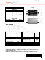
GM10-50B
PRODUCT NO:700-1000
GM10-50B
10kHz 50ns Gating Module
The GM10-50 module is a +5V d.c. powered 250V
pulse amplifier for periodic operation of MCP
devices by biasing the Cathode on and off for
specific lengths of time.
This unit requires an external +5V/200mA power supply and +5V TTL input trigger pulse.
The GM10-50 is designed to gate 25mm and 40mm Image Intensifier devices with
approximate capacitance between Cathode and MCPIN of 40-100pf.
The output pulse is directly related to the input pulse but will be delayed by approximately
120ns.
There is a pulse width loss across the GM10-50 between 10 and 30ns.
Operating Characteristics
The gate module is intended to connect directly to the cathode and MCP input of the device
being gated by a short length of wire.
The cathode is biased at +50V nominal with respect to the first MCP and the detector is
normally off (MCP In potential = 0V).
Activation of the gate module will drive the cathode –200V nominal. w.r.t. MCP In and thus
turn the detector on.
The gate pulse drive required is 5V TTL. The GM 10-50 has an input impedance of 4k7.
The propogation delay across the GM10-50 can be as much as 120ns, this is specific to each
unit and if precise figures are required the unit must be measured.
The input pulse to output pulse relationship of the GM10-50 is illustrated below: GM10-50 Pulse Characteristics
Input Pulse
Output Pulse
Pulse Width Loss
Propagation Delay
O/P Pulse Falltime
O/P Pulse Risetime
Off Voltage
On Voltage
Minimum
60-80ns
50ns
10ns
100ns
30ns
30ns
40V
180V
Maximum
D.C.
D.C.
30ns
120ns
50ns
50ns
50V
200V
User Manual
Issue:
Date:
Author:
UMGM10-50B
2
12-7-2010
P Simpson
GM10-50B
PRODUCT NO:700-1000
GM10-50 Connectors
SMB Socket
Input Power
Center
Screen
+5V
0V
SMA Socket
Input Signal
Center
Screen
TTL Pulse
0V
SMA Socket
Output Signal
Center
Screen
HT Pulse
0V
Items Supplied
1 off
1 off
1 off
1 off
GM 10-50B Gating Module.
Signal Cable – 1m BNC to SMA.
Power Cable – 1m SMB to Bare Ends.
UMGM10-50 – GM10-50 Operating Notes
Electrical Specifications - Inputs
Electrical Specifications - Outputs
Supply Voltage
Supply Voltage Absolute Max
Supply Current Maximum
(Operating Frequency = 10kHz)
Input Drive Pulse
Input Impedance
+5V D.C. ±10%
+5.5V D.C
200mA
Negative O/P Voltage Max.
Positive O/P Voltage Max.
Output Current Max.
-200V
+50V
3mA
5V TTL
4.7kΩ
Output Pulse Min.
Output Load Max.
Jitter (Input to Output )
Operating Frequency Max.
Operating Frequency Min.
50ns FWHM
100pF
<10ns
10kHz
D.C.
Mechanical Specifications
Length
Length (Incl. Connectors)
Width
Height
Weight
53.25mm
70.0mm
35.0mm
28.5mm
67g
Operating Temperature Range
Temperature Minimum
Temperature Maximum
0°C
70°C
© Photek Ltd. July 2010
Any unauthorised adjustment or modification to this unit will void all warranties and will only be
supported at Photeks discretion.
Photek reserves the right to amend general information contained in this manual without prior notice.
User Manual
Issue:
Date:
Author:
UMGM10-50B
2
12-7-2010
P Simpson