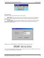
1
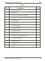
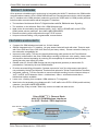
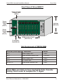
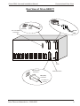
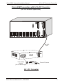
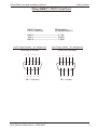
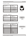
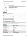
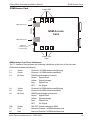
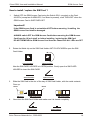
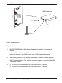
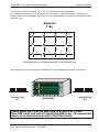
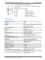
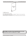
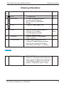
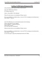
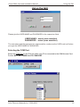
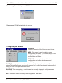
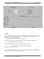
ORION TELECOM NETWORKS INC.
Orion-T1-GSM-72
72 - SIM, T1 GSM Gateway
User & Installation Manual
Orion Telecom Networks Inc.
16810, Avenue of Fountains, Suite # 108,
Fountain Hills,
AZ 85268 USA
PH: (+1) 480-816-8672, FAX: (+1) 480-816-0115
E-mail: [email protected]
Web Site: http://www.oriontelecom.com
Orion Telecom Networks Inc., 2000-2003
Orion-GSM, User and Installation Manual
Warranty
This Orion product is warranted against defects in material and workmanship for a period of
one year from date of shipment. During the warranty period, Orion will, at its option, either repair
or replace products which prove to be defective. For warranty service or repair, this product
must be returned to a service facility designated by Orion. Buyer shall prepay shipping charges
to Orion and Orion shall pay shipping charges to return the product to Buyer. However, Buyer
shall pay all shipping charges, duties and taxes for products returned to Orion from another
country.
Limitation of Warranty
The foregoing warranty shall not apply to defects resulting from improper or inadequate
maintenance by Buyer, Buyer-supplied firmware or interfacing, unauthorised modification or
misuse, operation outside of the environmental specifications for the product, or improper site
preparation or maintenance.
Exclusive Remedies
The remedies provided herein are the Buyer’s sole and exclusive remedies. Orion shall not be
liable for any direct, indirect special, incidental, or consequential damages, whether based on
contract, or any legal theory.
Notice
This manual contains information that is proprietary to Orion Telecom Networks Inc. No part of
this publication may be reproduced in any form whatsoever without prior written approval by
Orion Telecom Networks Inc.
Safety Warnings
!
The exclamation point within a triangle is intended to warn the operator or service
personnel of operation and maintenance factors relating to the product and its
operating environment which could pose a safety hazard.
Always observe standard safety precautions during installation, operation and maintenance of
this product. Only a qualified and authorized service personnel should carry out adjustment,
maintenance or repairs to this instrument. No adjustment, maintenance or repairs should be
performed by either the operator or the user.
CAUTION
ELECTROSTATIC
SENSITIVE
DEVICES
DO NOT OPEN OR HANDLE
EXCEPT AT A
STATIC-FREE WORKSTATION
Orion Telecom Networks Inc., 2000-2003
2
Orion-GSM, User and Installation Manual
Index
INDEX
S No
Particulars
Pg. No.
1.
Product Overview
4
2.
Front View
5
3.
Rear View and Connection Details
6
4.
Backpanel Connection with AC to DC Converter
7
5.
Cabling Details
9
6.
Pinout Details
10
7.
Shelf Description
12
8.
Installing SIM Card
14
9.
Installing Antenna
16
10.
T1 Interface Card
18
12.
T1 Echo Canceller Dummy Card
20
13.
Ordering Information
21
14.
Installing the GUI
22
15.
Using the GUI
23
16.
Support
27
Orion Telecom Networks Inc., 2000-2003
3
Orion-GSM, User and Installation Manual
Product Overview
PRODUCT OVERVIEW
Orion presents a breakthrough in technology by integrating the WAN T1 interface to the GSM mobile
communications network. Orion’s GSM Channel bank is a compact wireless solution, which integrates
the T1 interface to the GSM (wireless) network to provide the USER with 24, GSM (mobile) wireless
links for mobile communications with an integrated T1 Interface.
! The interface of the Network Side is T1 Digital Interface with D4, E&M wink-start Signaling.
! The interface on the Wireless Side is 24 x GSM Wireless links.
! Ideal choice for terminating long distance traffic / VoIP / VoFR or DCME traffic to the PSTN /
GSM (mobile cellular) networks. No LAND LINES REQUIRED!
! Remote monitoring and configuration through TCP/IP access.
! Unique out-bound calling, user programmable, access feature.
FEATURES & HIGHLIGHTS
!
Compact, 24 GSM wireless terminals in a 19-inch chassis.
!
GSM is integrated to the T1 Interface. No gray areas of what will work with what. Tested to work
with Cisco 3600 and Cisco 5300 VoIP Servers (and many others). Please contact the factory for
the exhaustive compatibility list.
!
Improved voice quality. The two wire trans-hybrid analog path (present in the Fixed Wireless
terminals) is eliminated in the Orion GSM design resulting in improved voice quality, clearer voice
and superior channel separation by reducing the susceptibility to echoes that result from the
analog two wire trans-hybrid VF paths.
!
Disable caller ID. Orion's GSM terminal can be programmed (operator) to block caller ID
presentation, if allowed by the local GSM Network.
!
Provides accurate billing information ("answer supervision" and "line disconnect supervision") not provided by Nokia Fixed Wireless Terminals and optional in Telular Fixed Wireless Terminals.
!
Integrated, optional, T1 Echo-Canceller to cancel echo-tails resulting from the inherent delays of
VoIP, VoATM, VoFR Networks. 64ms - unidirectional, 128ms - unidirectional and 64ms bidirectional options available.
!
Lower cost - resulting from complete, GSM wireless to T1 integration.
!
Ideal choice for terminating long distance traffic / VoIP traffic to the PSTN / GSM (mobile cellular)
networks. No LAND LINES REQUIRED!
!
Plug-And-Play. Easy to install. Takes only minutes to install and start service.
TM
Orion-GSM T1, Channel Bank
with 24 X GSM Wireless Interfaces
for VoIP / Switch / PBX Application
VoIP Server / Switch
/ PBX
D4, E&M
Wink-Start
24, GSM Wireless Terminals
Dial In
Dial Out
T1, GSM
Channel Bank
Orion Telecom Networks Inc., 2000-2003
4
Orion-GSM, User and Installation Manual
Front View
Front View of Orion-GSM-T1
Echo Canceller
Dummy Card
(Slot 2)
T1 GSM
Channel Bank
Power
Supply
Card
(Slot 1)
Power
Supply
Card
(Slot 3)
6U High
(265 mm)
GSM Interface Cards
(Slot 5 to 16)
T1 Interface
Card (Slot 4)
Slot Assignment of ORION-GSM
Front View (Left to Right)
Card Details
Part No.
Slot 1:
Power Supply Card
T1-010
Slot 2 :
Echo Canceller Dummy Card
T1-Dummy
Slot 3:
Power Supply Card
T1-010
Slot 4:
T1 Control Card
T1-015
Slot 5 to 16 :
GSM Access Interface Card
T1-072
Please Make sure that you have inserted the Echo Canceller
Dummy Card in order to complete the T1 Signal.
Orion Telecom Networks Inc., 2000-2003
5
Orion-GSM, User and Installation Manual
Connectorised Rear View
Rear View of Orion-GSM-T1
RJ-45
(Female)
RJ-45
(Male)
T1
Interface
-48VDC
TCP / IP Module
Connection
GND
Earth
DB9 (Female)
Connector
Alarm Extension
DB9 (Male)
Connector
To COM Port
(To PC)
Orion Telecom Networks Inc., 2000-2003
6
Orion-GSM, User and Installation Manual
AC to DC Converter Connection
Orion-GSM Connection with AC to DC Converter
(for AC Mains Operation)
-48 VDC
Input
-48 V DC
OUTPUT
TO 263
INPUT 97 V AC
47 HZ TO 63 HZ
V AC
3 Pin (male)
Socket
(for AC Mains Input)
From AC Source
AC - DC Converter
Orion Telecom Networks Inc., 2000-2003
7
Orion-GSM, User and Installation Manual
AC to DC Converter Specifications
Specifications: AC - DC Converter (for AC main operation)
Voltage - Input (VAC)
(85~132VAC, 170~264VAC, 47Hz - 63Hz)
Frequency
47~63Hz
Efficiency
82%typ
Inrush Current
30A typ (ACIN 100/200, lo=100%) (at cold start)
Leakage Current
0.75mA max (60Hz, according to UL,CSA, VDE
And DENTORI)
Voltage - Output
[VDC]
48VDC
Current
[A]
3A (Cumulative )
Line Regulation
[mV]
192 max
Load Regulation
[mV]
240 max
Ripple
0~+50 °C
150 Max
-10-0 °C
200 max
0~+50 °C
400 Max
-10-0 °C
600 max
Temperature
[mV]
560 max
Coefficient Drift
[mV]
192 max
Start-Up time
[mS]
200 max (ACIN 100V, lo=100%)
Hold- Up time
[mS]
10 typ (ACIN 85V, lo=100%), 20 typ (ACIN 100V,
[mVp-p]
Ripple Noise
[mVp-p]
lo=100%)
Output Voltage
[V]
Overcurrent Protection
Fixed -48VDC
Works over 105% of rating (-H:peak) and recovers
automatically .Additional protection is provided by a
4Amps slow-blow fuse.
Overvoltage Protection
Works at 105% ~ 140% of rating
Input- Output
AC3,000V, 1minute cutoff current= 10mA, DC500V,
50MW min. (At room temperature)
Input-FG
AC2,000V, 1minute cutoff current= 10mA, DC500V,
50MW min. (At room temperature)
Output-FG
AC500V, 1minute cutoff current= 10mA, DC500V,
50MW min. (At room temperature)
Operating Temp. And Humid.
-10~+60 °C, 20~90%RH (Non-condensing)
Strage Temp. And Humid.
-20~+75 °C, 20~90%RH (Non-condensing)
Vibration
10~55Hz, 2G, 3min. Period, 60 min. each along X, Y
and Z axis.
Impact
20G, 11mS, once each X, Y and Z axis.
Safety
Recognized UL 1950, approved En60950, certified
CSA C22.2 No.234, compiles with DENTORI and
IEC950
Conducted Noise
Orion Telecom Networks Inc., 2000-2003
Compiles with FCC-B, Vfg2443/91 and VCCI 2
8
Orion-GSM, User and Installation Manual
Cabling Details
Orion-GSM-T1 TO PC Com Port
DB-9F (Female)
(To PC COM Port)
DB-9M (Male)
(To ORION-GSM-T1)
RXD 2 ------------------------------------- 2 TXD
TXD 3 ------------------------------------- 3 RXD
GND 5 ------------------------------------ 5 GND
9 pin D-type (female) - pin assignment
9 pin D-type (male) - pin assignment
(View from front side)
(View from front side)
5
3
4
9
8
2
7
1
6
DB - 9 (female)
Orion Telecom Networks Inc., 2000-2003
1
2
6
3
7
4
8
5
9
DB - 9 (male)
9
Orion-GSM, User and Installation Manual
Pinout Details
RJ-45 for T1 Input
RJ-45 (male)
Pin #
Signal in
RJ-45 (male)
1
Tx Tip (Data Out)
2
Tx Ring (Data Out)
4
Rx Tip (Data In)
5
Rx Ring (Data In)
1 234 5 6 7 8
RJ-45
(Female)
RS232 DB-9 - NMS Port
DB-9 (female)
Pin #
Signal in
DB-9 (female)
2
Transmit (Data Out)
3
Receive (Data In)
5
Ground
DB-9
(Female)
DB-15 - Connection to TCP-IP Access Module
DB-15 (female)
Pin #
Signal in
DB-15 (female)
1
+5V
2
+5V
9
+5V
12
TXD
13
RXD
7
GND
8
PWR GND
15
PWR GND
Orion Telecom Networks Inc., 2000-2003
DB-15
(Female)
10
Orion-GSM, User and Installation Manual
Installing the GSM Equipment
Installing the GSM Equipment
Precautions:
1
a) ALWAYS SWITCH OFF the GSM Access Card before removing it from the
Chassis.
b) The GSM Access Card may be SWITCHED OFF by pressing the push- button
switch SW1 till the LED’s turn OFF.
c) Ejecting / Removing the GSM Access Card or disconnecting power from 19-Inch
shelf without SWITCHING OFF the GSM Access Card may result in permanent
damage to the GSM Transceiver / GSM Access Card.
2.
ALWAYS ensure that the ANTENNAS are connected to the GSM Transceiver / GSM
Access Card before they are powered-up.
Any GSM Transceiver POWERED-UP without an ANTENNA may be damaged
permanently.
3.
ALWAYS ensure that the ANTENNA connector is properly connected (snapped-in)
to the GSM Transceiver Module (GSM Access Card).
4.
ALWAYS insert the SIM Cards FACE UP in the SIM Card Tray and ensure that the
SIM Card Tray is firmly locked into its place after the SIM Card has been inserted /
Replaced.
5.
NEVER INSERT / REPLACE the SIM Card with the GSM Access Card is POWERON position.
SIM Cards should be inserted / replaced only after removing the GSM Access Card
From the 19-inch shelf.
The GSM Access Card / GSM Transceivers should be SWITCHED-OFF (using the
push-button SW1).
Before removing the GSM Access Card from the shelf.
IMPORTANT !!
It is NOT ESSENTIAL for the USER to shut-down the complete system to replace / insert
NEW SIM CARDS. Each GSM Access Card may be SWITCHED OFF INDEPENDENTLY to
REPLACE / INSERT a NEW SIM CARD, without shutting-down the entire system.
The GSM Access Card may be switched INDEPENDENTLY using the push-button switch
SW1. The Card should be removed from the chassis after ALL LEDs are OFF.
Orion Telecom Networks Inc., 2000-2003
11
Orion-GSM, User and Installation Manual
Shelf Description
Shelf Description
Power
Supply
Card
PSU Front Indications
The PSU provides the following indications in the front of the sub-rack:
3 LEDs which indicate the following:
L1 - Positive 5V present
L2 - Negative 48V present
Description:
PS, Power Supply Card Part # T1-010
Each ORION-GSM 19-inch shelf has two PSU, Power Supply Cards Part # ORION-GSM010.
The ORION-GSM Power Supply Card plugs into slot # 1 and slot # 3 of the ORION-GSM,
19-inch shelf. (Please see figure on page 5).
It converts -48VDC Input (-40VDC to -60VDC Input) and provides +5VDC output that is
required for the functioning of the equipment.
The PS, Power Supply Card has two LEDs.
LED L1 indicates the presence of -48VDC input.
LED L2 indicates the presence of +5VDC output.
The card is protected against accidental reverse polarity of the -48VDC input, and shall only
function if the -48VDC input is connected with the correct polarity.
Specifications
Input DC voltage
Range of input
Output voltages
Full Load Output Current
Input Voltage Reversal Protection
Over Current Protection
Short Circuit Protection
Under Voltage
Over Voltage
Efficiency at full load
Ripple at full load
Spike at full load
Power Consumption
-48V DC ( nominal )
-40V to -60V DC
+5V
18A@5VDC
Provided in the Card
20A for +5V
Current limit - 20A. Recovers on removal of short
< 4.5V
5.4V to 5.6V
>80%
<5mVrms
<50mV
120 Watts (Worst Case)
Orion Telecom Networks Inc., 2000-2003
12
Orion-GSM, User and Installation Manual
GSM Access Card
GSM Access Card
Insert SIM
Here
L8
L7
Switch
GSM Transceiver
L6
L5
L4
L3
L2
L1
GSM Access
Card
GSM Transceiver
COM Port
Connector for
Programming
Insert SIM
Here
GSM Interface Card Front Indications
The T1 Interface Card provides the following indications in the front of the sub-rack:
LEDs which indicate the following:
L1
Yellow
Channel 1 of GSM interface card Ringing
L2
Green
Channel 1 of GSM interface card Busy
L3
Bi-Color
GSM Signal strength of channel 1
Green: Signal Good
Yellow: Signal Average
Red:
Signal Poor
OFF:
No Signal
L4
Yellow
Channel 2 of GSM interface card Ringing
L5
Green
Channel 2 of GSM interface card Busy
L6
Bi-Color
GSM Signal strength of channel 2
Green: Signal Good
Yellow: Signal Average
Red:
Signal Poor
OFF:
No Signal
SW
Switch
ON / OFF for both channel of GSM
L7
Red
Alarm on Channel 1 of GSM interface card
L8
Red
Alarm on Channel 2 of GSM interface card
Orion Telecom Networks Inc., 2000-2003
13
Orion-GSM, User and Installation Manual
GSM Access Card
How to install / replace the SIM Card ?
1.
Switch OFF the GSM Access Card using the Switch SW-1 mounted on the Card.
All LED’s (except an ALARM LED, if an alarm is present), shall TURN-OFF when the
GSM Access Card is SWITCHED-OFF.
Important!!
If the GSM Access Card is not switched OFF before removing / installing the
GSM Access Card shall be damaged.
ALWAYS switch OFF the GSM Access Card before removing the GSM Access
Card from the 19 inch shelf, or before installing / replacing the SIM Card.
DO NOT REMOVE the GSM Access Card from the Chassis till ALL LEDs are OFF
2.
Rotate the Metal clip on the SIM Card Holder ANTI CLOCK WISEto open the SIM
Card Holder
Close Position
Open Position
Now the SIM CARD HOLDER is in OPEN position. Gently open the SIM CARD
HOLDER to insert the SIM CARD
Close Position
3.
Slide the SIM Card in the slot of the tray of SIM Card Holder, with the metal contacts
Face up.
Notch
SIM Card
4.
Open Position
Notch
SIM Card Holder
SIM Card Holder
Now close the SIM Card Holder and make sure it is closed completely.
Open Position
Orion Telecom Networks Inc., 2000-2003
Close Position
14
Orion-GSM, User and Installation Manual
5.
GSM Access Card
Gently press down and rotate the Metal clip on the SIM Card Holder CLOCK WISE till
the metal clip is locked under the plastic in the closed position.
Open Position
Close Position
6.
Insert ALL SIM Cards in their respective SIM Holders in this manner.
7.
Insert the GSM Access Card into the Chassis, gently but firmly till the card is fully
seated.
An alarm shall be displayed in LED L1 / L2 for the following reasons
1.
Invalid SIM Card
2.
Unregistered SIM Card
3.
Faulty SIM Card
4.
Faulty GSM Module
5.
GSM Access Card Out of Range
Specifications: GSM Access Card
Number of GSM Interfaces
Type
Compliance
Approvals
SIM Interface Internal Tray
Voice Features
DTMF
1 ~ 24 (Stackable, 1 thru 24).
Dual Band EGSM 900 MHz
and EGSM 1800 MHz.
Compliant with ETSI GSM
Phase 2+ standard (Normal MS)
Class 4 (2W @ 900MHz)
Class 1 (1W @ 1800 Mhz)
Fully Type Approved to GSM
Standards
Toolkit Class 2.
3V Reader
Full Rate, Enhanced Full Rate
And Half-Rate (FR/EFR/HR)
Dual Tone Multi FrequencyFunction (DTMF)
Dialing Support
Orion Telecom Networks Inc., 2000-2003
15
Orion-GSM, User and Installation Manual
L8
L7
Installing Antenna
GSM Transceiver
Switch
L6
L5
L4
L3
L2
L1
GSM
Access
Card
Antenna Connector
Socket
Antenna
How to install Antenna ?
Important !
1.
NEVER POWER-ON the GSM Access Card without installing / connecting the
Antenna.
Switching ON a GSM Access Card without connecting it to an Antenna may result in
permanent damage to the GSM Access Card / GSM Transceiver module.
2.
Snap-on the connector of the antenna to the GSM Transceiver module antenna
Connector. Please ensure that the antenna connector is connected properly to the
GSM Transceiver Module. The antenna connector snaps in to connect to the GSM
Transceiver module.
3.
(a)
(b)
L1 RED LED indicates Alarm on GSM Card Channel 2 (Alarm)
L2 RED LED indicates Alarm on GSM Card Channel 1 (Alarm)
Orion Telecom Networks Inc., 2000-2003
16
Orion-GSM, User and Installation Manual
Installing Antenna
Two Antenna Tray each sized 18” X 12” are provided with the equipment.
It is advisable to place only 12 antennas on each tray in order to minimize interference.
Please use the recommended layout given in the figure below, to place the antennas on the
Antenna Tray.
Antenna
Tray
1”
2”
2”
2”
2”
X
X
4”
4”
4”
4”
1”
X
X
4”
1”
X
2”
4”
5”
4”
5”
2”
2”
2”
4”
5”
2”
X
2”
2”
Typical placement of external antennas on the Antenna Tray
T1 GSM
Channel Bank
One antenna tray should be placed either side of the equipment as shown in the figure:
Antenna Tray
#1
ORION-GSM
Antenna Tray
#2
Please Make sure that the SIM Card is in use is of 3 Volts
(New SIM Card) and not of 5 Volts(Old SIM Card). The equipment
does not accept and work with 5 Volt Sim Cards.
Orion Telecom Networks Inc., 2000-2003
17
Orion-GSM, User and Installation Manual
L1
L2
L3
L4
L5
L6
T1
Interface
Card
T1 Interface Card
T1 Control Card (CC1) Front Indications
The T1 Interface Card provides the following indications in the front
of the sub-rack:
LEDs which indicate the following:
L1 Green
SYNC
L2 Red
(LOS) Loss of Signal
L3 Red
(LOF) Loss of Frame
L4 Red
(LOMF) Loss of Multiframe
L5 Red
(RA) Remote Alarm
L6 Red
(AIS) Alarm Indication Signal
Specifications
Number of T1 Interfaces
Conformity
Framing
Signaling
PCM Sampling Rate
Encoding Law
Bit Rate
Code
Nominal Impedance
Connector
Peak Voltage of a mark
For 100 Ohms Balanced Interface
Pulse Mask
Output Jitter
Permissible Attenuation
Return Loss at:
51.2 KHz to 102.4 KHz.
102.4 KHz to 2048 KHz
2048 KHz to 3072 KHz
Jitter Tolerance
Loss and Recovery of Frame Alignment
One
G.703
D4
D4, Robbed-Bit , E&M Wink-Start Signaling
with answer supervision
8000 samples / second.
Mu Law
1544Kbps 50ppm.
AMI, B8ZS - Selectable
100 Ohms Standard
(75 Ohms Optional)
RJ45 (100 Ohms Impedance)
3.0 Volt 0.3 Volt.
As per ITU-T (CCITT) Rec. G.703
<0.05UI (in the frequency range
of 20Hz to 100KHz).
6dB at 1MHz
> 12dB
> 18dB
> 14dB
As per ITU-T (CCITT) G.823
As per Clause 3 of ITU-T
(CCITT) G.732
Loss and Recovery of Multi-Frame Alignment As per Clause 5.2 of ITU-T
(CCITT) G.732
Orion Telecom Networks Inc., 2000-2003
18
Orion-GSM, User and Installation Manual
Setting for T1 Interface
Setting of T1 Interface of your Router
Framing
Signaling
Encoding Law
Code
D4
D4, Robbed-Bit , E&M Wink-Start Signaling
with answer supervision
Mu Law
AMI, B8ZS - Selectable (prefer B8ZS)
Orion Telecom Networks Inc., 2000-2003
19
Orion-GSM, User and Installation Manual
Echo Canceller Dummy Card
Echo Canceller
Dummy
Card
T1-GSM Dummy Card
The T1-Dummy Card has no LEDs.
The T1-Dummy Card is used in order to complete the T1 Signal. It is to be inserted if the
Echo Canceller card is not being used.
Please see page # 5 for the slot where the Echo Canceller Dummy Card is to be inserted.
Please Make sure that you have inserted the Echo Canceller
Dummy Card in order to complete the T1 Signal.
Orion Telecom Networks Inc., 2000-2003
20
Orion-GSM, User and Installation Manual
Ordering Information
Ordering Information
1.
2.
3.
Common Equipment
Sr.
No.
Part No.
T1-015
T1-000 / 005
T1-010
4.
T1-072
5.
T1-024-ANT
6.
T1-01048-150W
Product Description
Qty
T1 Control Card
19" Shelf 3U High (Sub-rack) to
accommodate 24 Channels
with Connectorized Backplane
6U High
(-) 48VDC Power Supply Card
01
01
Dual Port Access Card to connect to
connect to an T1interface,
12 Cards (max) per system
3 SIM per GSM Channel
External Antennas Connectorized
Cable (2 meters)
Power Supply (External) AC to DC
Converter Portable External Converter
Universal AC Input [93VAC-276VAC,
47Hz-63Hz] to DC Output [(-) 48VDC]
02
12
(max.)
24
01
Optional
7.
TCP-IP-MSS100
TCP-IP-MSS100 ethernet remote access
01
module for configuration option allows the
user to access, configure and control the T1
Channel Bank equipment over a TCP-IP
network. 1 Required for every T1 Shelf
Orion Telecom Networks Inc., 2000-2003
21
Orion-GSM, User and Installation Manual
Installing GUI
Installing T1-GSM, System Management GUI.
(Use with Windows 98, Windows 2000 and WindowsXP).
Insert CD- ROM into the CD drive.
CD- ROM is autorun CD.
Click on “Orion-GSM-T1 GUI Software”
Follow the instructions on the Installation Software screen.
Now your installation is completed and you can run GUI for managing and configuring the
Orion-GSM-T1, Terminal.
If the CD- ROM does not run automatically please do the following:
Click on Start Menu of your computer
Go to Programs ----> Windows Explorer
Click on your CD Drive.
Go to GUI folder click on setup.exe
Follow the instructions on the Installation Software screen.
Now your installation is completed and you can run GUI for managing and configuring the
Orion-GSM-T1, Terminal.
You can also print or copy the User Manuals from the CD- ROM
Orion Telecom Networks Inc., 2000-2003
22
Orion-GSM, User and Installation Manual
Using the GUI
Using the GUI
orion
orion
Please give the USER NAME and PASSWORD in the respective fields
USER NAME : orion (case sensitive)
PASSWORD : orion (case sensitive)
The user name and the password are case sensitive, make sure the CAPS lock is off when
you type the USER NAME & PASSWORD.
Selecting the COM Port
Select the COM Port (in the GUI) on which your PC is connected to the GSM Access Card.
For this GO to SETTINGS then PC COM PORT
Orion Telecom Networks Inc., 2000-2003
23
Orion-GSM, User and Installation Manual
Using the GUI
Downloading after selecting correct COM Port
Downloading if COM Port selection is incorrect.
Configuring the System
File Menu
File menu consists of the following menu items:NEW - This menu is used for making a new
configuration and status . On clicking NEW , a form
is displayed through which a user can define a new
configuration and status.
OPEN - This menu option is used to retrieve
configuration and status which was saved
previously.
SAVE - This menu option is used to save the currently displayed system configuration and
status. This is effective only once the file name of the system has already been specified
using the SAVE AS option described next.
SAVE AS - This menu option is used to save the currently displayed configuration and
status with a user assigned file name.
Exit -This menu is used for exiting the configuration and status .
Orion Telecom Networks Inc., 2000-2003
24
Orion-GSM, User and Installation Manual
Using the GUI
T1-GSM
The T1-GSM GUI helps in configuring the T1-GSM system through a serial port connection
between the T1-GSM eqipment and a PC. It also lets the user view the status of the
individual channels in T1-GSM system.
The control parameters that can be configured are Line Coding:- AMI/B8ZS Framing:-D4/SF/F12 Clock:-INTERNAL/LOOP-TIMED
The status parameters that can be viewed are SIGNAL STRENGTH (GSM signal strength for individual channel)
FAULT/OFF (Channel module faulty or powered off)
STATUS (Channel Idle or Busy)
In case the particular channels are unequipped, the system will display unequipped status
instead of the above mentioned status parameters.
Orion Telecom Networks Inc., 2000-2003
25
Orion-GSM, User and Installation Manual
Using the GUI
Administration
This menu consists of the following sub menu options.
1.
NEW USER - This menu option is used for adding a new user for the application.
This option remains disabled until the super user logs by using the Super User option
described next.
2.
SUPER USER- This menu option is used to log in the super user. Only the super
user has the privilege to create new user. The super user must enter the login id &
password as shown below
addm
addm
Please give the USER NAME and PASSWORD in the respective fields
USER NAME : addm (case sensitive)
PASSWORD : addm (case sensitive)
The user name and the password are case sensitive, make sure the CAPS lock is off when
you type the USER NAME & PASSWORD.
Orion Telecom Networks Inc., 2000-2003
26
Orion-GSM, User and Installation Manual
Support
Notes :
Technical specification are subject to change without notice.
Windows is the registered Trademark of Microsoft Corporation, USA.
Revision 05. 30th September 2003.
Orion Telecom Networks Inc.
16810, Avenue of Fountains, Suite # 108,
Fountain Hills,
AZ 85268 USA
PH: (+1) 480-816-8672, FAX: (+1) 480-816-0115
E-mail: [email protected]
Web Site: http://www.oriontelecom.com
Orion Telecom Networks Inc., 2000-2003
27