1
Configuring Support for PBX Signalling Protocols
This chapter describes how to configure support for PBX signalling formats such as Q.SIG and
transparent common channel signalling (CCS). Configuring support for these signalling protocols on
your router enables the router to interoperate with PBXs running these signalling protocols.
This chapter includes the following sections:
•
Configuring Q.SIG PRI Signalling Support
•
Configuring Transparent CCS on the Cisco MC3810
For a complete description of the commands used in this chapter, refer to the Cisco IOS Multiservice
Applications Command Reference. To locate documentation of other commands that appear in this
chapter, use the command reference master index or search online.
Configuring Q.SIG PRI Signalling Support
Configuration Tasks for Q.SIG PRI signalling support are described in the following sections:
•
Configuring Voice over IP Q.SIG Network Transparency on the Cisco AS5300
•
Configuring Q.SIG PRI Signalling Support on the Cisco MC3810
Although the procedures for configuring Q.SIG signalling support on the Cisco AS5300 and on the
Cisco MC3810 are very similar, implementation differences are described in the respective sections.
Benefits of Q.SIG
On both the Cisco AS5300 and the Cisco MC3810, Q.SIG voice signalling provides the following
benefits:
•
Enables Cisco devices to connect with digital PBXs that use the Q.SIG form of CCS.
•
Provides access to multiple remote PBXs with a single connection to a Cisco device.
•
Provides transparent support for supplementary PBX services, so that proprietary PBX features are
not lost when connecting PBXs to Cisco AS5300 and Cisco MC3810 networks.
•
Provides Q.SIG support based on widely used ISDN Q.931 standards. Cisco Q.SIG implementation
follows the following European Telecommunications Standards Institute (ETSI) implementation
standards:
– ECMA 143: Private Telecommunication Network (PTN) Inter-exchange Signalling Protocol
Circuit Mode Basic Services. (This specification covers Q.SIG basic call services.)
Cisco IOS Multiservice Applications Configuration Guide
MC-413
Configuring Support for PBX Signalling Protocols
Configuring Q.SIG PRI Signalling Support
– ECMA 142: Specification, Functional Model and Information Flows for Control Aspects of
Circuit Mode Basic Services in Private Telecommunication Networks.
– ECMA 141: Private Telecommunications Networks Inter-exchange Signalling Data Link Layer
Protocol.
– ECMA 165: Generic Functional Protocol for the Support of Supplementary Services.
•
Provides compatibility with H.323 for IP call setup and transport of Q.SIG messaging.
•
Provides support for calls that do not require a bearer channel for voice transport.
•
Provides support for bandwidth-on-demand, utilizing network resources only when a connection is
desired.
Configuring Voice over IP Q.SIG Network Transparency on the Cisco AS5300
Integration of Q.SIG support with VoIP enables Cisco voice switching services to connect PBXs, key
systems, and CO switches that communicate by using the Q.SIG protocol.
In Cisco IOS Release 12.1, Q.SIG PRI signalling on the Cisco AS5300 applies only to VoIP.
The Q.SIG protocol is a variant of ISDN D-channel voice signalling. It is based on the ISDN Q.921 and
Q.931 standards and is becoming a worldwide standard for PBX interconnection. By using Q.SIG
signalling, Cisco devices can route incoming voice calls from a private integrated services network
exchange (PINX) device across a WAN to a peer Cisco device, which can then transport the signalling
and voice packets to a second PINX device.
Note
In Cisco IOS Release 12.1, the Cisco AS5300 supports ISDN PRI only when a Q.SIG
connection to the PINX is configured on the T1/E1 controller.
Q.SIG allows the user to place Q.SIG calls into and receive Q.SIG calls from Cisco VoIP networks. The
Cisco packet network appears to PBXs as a large, distributed transit PBX that can establish calls to any
destination served by a Cisco voice node. The switched voice connections are established and torn down
in response to Q.SIG control messages that come over an ISDN PRI D channel. The Q.SIG message is
passed transparently across the IP network and the message appears to the attached PINX devices as a
transit network. The PINX devices are responsible for processing and provisioning the attached services.
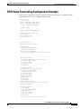
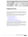
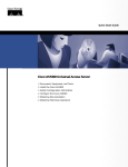
Figure 96 shows an example of a Q.SIG signalling configuration. In this example, the Cisco AS5300 acts
as either a master to a slave PBX or as a slave to a master PBX.
Cisco AS5300 Q.SIG Signalling Configuration
PBX
3001
Q.SIG
E1/T1 channel
Slave
Cisco
AS5300
No. 1
IP
Master
Cisco
AS5300
No. 2
Slave
Q.SIG
E1/T1 channel
PBX
4001
Master
22864
Figure 96
The following restrictions and limitations apply to the Cisco AS5300 Q.SIG implementation:
•
Q.SIG functionality on the AS5300 requires Cisco IOS Release 12.0(7)T or later and VCWare
version 4.04.
Cisco IOS Multiservice Applications Configuration Guide
MC-414
Configuring Support for PBX Signalling Protocols
Configuring Q.SIG PRI Signalling Support
•
Q.SIG data calls are not supported. All calls with bearer capability indicating a nonvoice type (such
as video telephony) are rejected.
•
The incoming POTS dial peer must have DID configured to prevent generation of a secondary dial
tone to ensure end-to-end Q.SIG feature transparency.
Q.SIG Prerequisite Tasks
The following configuration tasks should be completed before you configure Q.SIG for VoIP:
•
Configure the ports used on the Cisco AS5300 as voice ports. For information on how to configure
ports to be used as voice ports, see “Configuring Voice Ports” section in the “Configuring Voice over
IP” chapter.
•
Install VCWare version 4.04. For information on how to upgrade or install VCWare, see the
“Managing Cisco AS5300 VFCs ” section in the “Configuring Voice over IP” chapter.
•
Configure VoIP. For information on how to configure VoIP, see the “Configuring Voice over IP”
chapter.
Q.SIG Configuration Task List
To configure Q.SIG for Voice over IP, complete the tasks shown in the following sections. Some of these
tasks are optional.
•
Configuring VoIP Q.SIG
•
Configuring Fusion Call Control Signalling (NEC Fusion) on the Cisco AS5300
Configuring VoIP Q.SIG
To configure Q.SIG signalling support on the Cisco AS5300, use the following commands beginning in
global configuration mode:
Step 1
Command
Purpose
Router(config)# isdn switch-type primary-qsig
Configures the ISDN switch-type to support Q.SIG
signalling.
Note
You can configure the ISDN switch type
using either this global command or the same
command in interface configuration mode,
depending on your configuration. (See Step
5.) If you configure the global
isdn-switch-type command for Q.SIG
support, you need not configure the interface
isdn-switch-type command for Q.SIG.
If the PBX in your configuration is an NEC PBX, and
you are using Fusion Call Control Signalling (FCCS).
See the “Configuring Fusion Call Control Signalling
(NEC Fusion) on the Cisco AS5300” later in this
chapter.
Cisco IOS Multiservice Applications Configuration Guide
MC-415
Configuring Support for PBX Signalling Protocols
Configuring Q.SIG PRI Signalling Support
Command
Purpose
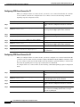
Step 2
Router(config)# controller {T1 | E1} controller
number
Enters controller configuration mode.
Step 3
Router(config-controller)# pri-group [timeslot
range]
Configures the PRI group for either T1 or E1 to carry
voice traffic. For T1, available time slots are from 1
to 23, and for E1, available time slots are from 1 to
31.
You can configure the PRI group to include all
available time slots, or you can configure a select
group of time slots for the PRI group. For example, if
only time slots 1 to 10 are in the PRI group, enter the
pri-group timeslot 1-10 command. If the PRI group
includes all channels available for T1 (channels 1 to
23), enter the pri-group timeslot 1-23 command. If
the PRI group includes all channels available for E1
(channels 1 to 31), enter the pri-group timeslot 1-31
command.
Step 4
Router(config-controller)# exit
Exits controller configuration mode.
Step 5
Router(config)# interface serial 1:x
Enters interface configuration mode for the ISDN
PRI interface. For T1, enter serial 1:23. For E1, enter
serial 1:15.
Step 6
Router(config-if)# isdn switch-type primary-qsig
If you did not configure the global ISDN switch type
for Q.SIG support in Step 1, configures the interface
ISDN switch type to support Q.SIG signalling.
The conditions that apply to this command in global
configuration mode also apply to this command in
interface configuration mode.
This interface command overrides the global isdn
switch-type command setting for this interface.
Step 7
Router(config-if)# isdn protocol-emulate {user |
network}
Configures the ISDN interface to serve as either the
primary Q.SIG slave or the primary Q.SIG master.
For this command, the user keyword specifies slave
and the network keyword specifies master.
If the PINX is the primary Q.SIG master, configure
the Cisco AS5300 to serve as the primary Q.SIG
slave. If the PINX is the primary Q.SIG slave,
configure the Cisco AS5300 to serve as the primary
Q.SIG master.
Step 8
Router(config-if)# isdn overlap-receiving value
Activates overlap signalling to send to the destination
PBX.
This command is not mandatory; you can leave the
default value.
Step 9
Router(config-if)# isdn incoming-voice modem
Cisco IOS Multiservice Applications Configuration Guide
MC-416
Routes incoming voice calls to the modem and treats
them as analog data.
Configuring Support for PBX Signalling Protocols
Configuring Q.SIG PRI Signalling Support
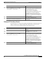
Step 10
Command
Purpose
Router(config-if)# isdn network-failure-cause
[value]
(Optional) Specifies the cause code to pass to the
PBX when a call cannot be placed or completed
because of internal network failures. Possible values
are from 1 to 127.
All cause codes except for Normal Call Clearing (16),
User Busy (17), No User Responding (18), and No
Answer from User (19) will be changed to the
specified cause code.
Step 11
Router(config-if)# isdn bchan-number-order
{ascending | descending}
(Optional) Configures the ISDN PRI interface to
make the outgoing call selection in ascending or
descending order.
The default is descending order, in which the first call
from the Cisco AS5300 uses channel 23 (T1) or
channel 31 (E1). The second call then uses channel 22
(T1) or channel 30 (E1), and so on in descending
order.
If you select ascending order and the PRI group starts
with 1, the first call uses channel 1, the second call
uses channel 2, and so on in ascending order. If the
PRI group starts with a different time slot, the
ascending order starts with the lowest time slot.
Step 12
Router(config-if)# exit
Exits interface configuration mode.
As shown in the preceding section, you have a choice of configuring the isdn-switch-type command to
support Q.SIG at either the global configuration level or the interface configuration level. For example,
if you have a Q.SIG connection on one line and on the PRI port, you can configure the ISDN switch type
in one of the following combinations:
•
Set the global isdn-switch-type command to support Q.SIG and set the interface isdn-switch-type
command for interface serial 0:23 to a PRI setting such as 5ess.
•
Set the global isdn-switch-type command to support PRI 5ess and set the interface
isdn-switch-type command for interface serial 1:23 to support Q.SIG.
•
Configure the global isdn-switch-type command to another setting (such as switch type VN3), set
the interface isdn-switch-type command for interface serial 0:23 to a PRI setting, and set the
interface isdn-switch-type command for interface serial 1:23 to support Q.SIG.
Configuring Fusion Call Control Signalling (NEC Fusion) on the Cisco AS5300
If you have an NEC PBX in your network and you are running FCCS, you will need to configure this
device appropriately. FCCS, also known as NEC Fusion, allows individual nodes anywhere within a
network to operate as if they were part of a single integrated PBX system. The database storage, share,
and access routine of NEC Fusion allow real-time access from any node to any other, allowing individual
nodes to “learn” about the entire network configuration. This capability allows network-wide feature,
functional, operational, and administration transparency.
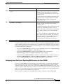
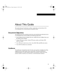
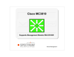
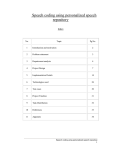
Figure 97 shows an example of an AS5300 Q.SIG signalling configuration using an NEC PBX.
Cisco IOS Multiservice Applications Configuration Guide
MC-417
Configuring Support for PBX Signalling Protocols
Configuring Q.SIG PRI Signalling Support
NEC
PBX
Q.SIG Signalling Configuration with NEC PBX
FCCS
T1 channel
Ethernet
signaling
Cisco
AS5300
IP
QoS
cloud
Cisco
AS5300
FCCS
T1 channel
Ethernet
signaling
NEC
PBX
28853
Figure 97
To configure NEC Fusion signalling support on the Cisco AS5300, use the following commands
beginning in global configuration mode:
Step 1
Command
Purpose
Router(config)# controller T1 controller number
Enters controller configuration mode.
NEC Fusion does not support fractional T1/E1; all
24 channels must be available. If they are not
available, the configuration request will fail.
Step 2
Router(config-controller)# pri-group nec-fusion
{pbx-ip-address/pbx-ip-host-name} pbx-port number
Configures the controller to communicate with an
NEC PBX using NEC Fusion.
The range for the PBX port is 49152 to 65535. If you
do not specify a port number, the default value of
55000 will be used. If this value is already in use, the
next greater value will be used.
Step 3
Router(config-controller)# exit
Exits controller configuration mode.
Verifying VoIP Q.SIG Software on the Cisco AS5300
After you complete the configuration for the AS5300, verify that you configured Q.SIG properly. Enter
the show isdn status command to view the ISDN layer information. The following output shows that
you have correctly designated the global ISDN switch type to be primary-Q.SIG.
router# show isdn status
Global ISDN Switchtype = primary-qsig
ISDN Serial1:23 interface
dsl 0, interface ISDN Switchtype = primary-qsig
**** Slave side configuration ****
Layer 1 Status:
DEACTIVATED
Layer 2 Status:
TEI = 0, Ces = 1, SAPI = 0, State = TEI_ASSIGNED
Layer 3 Status:
0 Active Layer 3 Call(s)
Activated dsl 0 CCBs = 0
The Free Channel Mask: 0x7FFFFF
Cisco IOS Multiservice Applications Configuration Guide
MC-418
Configuring Support for PBX Signalling Protocols
Configuring Q.SIG PRI Signalling Support
Q.SIG for VoIP Configuration Example
The following configuration example configures interface serial 1:23 for Q.SIG PRI and to act as the
Q.SIG slave:
!
version 12.0
service timestamps debug uptime
service timestamps log uptime
no service password-encryption
!
hostname as5300A
!
ip subnet-zero
!
isdn switch-type primary-qsig
!
controller T1 0
shutdown
!
controller T1 1
framing esf
clock source line primary
linecode b8zs
pri-group timeslots 1-24
!
controller T1 2
shutdown
!
controller T1 3
shutdown
!
!
voice-port 1:D
!
!
dial-peer voice 3001 pots
destination-pattern 3001
port 1:D
!
dial-peer voice 4001 pots
incoming called-number 4001
direct-inward dial
!
dial-peer voice 4002 voip
destination-pattern 4001
session target ipv4:1.14.82.14
!
!
interface Ethernet0
ip address 1.14.82.13 255.255.0.0
no ip directed-broadcast
!
interface 1:23
no ip address
no ip directed broadcast
isdn switch-type primary-qsig
isdn protocol-emulate user
isdn incoming-voice modem
!
interface FastEthernet0
no ip address
no ip directed-broadcast
Cisco IOS Multiservice Applications Configuration Guide
MC-419
Configuring Support for PBX Signalling Protocols
Configuring Q.SIG PRI Signalling Support
shutdown
!
ip default-gateway 1.14.0.1
ip classless
!
line con 0
transport input none
line aux 0
line vty 0 4
login
!
end
=====================================================
!
version 12.0
service timestamps debug uptime
service timestamps log uptime
no service password-encryption
!
hostname as5300B
!
ip subnet-zero
!
isdn switch-type primary-qsig
!
!
controller T1 0
shutdown
!
controller T1 1
framing esf
clock source line primary
linecode b8zs
pri-group timeslots 1-24
!
controller T1 2
shutdown
!
controller T1 3
shutdown
!
!
voice-port 1:D
!
!
dial-peer voice 3001 pots
incoming called-number 3001
direct-inward-dial
!
dial-peer voice 3002 voip
destination-pattern 3001
session target ipv4:1.14.82.13
!
dial-peer voice 4001 pots
destination-pattern 4001
port 1:D
!
interface Ethernet0
ip address 1.14.82.14 255.255.0.0
no ip directed-broadcast
!
interface Serial1:23
no ip address
Cisco IOS Multiservice Applications Configuration Guide
MC-420
Configuring Support for PBX Signalling Protocols
Configuring Q.SIG PRI Signalling Support
no ip directed-broadcast
isdn switch-type primary-qsig
isdn protocol-emulate network
isdn incoming-voice modem
!
interface FastEthernet0
no ip address
no ip directed-broadcast
shutdown
!
ip default-gateway 1.14.0.1
ip classless
!
line con 0
transport input none
line aux 0
line vty 0 4
login
!
end
Configuring Q.SIG PRI Signalling Support on the Cisco MC3810
The Q.SIG protocol provides signalling for PINX devices. It is based on the ISDN Q.931 standard. Using
Q.SIG PRI signalling, the Cisco MC3810 can route incoming voice calls from a PINX device across a
WAN to a peer Cisco MC3810, which can then transport the signalling and voice packets to a second
PINX device.
In Cisco IOS Release 12.1, Q.SIG PRI signalling on the Cisco MC3810 applies only to VoFR and
VoATM.
Note
The Cisco MC3810 supports ISDN PRI only when a Q.SIG connection to the PINX device
is configured on the digital voice module (DVM) T1/E1 controller.
The following restrictions and limitations apply to the Cisco MC3810 Q.SIG PRI implementation:
•
Q.SIG data calls are not supported. All calls with bearer capability indicating a nonvoice type (such
as for video telephony) are rejected.
•
Q.SIG is supported only on T1/E1 controller 1. Each Cisco MC3810 supports only one T1/E1
interface with direct connectivity to a PINX device.
•
The Cisco MC3810 supports a maximum of 24 bearer channels.
•
When Q.SIG is configured, serial interface 1 cannot support speeds higher than 192 kbps. This
restriction assumes that the MFT is installed in slot 3 on the Cisco MC3810. If the MFT is not
installed, then serial interface 1 will not operate at all, but Q.SIG will be supported on other
interfaces.
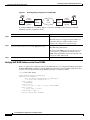
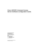
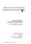
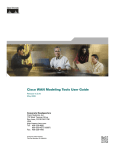
Figure 98 shows an example of a Q.SIG signalling configuration. In the example, the Cisco MC3810
either acts as a master to a slave PBX, or as a slave to a master PBX.
Cisco IOS Multiservice Applications Configuration Guide
MC-421
Configuring Support for PBX Signalling Protocols
Configuring Q.SIG PRI Signalling Support
Cisco MC3810 Q.SIG Signalling Configuration
PBX
4001
Q.SIG
E1 channel
Slave
Cisco
MC3810
No. 1
Frame Relay
DLCI 200
Master
Cisco
MC3810
No. 2
Q.SIG
E1 channel
Slave
PBX
4002
Master
14856
Figure 98
Q.SIG Prerequisite Tasks
The following configuration tasks should be completed before you configure Q.SIG on the
Cisco MC3810:
•
Configure the ports used on the Cisco MC3810 as voice ports. For information on how to configure
ports to be used as voice ports, see the “Configuring Voice Ports” section in the “Configuring Voice
over ATM” chapter.
•
Configure Voice over Frame Relay or Voice over ATM. For information on how to configure Voice
over Frame Relay, see the “Configuring Voice over Frame Relay” chapter. For information on how
to configure Voice over ATM, see the “Configuring Voice over ATM” chapter.
To configure Q.SIG PRI signalling support on the Cisco MC3810, use the following commands
beginning in global configuration mode:
Step 1
Command
Purpose
Router(config)# isdn switch-type [primary-qsig-slave
| primary-qsig-master]
Configures the ISDN switch type to serve either as
the primary Q.SIG slave or the primary Q.SIG master.
If the PINX device is the primary Q.SIG master,
configure the Cisco MC3810 to serve as the primary
Q.SIG slave. If the PINX device is the primary Q.SIG
slave, configure the Cisco MC3810 to serve as the
primary Q.SIG master.
Note
Step 2
Router(config)# interface serial 1:x
Cisco IOS Multiservice Applications Configuration Guide
MC-422
You can configure the ISDN switch type
using either this global command, or this
same command in interface configuration
mode, depending on your configuration. (See
Step 3.) If you configure the global
isdn-switch-type command for Q.SIG
support, you need not also configure the
interface isdn-switch-type command for
Q.SIG.
Enters interface configuration mode for the ISDN
PRI interface. For T1, enter serial 1:23. For E1, enter
serial 1:15.
Configuring Support for PBX Signalling Protocols
Configuring Q.SIG PRI Signalling Support
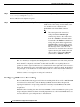
Step 3
Command
Purpose
Router(config-if)# isdn switch-type
[primary-qsig-slave | primary-qsig-master]
If you did not configure the global ISDN switch type
for Q.SIG support in Step 1, configures the interface
ISDN switch type to serve either as the primary
Q.SIG slave or the primary Q.SIG master.
The same conditions that apply to this command in
global configuration mode also apply to this
command in interface configuration mode.
Note
This interface command overrides the global
isdn switch-type command setting for this
interface.
Step 4
Router(config-if)# isdn overlap-receiving value
Activates overlap signalling to send to the destination
PBX.
Step 5
Router(config-if)# isdn network-failure-cause
[1-127]
Specifies the cause code to pass to the PBX when a
call cannot be placed or completed because of
internal network failures.
Step 6
Router(config-if)# isdn bchan-number-order
{ascending | descending}
(Optional) Configures the ISDN PRI interface to
make the outgoing call selection in ascending or
descending order.
The default is descending order, in which the first call
from the Cisco MC3810 uses channel 23 (T1) or
channel 31 (E1). The second call then uses channel 22
(T1) or channel 30 (E1), and so on in descending
order.
If you select ascending order and the PRI group starts
with 1, the first call uses channel 1, the second call
uses channel 2, and so on in ascending order. If the
PRI group starts with a different time slot, the
ascending order starts with the lowest time slot.
Step 7
Router(config)# controller {T1 | E1} 1
Enters controller configuration mode. Q.SIG is only
supported on controller 1.
Cisco IOS Multiservice Applications Configuration Guide
MC-423
Configuring Support for PBX Signalling Protocols
Configuring Q.SIG PRI Signalling Support
Step 8
Command
Purpose
Router(config-controller)# pri-group timeslot [1-31]
Configures the PRI group for either T1 or E1 to carry
voice traffic. For T1, available time slots are 1–23,
and for E1 available time slots are 1–31.
You can configure the PRI group to include all the
time slots available, or you can configure a select
group of time slots for the PRI group. For example, if
only time slots 1–10 are in the PRI group, enter the
pri-group timeslot 1-10 command. If the PRI group
includes all channels available for T1, enter the
pri-group timeslot 1-24 command. If the PRI group
includes all channels available for E1, enter the
pri-group timeslot 1-31 command.
Note
When a PRI group is configured, T1 time slot
24 or E1 time slot 16 is automatically
assigned to handle D-channel signalling.
As shown in the procedure, you have a choice of configuring the isdn-switch-type command to support
Q.SIG at either the global configuration level or at the interface configuration level. For example, if you
have a Q.SIG connection on one line and on the BRI port, you can configure the ISDN switch type in
one of the following combinations:
Note
•
Set the global isdn-switch-type command to support Q.SIG, and set the interface isdn-switch-type
command for interface bri 0 to a BRI setting such as 5ess.
•
Set the global isdn-switch-type command to support BRI 5ess, and set the interface
isdn-switch-type command for interface serial 1:23 to support Q.SIG.
•
Configure the global isdn-switch-type command to another setting (such as switch type VN3), and
then set the interface isdn-switch-type command for interface bri 0 to a BRI setting, and set the
interface isdn-switch-type command for interface serial 1:23 to support Q.SIG.
The codec command must be configured before any calls can be placed over the connection
to the PINX. The default codec type is G729a.
When voice dial peers are configured for use with Q.SIG PRI, voice port 1/1 is used for all bearer
channels.
Cisco IOS Multiservice Applications Configuration Guide
MC-424
Configuring Support for PBX Signalling Protocols
Configuring Q.SIG PRI Signalling Support
Q.SIG PRI Signalling on the Cisco MC3810 Configuration Example
The following configuration example configures interface serial 1:15 for QSIG PRI, and to act as the
QSIG master. The example shows other commands necessary for the configuration.
! version 12.1
no service pad
service timestamps debug uptime
service timestamps log uptime
no service password-encryption
!
hostname c3810a
!
network-clock base-rate 56k
ip subnet-zero
no ip domain-lookup
ip host rb 10.1.1.1
!
isdn switch-type primary-qsig-master
!
!
stun peer-name 10.1.1.1
stun protocol-group 1 basic
!
controller E1 1
clock source internal
pri-group timeslots 1-2,16
!
!
!
interface Ethernet0
ip address 144.254.156.169 255.255.255.0
no ip directed-broadcast
no ip route-cache
no ip mroute-cache
no keepalive
!
interface Serial0
ip address 10.1.1.2 255.255.255.0
no ip directed-broadcast
encapsulation frame-relay
no ip route-cache
no ip mroute-cache
no arp frame-relay
bandwidth 256
no keepalive
no fair-queue
serial restart-delay 0
frame-relay interface-dlci 30 voice-encap 80
hold-queue 1024 out
!
interface Serial1
no ip address
no ip directed-broadcast
encapsulation stun
no ip route-cache
no ip mroute-cache
stun group 1
stun route all interface Serial0 dlci 30
!
interface Serial1:15
no ip address
no ip directed-broadcast
Cisco IOS Multiservice Applications Configuration Guide
MC-425
Configuring Support for PBX Signalling Protocols
Configuring Q.SIG PRI Signalling Support
no logging event link-status
isdn switch-type primary-qsig-master
isdn bchan-number-order ascending
no cdp enable
!
interface Switch0
no ip address
no ip directed-broadcast
encapsulation frame-relay
no fair-queue
!
interface FR-ATM0
no ip address
no ip directed-broadcast
!
interface FR-ATM20
no ip address
no ip directed-broadcast
no ip route-cache
shutdown
!
router rip
network 10.0.0.0
network 144.254.0.0
!
ip classless
!
map-list atm1
!
map-class frame-relay A-relay
frame-relay traffic-rate 256000 1540000
no frame-relay adaptive-shaping
!
line con 0
transport input none
line aux 0
line 2 3
line vty 0 4
login
!
!
voice-port 1/1
!
voice-port 1/2
!
dial-peer voice 1 pots
destination-pattern 2...
port 1/1
!
dial-peer voice 3 pots
destination-pattern 3
port 1/3
!
dial-peer voice 5 pots
destination-pattern 5
port 1/5
!
dial-peer voice 6 pots
destination-pattern 6
port 1/6
!
Cisco IOS Multiservice Applications Configuration Guide
MC-426
Configuring Support for PBX Signalling Protocols
Configuring Transparent CCS on the Cisco MC3810
dial-peer voice 10 vofr
destination-pattern 4...
session target Serial0 30
!
end
Configuring Transparent CCS on the Cisco MC3810
The Cisco MC3810 provides support for transparent CCS, which provides point-to-point PINX
connection capability to Cisco MC3810 DVM interfaces when the PINX device does not support Q.SIG,
or when the PINX device has a proprietary solution.
You can configure transparent CCS in one of two ways: CCS cross-connect (or TDM cross-connect,
which implies a fractional trunk), or CCS frame-forwarding. These procedures are described in the
following sections:
•
Configuring CCS Cross-Connect
•
Configuring CCS Frame-Forwarding
Configuring CCS Cross-Connect
Configuration tasks are described in the following sections:
•
Configuring CCS Cross-Connect for T1
•
Configuring CCS Cross-Connect for E1
•
Configuring T1/E1 Trunk Bearer Channels
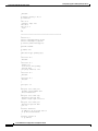
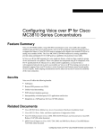
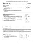
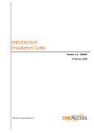
Figure 99 shows an example of CCS cross-connect. In this example, the CCS channel from the PBX is
cross-connected on the Cisco MC3810 to a time slot on the T1/E1 controller. The channel is then passed
through the WAN as a leased line to the second Cisco MC3810, where it is cross-connected to the DVM
signalling time slot (time slot 24 for T1, or time slot 16 for E1). The channel is then passed to the second
PBX. The CCS signal byte stream is passed through transparently by the Cisco MC3810.
DVM
CCS Cross-Connect Configuration
Cisco
MC3810
TDM
crossconnect
PBX
CCS
channel
T1/E1
T1/E1
Leased line
Cisco
MC3810
DVM
TDM
crossconnect
PBX
CCS
channel
14756
Figure 99
Cisco IOS Multiservice Applications Configuration Guide
MC-427
Configuring Support for PBX Signalling Protocols
Configuring Transparent CCS on the Cisco MC3810
Configuring CCS Cross-Connect for T1
When you configure CCS cross-connect for T1, you need to cross-connect from the first T1 controller
to the second T1 controller. To configure CCS cross-connect for T1, use the following commands
beginning in global configuration mode:
Command
Purpose
Step 1
Router(config)# controller T1 0
Enters controller configuration mode for controller
T1 0.
Step 2
Router(config-controller)# tdm-group tdm-group-no
timeslot timeslot-list
Configures a TDM channel group for controller T1 0.
Do not specify the type option in the command.
Step 3
Router(config-controller)# exit
Exits controller configuration mode.
Step 4
Router(config)# controller T1 1
Enters controller configuration mode for controller
T1 1.
Step 5
Router(config-controller)# mode ccs cross-connect
Configures CCS cross-connect for controller T1 1.
Step 6
Router(config-controller)# tdm-group tdm-group-no
timeslot timeslot-list
Configures a TDM channel group for controller T1 1.
Do not specify the type option in the command.
Step 7
Router(config-controller)# exit
Exits controller configuration mode.
Step 8
Router(config)# cross-connect id controller-1
tdm-group-no-1 controller-2 tdm-group-no-2
Configures cross-connect pass-through between the
two controllers.
Configuring CCS Cross-Connect for E1
When you configure CCS cross-connect for E1, you need to configure cross-connect from the first E1
controller to the second E1 controller, and then configure the mode ccs cross-connect command to allow
the cross-connect to time slot 16. This enables all of the channels to perform similarly to normal CAS
mode, but the signalling bit is no longer processed by the Cisco MC3810.
To configure CCS cross-connect for E1, use the following commands beginning in global configuration
mode:
Command
Purpose
Step 1
Router(config)# controller E1 0
Enters controller configuration mode for controller
E1 0.
Step 2
Router(config-controller)# tdm-group tdm-group-no
timeslot timeslot-list
Configures a TDM channel group for E1. Do not
specify the type option in the command.
Step 3
Router(config-controller)# exit
Exits controller configuration mode.
Step 4
Router(config)# controller E1 1
Enters controller configuration mode for controller
E1 1.
Step 5
Router(config-controller)# mode ccs cross-connect
Configures controller E1 1 to support CCS
cross-connect by enabling channel 16 to no longer
carry the signalling bit.
Cisco IOS Multiservice Applications Configuration Guide
MC-428
Configuring Support for PBX Signalling Protocols
Configuring Transparent CCS on the Cisco MC3810
Step 6
Command
Purpose
Router(config-controller-cas)# voice-group
channel-no timeslots timeslot-list type
[ext-sig-master | ext-sig-slave]
Configures the specified channel to support CCS
mode, and specifies whether the T1/E1 trunk will be
the external signalling master or slave.
A channel configured as ext-sig-master
automatically generates the off-hook signal and stays
in the off-hook state. A channel configured as
ext-sig-slave automatically generates the answer
signal when a call is terminated to that channel. These
type options are available only when the mode ccs
command is enabled.
Step 7
Router(config-controller)# exit
Exits controller configuration mode.
Step 8
Router(config)# cross-connect id controller-1
tdm-group-no-1 controller-2 tdm-group-no-2
Configures cross-connect pass-through between the
two controllers.
Configuring T1/E1 Trunk Bearer Channels
If you will use CCS cross-connect for bearer channels of the T1/E1 trunk, you will need to perform some
additional configuration. To configure the T1/E1 trunk to support CCS cross-connect for bearer
channels, use the following commands beginning in global configuration mode:
Command
Purpose
Step 1
Router(config)# controller {T1 | E1} number
Enters controller configuration mode for the
controller.
Step 2
Router(config-controller)# mode ccs cross-connect
Specifies the controller to support CCS
cross-connect.
Step 3
Router(config-controller-cas)# voice-group
channel-no timeslots timeslot-list type
[ext-sig-master | ext-sig-slave]
Configures the specified channel to support CCS
mode, and specifies whether the T1/E1 trunk will be
the external signalling master or slave.
A channel configured as ext-sig-master
automatically generates the off-hook signal and stays
in the off-hook state. A channel configured as
ext-sig-slave automatically generates the answer
signal when a call is terminated to that channel. These
type options are available only when the mode ccs
command is enabled.
Step 4
Router(config-controller)# exit
Exits controller configuration mode.
Cisco IOS Multiservice Applications Configuration Guide
MC-429
Configuring Support for PBX Signalling Protocols
Configuring Transparent CCS on the Cisco MC3810
Step 5
Command
Purpose
For Cisco MC3810 series analog voice ports:
Enters voice-port configuration mode.
router(config)# voice-port slot/port
For Cisco MC3810 series digital voice ports:
router(config)# voice-port slot:ds0-group
Step 6
Router(config-voiceport)# connection plar string
Configures the voice-port connection to support
PLAR mode. For the string, enter the number of the
voice channel that was configured as the
ext-sig-slave for the voice-group command.
Note
After a transparent CCS connection is
configured with the connection plar
command, any change to the configuration
will not take place until the connection is shut
down with a shutdown command and then
restarted with a no shutdown command. For
example, the phone number supplied in the
connection plar command can be changed
while the connection is in no shutdown state,
but the change will not cause the current
connection to be closed and a new connection
opened to the new phone number. This will
only take effect on the next no shutdown
command after a shutdown command.
The voice channel type configured as the ext-sig-master is considered the master side of the permanent
virtual circuit (PVC) connection and is responsible for establishing the PVC connection. After the
master channel is configured, a fixed timer of 30 seconds starts. The voice signalling driver then
generates an off-hook signal on the master voice channel after the timer expires. The call is treated as a
regular call, and the master voice channel will not hang up after the connection is made. If the call does
not go through, or if the T1/E1 trunk is down, the 30-second timer on the master channel side restarts.
A new off-hook signal is then generated at the master channel side after the timer expires.
CCS cross-connect is not supported on analog PVC connections.
Configuring CCS Frame-Forwarding
The Cisco MC3810 provides support for CCS frame-forwarding, which allows the Cisco MC3810 DVM
to be connected to a Private Telco Network Exchange (PTNX) without needing to interpret CCS
signalling information for call processing. CCS frame-forwarding forwards High-Level Data Link
Control (HDLC) frames over a preconfigured interface running HDLC, Frame Relay, or ATM
encapsulation.
With CCS frame-forwarding, the connection between PTNXs over the network must be point-to-point
and preconfigured. With the CCS frame-forwarding implementation, calls from the PTNX devices are
not routed, but follow a preconfigured route to the destination.
Cisco IOS Multiservice Applications Configuration Guide
MC-430
Configuring Support for PBX Signalling Protocols
Configuring Transparent CCS on the Cisco MC3810
Note
When CCS frame-forwarding is configured, the speed (clock rate) of serial interface 1 on
the Cisco MC3810 is limited to a maximum of 192 kbps. This restriction assumes that the
MFT is installed in slot 3 on the Cisco MC3810. If the MFT is not installed, then serial
interface 1 will not operate at all, but CCS frame-forwarding will be supported on other
interfaces.
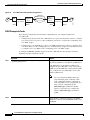
Figure 100 shows an example of CCS frame-forwarding. In the example, the Cisco MC3810 captures the
signalling frame from the PBX. The Cisco MC3810 then transports the signalling frame as a data frame
through the Frame Relay or ATM network to the second Cisco MC3810. The second Cisco MC3810 then
forwards the signalling frame to the PBX signalling channel.
DVM
CCS Frame-Forwarding
Cisco
MC3810
T1/E1
HDLC
signal
frame
T1/E1
DVM
HDLC
signal
frame
Frame Relay
or ATM
PBX
PBX
CCS
channel
CCS
channel
Note
Cisco
MC3810
14755
Figure 100
Although it is not explicitly stated in the procedures, this feature also requires that voice
ports and dial peers must also be configured.
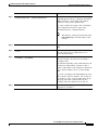
To configure CCS frame-forwarding on the Cisco MC3810, use the following commands beginning in
global configuration mode:
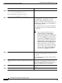
:
Command
Purpose
Step 1
Router(config)# controller {T1 | E1} 1
Enters controller configuration mode. CCS
frame-forwarding is only available on controller
T1/E1 1.
Step 2
Router(config-controller)# mode ccs frame-forwarding
Specifies the controller to support CCS transparent
signalling.
Step 3
Router(config-controller-cas)# voice-group
channel-no timeslots timeslot-list type
[ext-sig-master | ext-sig-slave]
Configures the specified channel to support CCS
mode, and specifies whether the T1/E1 trunk will be
the external signalling master or slave.
A channel configured as ext-sig-master
automatically generates the off-hook signal and stays
in the off-hook state. A channel configured as
ext-sig-slave automatically generates the answer
signal when a call is terminated to that channel. These
type options are available only when the mode ccs
command is enabled.
Cisco IOS Multiservice Applications Configuration Guide
MC-431
Configuring Support for PBX Signalling Protocols
Configuring Transparent CCS on the Cisco MC3810
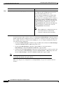
Step 4
Command
Purpose
For Cisco MC3810 series analog voice ports:
Enters voice-port configuration mode.
router(config)# voice-port slot/port
For Cisco MC3810 series digital voice ports:
router(config)# voice-port slot:ds0-group
Step 5
Router(config-voiceport)# connection plar string
If the voice port in the voice group is configured as
the ext-sig-master, configures the voice-port
connection to support PLAR mode for bearer
channels. For the string, enter the number of the voice
channel that was configured as the ext-sig-master for
the voice-group command.
If the voice port in the voice group is configured as
the ext-sig-slave, the dial peer should just terminate
the PLAR calls.
Note
Step 6
Router(config)# interface serial 1:x
After a transparent CCS connection is
configured with the connection plar
command, any change to the configuration
will not take place until the connection is shut
down with a shutdown command and then
restarted with a no shutdown command. For
example, the phone number supplied in the
connection plar command can be changed
while the connection is in no shutdown state,
but the change will not cause the current
connection to be closed and a new connection
opened to the new phone number. This will
only take effect on the next no shutdown
command after a shutdown command.
Enters interface mode for serial 1:x, where x
represents the channel number. For E1, enter 15. For
T1, enter 23.
This procedure maps the D channel from the DVM to
the specified interface.
Step 7
Router(config-if)# ccs connect {serial |atm} number
[dlci dlci| pvc vci | pvc vcd | pvc vpi/vci | pvc
string]
Configures the CCS connection. If the CCS
connection is over Frame Relay, specify a serial
interface and the DLCI. If the CCS connection is over
ATM, specify ATM, interface 0, and the PVC.
Step 8
Router(config-if)# no cdp enable
Disables Cisco Discovery Protocol (CDP) on the
interface.
Step 9
Router(config-if)# no keepalive
Disables keepalive packets on the interface.
Cisco IOS Multiservice Applications Configuration Guide
MC-432
Configuring Support for PBX Signalling Protocols
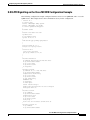
CCS Frame-Forwarding Configuration Example
CCS Frame-Forwarding Configuration Example
The following configuration example configures CCS frame-forwarding on controller E1. Other
commands necessary for the configuration are included.
! version 12.0
no service pad
service timestamps debug uptime
service timestamps log uptime
no service password-encryption
!
hostname c3810a
!
logging buffered 4096 debugging
!
network-clock base-rate 56k
ip subnet-zero
no ip domain-lookup
ip host rb 10.1.1.1
!
!
!
stun peer-name 10.1.1.1
stun protocol-group 1 basic
!
controller E1 1
framing NO-CRC4 Australia
clock source internal
mode ccs frame-forwarding
voice-group 1 timeslots 1-2 type ext-sig-master
!
!
!
interface Ethernet0
ip address 144.254.156.169 255.255.255.0
no ip directed-broadcast
no ip route-cache
no ip mroute-cache
no keepalive
!
interface Serial0
ip address 10.1.1.2 255.255.255.0
no ip directed-broadcast
encapsulation frame-relay
no ip route-cache
no ip mroute-cache
no arp frame-relay
bandwidth 256
no keepalive
no fair-queue
serial restart-delay 0
frame-relay interface-dlci 30 voice-encap 80
hold-queue 1024 out
!
interface Serial1
no ip address
no ip directed-broadcast
encapsulation stun
no ip route-cache
no ip mroute-cache
stun group 1
stun route all interface Serial0 dlci 30
!
Cisco IOS Multiservice Applications Configuration Guide
MC-433
Configuring Support for PBX Signalling Protocols
CCS Frame-Forwarding Configuration Example
interface Serial1:15
no ip address
no ip directed-broadcast
ccs connect Serial0 30
!
interface Switch0
no ip address
no ip directed-broadcast
encapsulation frame-relay
no fair-queue
!
interface FR-ATM0
no ip address
no ip directed-broadcast
!
interface FR-ATM20
no ip address
no ip directed-broadcast
no ip route-cache
shutdown
!
router rip
network 10.0.0.0
network 144.254.0.0
!
ip classless
!
!
map-list atm1
!
map-class frame-relay A-relay
frame-relay traffic-rate 256000 1540000
no frame-relay adaptive-shaping
!
!
line con 0
transport input none
line aux 0
line 2 3
line vty 0 4
password cisco
login
!
!
voice-port 1/1
vad
connection plar 1
!
voice-port 1/2
vad
connection plar 2
!
dial-peer voice 1 vofr
destination-pattern 1
session target Serial0 30
!
dial-peer voice 2 vofr
destination-pattern 2
session target Serial0 30
!
end
Cisco IOS Multiservice Applications Configuration Guide
MC-434