1
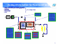
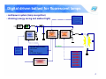
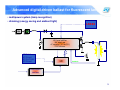
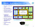
Power conversion [2/2]
Lighting
Power and analog key program
IPS & POWER CONVERSION - agenda
• Power conversion
– SMPS
•
•
•
•
Main topologies quick roundup
Power Factor Correction
PWM (offline & HV DCDC)
Low Voltage DC-DC Converters
– Lighting
• Fluorescent ballast
– Analog driven
– Digital driven / advanced
• HID
• LED / DISPLAY DRIVER
– DC / DC driven
– Offline driven
– Display control
2
Analog driven ballast for fluorescent lamps
• fully controlled pre-heating/ignition
• Relamp
• Dimming
End-of-life
• PFC
in a single chip
STTH106
STTH306
Input
Filter
Power
Factor
Corrector
STx3NK60Z
STx4NK60Z
STx6NK60Z
STx9NK60ZD
STD5NM60
STD4NK50ZD
STD5NK52ZD
STC03DE120
STC0DE150
L6561
L6562
L6563
STx3NK60Z
STx4NK60Z
STx6NK60Z
STx9NK60ZD
STD5NM60
STD4NK50ZD
STD5NK52ZD
Ballast
Controller
L6585
L6569
L6571
L6574
3
Digital driven ballast for fluorescent lamps
• multipower system (lamp recognition)
ST7DALI
ST7FLite2
ST7FLIT19B
ST7FLite0
• dimming (energy saving and ambient light)
Input
Filter
µC for
ballast
+
PFC control
Power
Factor
Corrector
L6561
L6562
L6563
OR
TD220 and TD221
LS Driver
TPR
3.3V/5V Supply
Communication
Interface
HV level
shifter
feedback
L6382
L6384
L6385
L6386
L6387
L6388
4
Advanced digital driven ballast for fluorescent lamps
• multipower system (lamp recognition)
• dimming (energy saving and ambient light)
L6382
Input
Filter
HV level shifter
HV start-up
µC supply (3.3 or 5V)
2 LS drivers
ST7DALI
ST7FLite2
ST7FLIT19B
ST7FLite0
µC
µC
feedback
Communication
Interface
5
L6585DE - Block Diagram Overview
PFC stage complete and
reliable
OVP* and feedback
disconnection protection
Anti choke saturation
protection (allows the use
of smaller PFC chokes)*
PFC OP-AMP
& OVP
End of life*, rectification
effect, capacitive mode
and hard switching
detection**
BOOT
STRAP
HALF
BRIDGE
PFC
GATE
PFC
CURRENT
SENSE
DRIVERS
LOGIC &
HALF – BRIDGE
CURRENT
SENSE
PROTECTIONS
DRIVER
Complete and
independent
programmability of
frequencies and intervals*
Vcc &
UVLO
ZCD
DETECTION
MULTIPLIER
PFC SECTION
PROGRAMMABLE
END OF LIFE
OSCILLATOR,
PREHEAT &
IGNITION
HALF – BRIDGE
Integrated bootstrap
diode
Shutdown pin*
* Updated Feature
** New Feature
6
Application example
PFC
STAGE
HB STAGE
CBULK
CBOOT
CHARGE
AC MAINS
PUMP
ZCD
INV
COMP
PFG
CT
R
L6585DE
PFCS
MULT
GND OSC
RF
Vcc BOOT
HSD
OUT
LSD
Tch EOLP EOL
EOI
LAMP
HBCS
RPRE
COSC
RRUN
CIGN
CBLOCK
TIMING AND
PROTECTIONS
7
PFC section: features
MULTIPLIER:
sinusoidal reference
superior PF performance
Wide range-Mains
operation optimized (THD
optimizer)
ZCD network
ERROR AMPLIFIER
Dynamic OVP
Compensation network
Feedback disconnection
E/A inverting input
IC shut down
Static OVP*
HB INPUT
"TM" type
IL
IAC
ZCD
AC
MAINS
CTR
MULT
PFG
CURRENT SENSE:
current mode control (1V clamp)
choke saturation protection*
leading edge blanking
COMP INV
L6585DE
PFCS
GATE DRIVER:
300mA source (typ)
600mA sink (typ)
* Updated Feature
** New Feature
8
HB Section: Normal Starting sequence
VCH =4.63V
IMAX
VREF
Tch
RD x CD
1.5V
RF
RRUN
RPRE
CIGN
1.9V
EOI
REOI
EOI
RPRE x CIGN
RD
Tch
31uA
fPRE
CD
COSC
LOGIC
OSC
(RRUN / / RPRE) x COSC
fSW
RRUN x COSC
fRUN
VLAMP
LINEAR GROWTH
VIGN
PRE-HEATING
IGNITIO
N
9
HB section: HBCS pin Features
1.
CBOOT
Ignition: Controlled lamp voltage/current
Double threshold:
•
LOW (1.6V)*: frequency increasing and Fast Tch
cycle timing (externally programmable) to limit the
current in case of broken lamp or too old lamp.
Noise immune overcurrent detection method is used.
•
HIGH (2.75)**: IC stops immediately in case of
capacitive mode caused by choke saturation.
HV BUS
BOOT
HSD
RF
LOGIC
OUT
CBLOCK
LSD
EOI
Tch
HBCS
Sense
resistor
LAMP
2. Run mode 3 levels Over-current protection:
protection
Triple threshold:
•
LOW (0.9V)*: frequency increasing and Tch cycle
timing to limit the current. Noise immune overcurrent
detection method is used.
•
MIDDLE (1.6V): IC stops immediately when a long
(300ns) hard switching pulse is detected (Capacitive
Mode protection – Lamp disconnection).
•
HIGH (2.75V)**: IC stops after 350 subsequent hard
switching pulses (40ns) in order to prevent
capacitive mode due to operation close to
resonance
Normal
Saturating
Hard
Switching
10
HB Section: End of Life protection (EOL)
HV BUS
HV BUS
CBOOT
CTR
CBOOT
BOOT
HSD
CTR
OUT
BOOT
HSD
OUT
CBLOCK
LSD
EOLP
V1
EOL HBCS
LSD
LAMP
EOLP EOL HBCS
CBLOCK
V2
LAMP
Compliant with both standard ballast configurations without circuit
change (using EOLP pin)
Precise and programmable thresholds for the EOL intervention
Filtering to delete noise effects
11
Support material
Datasheet
Demo board: STEVAL-ILB005V2
IC Application Notes: AN2870 “Combo IC for ballast control”
Developing software
simulation tool
STEVAL-ILB005V2
12
ST Lighting Designer: Overview
Start Window
Highlights
User Friendly Interface
Many IC solutions
available (Combo IC,
L6574, L6569 or
discrete)
Most Used Lamp
model available
Three main input
voltage range
selectable
Warm or Cold Ignition
design
PFC design
Dimming feature
(under development)13
IPS & POWER CONVERSION - agenda
• Power conversion
– SMPS
•
•
•
•
Main topologies quick roundup
Power Factor Correction
PWM (offline & HV DCDC)
Low Voltage DC-DC Converters
– Lighting
• Fluorescent ballast
– Analog driven
– Digital driven / advanced
• HID
• LED / DISPLAY DRIVER
– DC / DC driven
– Offline driven
– Display control
14
HID lamps
•
Metal Halide (MHD)
–
–
–
–
–
•
High pressure sodium lamps (HPS)
–
–
–
–
–
•
high efficacy,
excellent color rendition,
long service life, and
good lumen maintenance.
outdoor applications and in
commercial interiors
energy efficient.
yellow/orange light
extremely good lumens per watt.
poor colors render
exceptionally long service life (up to
40,000 hours)
Mercury Vapor Mercury
– Poor colors rendering
15
Ballast for high intensity discharge (HID) lamps
• half / full bridge configuration
• low frequency PWM (lamp resonance)
• lamp current control
L6384E
L6385E
L6386E
L6387E
L6388E
Viper16/17
L6561
L6562A
L6563
MOSFET (NM family)
IGBT (NC family)
ST7 µC FAMILY
16
Sales description
STEVAL-ILH001V1
Documentation: AN2747 on Internet
■
■
■
■
Input voltage: 90 - 265Vrms
PFC working in a fixed off-time mode
Ballast efficiency higher than 90%
Output stage: Full Bridge working in continuous
conduction mode
■ Lamp driven with low frequency (160Hz) square waveform
■ Lamp current controlled by high frequency (40kHz) buck
converter
Key Products:
STF20NM50N
STG10NB60SD
L6385E
L6562N
VIPer12AS – E
STP12NM50FP
STTH806TTI
STTH1L06
ST7FLITE39F2M3
Typical Applications:
Street Lighting
Retail Lighting
Warehouses
Industrial Lighting
Board Purpose:
To show full electronic
solution replacing
magnetic ballast with
better efficiency and
feature set
17
STEVAL-ILH003V1
Lighting
Coming
Coming soon
soon
70W HID Lamp Ballast based on L6569A and L6562A
Features:
■ 50/60 Hz 88V ~ 264V wide input voltage range
■ Easily drive of a 70W metal halide lamp
■ PFC working in Fixed-On-Time.
■ Two-stage topology
■ Warming up state for start-up
■ Illuminate in steady state
■ Dual Buck-Converter solution
■ Lamp driven with low frequency (200Hz)
HB buck converter
■ Lamp current controlled by high
frequency HB buck converter
■ Load power control technique
■ Ballast efficiency higher than 88%
Driver: L6385ED
18
IPS & POWER CONVERSION - agenda
• Power conversion
– SMPS
•
•
•
•
Main topologies quick roundup
Power Factor Correction
PWM (offline & HV DCDC)
Low Voltage DC-DC Converters
– Lighting
• Fluorescent ballast
– Analog driven
– Digital driven / advanced
• HID
• LED / DISPLAY DRIVER
– DC / DC driven
– Offline driven
– Display control
19
How to control LED Light output
Current vs. wavelength characteristic
(Power TOPLED Datasheet - OSRAM)
20
LED Lighting and Norms
PFC: even when LEDs are used,
EN 61000-3-2 is valid for LED-Lighting too!
=> At output power ≥ 25W only with active PFC
(Power Factor Correction) is this norm achievable
21
Solution for Color LED displays based on
STP24DP05 and STM32
Advanced display LED array
drivers, control and reference
designs
Application examples
Signs
Full-color
Monochrome
Signals
Traffic
Other
Automotive
Automobile exterior (stop/tail/turn lights)
Automobile interior (instrumental panel and dashboard)
Truck and bus exterior
Display backlighting
PDAs, MP3 players and digital camera backlight
Mobile phones displays
Keyboard backlight
Other displays
Specialty illumination
Flashlights, headlights
Architectural and design lighting
Emergency lighting
Water features and pools
Home Appliance
System Indicator lights
Advertising
Information panels
Special light effects in shop windows
Industrial application
23
Applications for LED Display Drivers
Color LED displays, panels and signs
- Colored
traffic signs
- RGB lighting for gaming and gambling machines
- RGB LED matrix displays
- LED advertisement billboards
- Graphic boards
- Variable message signs
24
LED Array
Big panel, LED display, Traffic signs,…
STP04CM05
STP08CP05
STP08DP05
STP16CP05
STP16DP05
STP16CPS05
STP24DP05
Viper Family
Current Mode CPWM Controller
Microcontroller
ST7, STM8S
STM32
25
LED array sink drivers
Features:
•
•
•
•
•
•
•
•
•
•
•
•
•
LED array sink drivers block diagramm
Low voltage power supply 3.0 to 5.5V
Voltage capability at Outputs: 20V
4, 8, 16, 24 constant current output channels
Adjustable output current through external resistor
Serial data in / parallel data out
Serial out changes state on the raising edges of
clock
Up to 30MHz clock frequency
3.3V micro driver-able
Output current 3 – 500mA
(depending on type of STPxxyy05)
Thermal protection
Auto Power save at STPxxCPS05
LED failure detection at STPxxDP05
Available in high thermal efficiency TSSOP
exposed PAD
26
ST : a Complete Solution Portfolio
Vin
[VDC]
Iout
[mA]
Vout
[VDC]
No of
channel
Remark
Ref Design
STP04CM05
3.3 to 5.5
50 to 500
16
4
SPI; dimmable current
sinkPWM dimming, thermal
protection
STEVAL-ILL009V1
STEVAL-ILL009V3
STEVAL-ILL009V4
STP08CP05
4.5 to 5.5
5 to 100
20
8
(STEVAL-ILL003V1)
(STEVAL-ILL003V2)
AN2141
STP08DP05
3.3 to 5.5
5 to 100
20
8
STEVAL-ILL002V(1)/3
AN2415
STP16CP05
4.5 to 5.5
5 to 100
20
16
SPI; dimmable current sink,
thermal protection
error detection; SPI;
dimmable current sink, therm
Andreas Sawka
prot
SPI; dimmable current sink,
thermal protection
STP16CPS05
4.5 to 5.5
5 to 100
20
16
STP16DP05
3.0 to 5.5
5 to 100
20
16
STP24DP05
3.0 to 5.5
5 to 100
20
16
STPIC6A259
4.5 to 5.5
350
33
8
error detection; SPI;
dimmable current sink, therm
prot
error detection; SPI;
3 currnet source values,
dimmable current sink, therm
prot
SPI; Automotive
STPIC6C595
4.5 to 5.5
250
33
8
SPI; Automotive
M5450x / M548x
4.75 to 13
25
13
34 / 35
Adjustable current sink
Part
SPI; dimmable current sink,
thermal protection
Auto Power Save
App
Note
AN2531
STEVAL – ILL002V(2)4
STEVAL-ILL003V(1)/2
AN2141
STEVAL-ILL003V(1)/2
AN2141
AN2141
STEVAL-ILL015V1
AN2141
27
STP24DP05
Limitation on current solutions for full-color Display
5v
3.3v
Complicated PCB routing
OE
SDI
LE
CLK
STP08DP05
08 Shift Register Constant
Current Drivers
Green
SDO
OE
SDI
LE
Rext
CLK
STP08DP05
08 Shift Register Constant
Current Drivers
Blue
SDO
OE
SDI
LE
Rext
CLK
STP08DP05
08 Shift Register Constant
Current Drivers
SDO
Rext
Red
28
STP24DP05
Advantages of 24-channel solution
5v
3.3v
STP24DP05
RextB
RextG
24-bit Shift Register
Constant Current Drivers
RextR
RGB grouping
TSD
SDO
EF
OE-R / DM
OE-G
OE-B
G4
B4
G4
R3
B3
G3
R2
B2
G2
R1
B1
G1
CLK
SDI
LE/ / DM
DM
TF
DG
DF0
DF1
Thermal Shut-Down
G5
B5
R5
G6
B6
R6
G7
B7
R7
G8
B8
R8
Individual current
setting for each color
channel
29
STP24DP05 Basic Features
Key Features
■ Accept 3.3v and 5v micro driver
■ 8 x 3 Channel groups of constant
current output channels
■ Adjustable output current through
one external resistor for each group
of 8-channel
■ Short and Open Output Error
Detection via SPI and flag pin
■ Serial Data IN / Parallel Data OUT
■ SPI Serial Interface
■ Gradual Output Delay
■ Thermal Shutdown with flag pin
■ Excellent Current Accuracy
■ Output Current: 5-80mA
■ 25MHz Clock Frequency
STP24DP05
STP24DP05
SDO SDI
STP24DP05
SDO
SDI
REXTs
REXTs
SDI
SDO
REXTs
30
Purpose of Reference Designs of LED Array
• Aimed to customers working on applications with high
number of low power LEDs
– either color or monochromatic
• Open software architecture - easily integrates Demo
– USB and JTAG programming connectivity to use the board as a
simple development tool
• Gerber Files, PC Software,... : available
• Here as example : STEVAL-ILL015V1
– 6-rows 30mA LEDs driver with buck regulator
– Applications: Indoor or outdoor use, LED advertisement billboards,
Graphic boards, Colored traffic signs, Variable message signs…
– Key Products: STP24DP05, STM32F103, ST1S10
– Documentation: AN2841, UM0574 & UM588 published
31
STEVAL-ILL015V1 Block description
USB
Reference
design
SPI
ESD for USB
USBUF01P6
LED driver
STP24DP05
SPI
Power supply
ST1S10
LED driver
STP24DP05
STM32
SPI
4.5V
STM32
3.3V
USB
LEDs
LED Drivers
Open jumpers
POWER
Short jumpers
7-18V
JTAG
RGB LEDs
Error Flag
RESET
Buttons
Knob
Temperature flag
32
STEVAL-ILL015V1
Functionality #1 - PC Interface
Reference
design
Firmware modes:
• 8-bit resolution mode for each color
16 million colors demonstration
• Animated text menu:
Simple game, Wave color demo, Solid color demo, LED diagnostic
Software features:
• USB interconnection, Virtual comport driver used
• LED diagnostic during any running firmware demo
• Demoboard firmware mode control by on-screen buttons instead of on-board buttons
USB
33
STEVAL-ILL015V1
Functionality #2 - LED dimming using shift registers
Application
Know-how
STP24DP05
STP24DP05
SDO SDI
STP24DP05
SDO
SDI
REXTs
REXTs
SDI
SDO
REXTs
Cascading Principle
Shift Register LED Driving Principle
34
STEVAL-ILL015V1
Functionality #2 - LED dimming using shift registers
Example for 4-channels – 8bit resolution dimming
T SW_PWM
DATA
1111
1101 0101 0001
0000 1111 or new data
256 LEVELS
t
Output 1
4% Duty Cycle
Output 2
t
14% Duty Cycle
Output 3
t
3% Duty Cycle
Output 4
t
99% Duty Cycle
t
35
STEVAL-ILL015V1
Functionality #2 - LED dimming using shift registers
Look-up table
PWM waveforms for each LED stored in RAM
RAM
LED Driver
SPI
…..
…..
36
STEVAL-ILL015V1
Functionality #2 – LED Dimming - C library
Make the designer’s life easier!
UM0588 – dimming C library user manual
Library key features:
• source files for STM32 and STM8
• peripheral pre-setting (timer, DMA, SPI) to requested values
• timer running on background (interrupt (STM8) or interrupt + DMA (STM32))
• simple addition of customer foreground and background tasks
• brightness and color of each LED defined by three (R, G, B) variables
37
STEVAL-ILL015V1
Functionality # 3: Output Error Detection
Case One:
Open Line
Case Two:
LED Shorting
Case Three:
Short To GND or Vo
Vo=LEDs
voltage supply
5v
3.3v
STP24DP05
STP24DP05
STP24DP05
Normal Mode Serial Data
SDO
OR
SDI
SDO
SDI
REXTs
REXTs
SDI
Normal Mode Serial Data
SDO
REXTs
OR
Error Detection
Serial Data Result
Entering in Error
Detection Mode Serial
Data
38
Tools and Documents
• Reference Design STEVAL-ILL015V1
• Application Note: AN2841
• User Manuals:
– UM0574 HW
– UM0588 C Firmware library
• Datasheets
– STP24DP05
– STM32F103
– ST1S10
39
STP16CPS05: Autoshutdown functionality:
A hypothetical case…
IDD (ON) = 11.7mA (typ)
IDD (Shut-down) = 100uA (typ)
ICC(SHUT-DOWN)
is 117 times less
than ICC(ON)
Power Savings – An example
• LED panel size
• Estimated number of LED Drivers
• LED drivers active at any one time
: 10m x 5m
: 10,000 pcs
: ~ 20%
Х Using std LED driver All 10,000 will consume
high current (approx 117 A)
√ Using STP16CPS05 Only 2,000 will consumer
high current (approx 23 A)
Power savings using STP16CPS05 is ~ 80 %
40
LED array sink drivers Applications
32 LED array evalution board (without diagnostic)
based on advanced logic STP16CP05 and STP16CPS05
Documentation:
AN2141
Features:
• 32 LED Matrix is driven
• Adjustable Brightness
• Led current regulation
• Adjustable blinking speed
• Different blinking modes
• Animated text
• Input voltage from 5V to 35V
• DC/DC Pre-regulator for high efficiency
Key Products:
STP16CP05
STP16CPS05
ST7FLITE09
L5970D
L78L33
Typical Applications:
LED Information Panels
LED Displays
Traffic Signs
Signals
Decorative Lighting
Home Appliances (White
Goods)
STEVAL-ILL003V2
41
40 LED array evaluation board (with diagnostic)
based on advanced logic STP08DP05
Documentation: AN2141, AN2415, AN2478
OSRAM LEDs
Features:
• 40 OSRAM BLUE LED Matrix is driven
• Open and Short Line error detection
• Adjustable Brightness
• Led current regulation
• Adjustable blinking speed
• Different blinking modes
• Animated text
• DC/DC Pre-regulator for high efficiency
Key Products:
ST7FLITE
STP08DP05
ST232
L5970D
STEVAL-ILL002V3
Typical Applications:
LED Information Panels
LED Displays
Traffic Signs
Signals
Decorative Lighting
Home Appliances (White
Goods)
42
40 LED array evaluation board (with diagnostic)
based on advanced logic STP08DP05
Documentation: AN2141, AN2415, AN2478
Vishay LEDs
Features:
• 40 TOSHIBA GREEN LED Matrix is driven
• Open and Short Line error detection
• Adjustable Brightness
• Led current regulation
• Adjustable blinking speed
• Different blinking modes
• Animated text
• DC/DC Pre-regulator for high efficiency
Key Products:
ST7FLITE
STP08DP05
ST232
L5970D
Typical Applications:
LED Information Panels
LED Displays
Traffic Signs
Signals
Decorative Lighting
Home Appliances (White
Goods)
STEVAL-ILL002V4
43
AC/DC single package drivers
VIPer+ with minimum stand-by
consumption
Offline LED Driver
Illumination, Architectural Lighting, General Lighting
Peak Clamp
PKC-136
Ultra fast 200V, 300V, 400V diodes
N-Channel MOSFET
Current Mode PWM Controller
Quasi-Resonant Controller
Viper Family
Viper12/22A
Viper17 (+)
Viper27 (+)
Viper53
TSM family
TSM101
TSM102
TSM103
TSM104
Application
notes
AN1916
AN2042
AN2067
AN2011
AN1059
AN1060
45
Offline LED Driver
• Illumination
• Architectural & design lighting
INPUT
Vin [VAC]
OUTPUT
Iout
[mA]
Vout
[VDC]
• Emergency lighting
• Water features and pools
Main
ST-Parts
Remark
90 to 264
350
3.0 to
15
90 to 264
350
6.0 to
27
VIPer22 &
TSM103
85 to 135
or 185 to
265
350
3.5 to
28
VIPer22 &
TSM104
176 to 264
500
3.5 7(max)
*
Viper17 &
TSM103W
82 to 265
200 to
1000
5 to 40
VIPer53 &
TSM101
90 to 265
Up to
700
Up to
48
L6562A &
TSM1052
Insulated output
constant current
source
Insulated output
constant current
source
Insulated output
Dimmable current
source
non-insulated
Constant current
source
Insulated output
Dimmable current
source
Insulated PFC &
current source
88 to 265
350 or
700 or
1000__
Up to
400VD
C
L6562A & HV-Pwr
MOSFETs &
rectifier
80W LED Driver
Non–insulated SMPS:
PFC & Modified Buck
VIPer12A &
TSM103
Andreas Sawka
Ref Design
App Note
STEVALILL005V1
AN1916
STEVALILL006V1
AN1916
STEVALILL001V1
AN2042
STEVALILL017V1
AN2811
Schematic
and layout
AN2067
EVL6562A35WFLB
AN2838
STEVALILL013V1
UM0670
(Coming soon)
* Limited Vout in STEVAL-ILL017V1, VIPer17 can provide also up to 15V and 350mA
46
Low Power Offline LED Driver Topologies
• Buck converter
– Q1 at high side requires a floating gate-drive
– Inherent L-C filter provides low ripple current
– Very short duty cycle with big Vin to Vout ratio
• Modified or inverted buck
converter
– Q1 at low side, the gate-drive is referred to
ground
– Vout is referred to high side
– Inherent L-C filter provides low ripple current
– Very short duty cycle with big Vin to Vout ratio
• Flyback converter
– Flyback transformer is required. It also
provides bias for Q1 & Vaux for PWM controller
– Low input current and optimized duty cycle also
with big Vin to Vout ratio
47
VIPer22A Application Example
Application described in AN1916
- Isolated flyback configuration
- Constant current output (350mA)
- Output voltage from 5,7V to 27V
- 8 LEDs can be driven with 350mA
output current (Vf = 3.4V)
Evaluation Board: STEVAL-ILL006V1
Dimmable Evaluation Board: STEVAL-ILL001V1
48
STEVAL-ILL017V1 – Reference Design
• 2W not-insulated Offline Constant Current LED
driver
– The PCB dimension is important
– No line isolation is required
• The specification is as following
Parameter
Value
AC input
220 VAC +/- 20%
Output current
500 mA
Output voltage
7 VDC maximum
Dimension
30 mm x 30 mm
Isolation from mains
Not required
Topology
Constant current source
49
STEVAL-ILL017V1 : Miniature size
50
STEVAL-ILL017V1 :
Offline Constant Current Control
•
•
•
•
•
Not isolated (common ground)
R9 &R12, the output-current sensing resistor
R7 & C7 compensation circuit of U2 in order to drive Q1 properly
Bridge R10 & R11 to provide 0.3V reference from Vref in pin 3 of U2
Q1 the buffer stage to feed signal to U1
51
STEVAL-ILL017V1 :
Load efficiency and stdby power
52
ST Products and technical document
• VIPER17HN
– Offline high voltage converter (115 KHz)
• TSM103W
– Dual operational amplifier and voltage reference
• STPS2H100A
– Power Schottky rectifier
• STTH1R06A
– Turbo 2 ultrafast high voltage rectifier
• BAT46JFILM
– Small signal Schottky diode
• AN2811
– Application note of STEVAL-ILL017V1
53
More application fields
• Applicable fields
–
–
–
–
Fridge / Refrigerator
Night light for indoor use
Guiding indicator
…
54
Insulated Flyback solution with High PF (1)
T1
1
180Vac-265Vac
2 -
D0
FUSE
R1
330k
L1
+ 4
C4
1.5nF 250V
C1
C2
(100nF X2)
(10nF)
D4
BRIDGE
R2
100
3
AC IN
6
Vout
12
OPTO
D1
D3
R4
10
R6
1
C20
(2k)
VDD
DRAIN
GND
DRAIN
22
RH
D5
4
3
C9
(1uF)
Dout1
3.5V 350mA
VIPer17
CONT
330nF
Cout
Vcc
BR
C6
RL
100uF
R13
0
TSM1052
C
D3
Ictrl
OUT
R7
C5
C60
(10uF)
Dout2
3.5V 350mA
22k
22k
R8
2.2nF
C10
E
OPTO
R10
(2.7k)
R11
377mA (typ.)
4.7k
10nF
C50
(2.2nF Y1)
-R11=0.53Ω
-RH=1.43MΩ
-RL = 3.3KΩ
-Cout=570µF
-Cin = 10nF
R12
1.8k
Vs
(100uF)
R9
GND
FB
220nF
Vctrl
C7
C3
.
Concept is based on the capability of modulating the Input
Current according the mains voltage; it is done thanks to the
Viper Current limit internal circuit and to the external resistor
divider composed by RH and RL connected between the input,
CONT pin and ground.
Input capacitor, C2, is ceramic and only 10 nF.
55
Insulated Flyback solution with High PF (2)
The three figures show input and output voltage and current obtained from
the schematic described in the previous page used to supply 3x1 W series Led.
Vin = 180 Vac
PF = 0.944
Vin = 230 Vac
PF = 0.917
Vin = 265 Vac
PF = 0.882
56
AC/DC high efficient solutions
for general lighting and street
lighting
Offline LED Driver (Non-/Isolated)
Illumination, Architectural Lighting, General Lighting
Peak Clamp
PKC-136
Ultra fast 200V, 300V, 400V diodes
N-Channel MOSFET
Current Mode PWM Controller
Quasi-Resonant, TM PFC Controller
Viper Family
Resonant Controller
TSM family
TSM101
TSM102
TSM103
TSM104
Application
notes
AN2838
UM0670
Viper12A
Viper22A
Viper53
Viper17
58
L6565
Quasi Resonant Controller
•
•
•
•
•
•
•
•
•
•
•
Current mode quasi resonant PWM controller
Micropower start-up current (< 75 uA)
Low quiescent current (3 mA typ.)
ZCD input for QR operation
Frequency foldback function
Line voltage feedforward function
Pulse-by-pulse overcurrent protection
2nd overcurrent level with latched shutdown
Disable function
Internal current sense RC filter
Package: SO-8 / Minidip8
For LED application it is used as a standard fly-back converter with current
regulator on the secondary side (e.g. with TSM10xW )
59
L6562AT PFC Controller
• Guaranteed for extreme temp range
(outdoor – Streetlighting)
• Transition-Mode controller of PFC
• Proprietary Multiplier for min THD
• Micropower start-up current (< 30
uA)
• Low quiescent current (2.5 mA typ.)
• ZCD inputfor TM operation
• Very precise adjustable output OVP
• 1% internal reference
• On Chip Filter on current sense
• Pulse-by-pulse overcurrent
protection
• Disable function
• Internal current sense RC filter
• Package: SO-8 / Minidip8
For LED application it is used as a standard fly-back converter
with
current regulator on the secondary side (e.g. with TSM10xW )
60
L656x Application
Modified Non-Isolated Buck Controller for LED Supply
VI
Modified buck (step-down)
N
• Suitable for applications
- not isolated
- not requiring PF
e.g. emercency light,
trafficlight...
• MOS referred to ground
and not to VIN
(low voltage driver)
• Open loop operation
(frequency accuracy required)
• Working range:
nVLED < VIN(MIN)
• D = nVLED / VIN
nVLE
D
D
L
DIODE
• VRRM > VIN
• IAVG = I LED x (1 –
D)
MOS
• VDss > VIN
• IRMS2 = I LED2 x
D
M
INDUCTANCE
• charges on VIN –
nVLED
• discharges on nVLED
I LED
M
D
M
61
L656x Application
Modified Non-Isolated Buck Controller for LED Supply
• Flexible Number of LEDs IN
SERIES (eg. 30 x 1W GOLDEN
Vac
BRIDGE
56µF
DRAGON)
330pF
1N4148
47
• E.g. Vin = 110Vac or 230V
2.1mH
1N4148
• Measured efficiency ~ 90% (but
Vcc
application fine tuning is still
necessary, e.g. MOS, DIODE)
4.7µF
GND
GD
L656x
CS
INV
COMP VFF ZCD
4.7
1N4148
1.5K
2.7K
GREEN: LED CURRENT
BLUE: SENSE RESISTOR VOLTAGE
220pF
560pF
FIXED OFF
TIME
NETWORK
PWM dimming
62
Non-Insulated Offline LED Driver for
Fashionable Lighting (1/2)
Input:
- Active PFC
- Wide input voltage range (88 – 264VAC)
Output:
- Current source 350, 700mA, 1000mA
adjustable mean value
- Output power 80W
- Max current ripple ±100mA
- Dimmable 0 – 100%
Dimension
- 60 x 130 x 27 mm
Efficiency (prototype)
- ~90%
63
Non-Insulated Offline LED Driver for
Fashionable Lighting (2/2)
16V_primary
R102
750k
R105
180k
C109 12nF
T101
V+_DC_High
D102
STTH1L06
R106
R113
750k
1
R104
180k
6
10
R101
750k
5
C104
220nF/X2
100R
CMC 20mH/1A
C105
470n
1
U101
L6562
8
VCC
DF500
R103
10k
MULT
GND
3
C106 C107
100n
22uF/25V
PFC for >25W Input
C110 1u
2
D104
18V/0.5W
4
R114
750k
R107
68k
COMP
3
TRNSFMR 67128990
D103
1N4148
5
+
CON3
D101
ZCD
C103
C102 220nF/X2
1n/Y1
6
3
2
1
L101
NTC 10R
2
J2
L102 330uH/1A
RT101
R108
12k
C111
470n
INV
GD
C113
47u/450V
1
R109
V+_DC_High
7
33R
CS
C101
1n/Y1
C108
10n
1
2
R115
10k
R110
C112
100p
1k
R111
0R41
J3
Q101
STP8NM50
4
F101 2A/T
E25x13x7
1.5mm gap, N67
Primary: 105 turns 2x0.3
Secondary: 11 turns 1x0.3
LEDs
R116
200k
R201
100R
R112
0R41
CON2
V-_DC_High
STEVAL-ILL013V1
Demoboard on stock May
D105
STPS5L60
16V_primary
C203
1n/500V
C201
100nF
U3
1
2
3
4
C202
22uF/25V
L6565
L201
INV
Vcc
COMP
GD
VFF
GND
CS
ZCD
8
R202
Q3
STP8NM50
7
C204 220pF
6
33R
D106
STTH1L600
ETD29
1mm gap, N67
208 turns 2x0.4
D108
STTH1L600
5
R2032k7
C205
1n
D107
1N4148
R204
9k1
V-_DC_High
R206 R207 R208
5R6 5R6 5R6
R2051k
Offline LED Driver
64
L6562A Insulated High PF AC/DC LEDs Driver 35W
EVL6562A-35WFLB
AN2838
New
65
L6562A Insulated High PF AC/DC LEDs Driver 35W
66
L6562A Insulated High PF AC/DC LEDs Driver 35W
• L6562A in fly-back topology addresses medium
power LED applications offering :
– Cheap and flexible Insulated Single Stage
conversion
– PF greater than 0.9
– NO electrolytic input capacitor
– NO electrolytic output capacitor if its value allows
the use of ceramics
• Key Components:
– L6562A(T), TSM1052, STP5NK80ZFP, STTH1L06,
STTH3R02
• Tools:
– EVL6562A-35WFLB (voltage output can be expanded
to Curr Ctrl)
67
– AN2838
Topologies & Solutions for Street Lighting
New trend for High power Street lights is based on LEDs due to
:
reliable and safe
technically advanced
economical
environmentally friendly
convenient for maintenance
save energy
improve light quality
68
Comparison Lighting Quality with LED and HPS lamps
Source:
Source: Osram Opto Semiconductor
69
Comparison Lighting Quality with LED and HPS lamps
70
LEDs Street Light
Current solutions in the market are facing some main bottlenecks:
– Life time of the solution: after 1.5 years a lot of failures in LED
and power supplies. One of the most critical components in the
power supply is the E-CAP.
– Wide range of temperature operation: still a lot of problems in
sustaining adverse weather operating conditions and power
dissipation
– Market maturity: This business has a very high potential but it is
still in the demand creation phase and waiting for the adoption
form local governments.
71
LED Street Light : ST solution
ST addresses all these bottlenecks with a solution based on
PFC+LLC
ac mains
85–305 Vac
PFC
L6562AT
LLC
L6599AT
90W – 250W
AC DC
48 V/130W
R LED
R LED
Inverse
Buck CC
regulator
Inverse
Buck CC
regulator
DIMMING
DIMMING
Demo board in development
L6562AT and L6599AT are guaranteed over -40 to +125 degrees
making them suitable for reliable power supply with very
aggressive
form factor easily fitting all the current street lamp solutions.
72
Schematic of Streetlighting PFC + Resonant Circuit
Suitable for 120W Streetlighting,
Streetlighting, sizeable to 250W
73
Streetlighting PFC + Resonant Circuit
• Key components:
–
–
–
–
–
PFC L6562AT
Resonant Controller L6599AT
MOSFETs: STP21NM50N, STP8NM60N
Ultrafast Diode: STTH3L06U
Schottky Diodes: STPS1015DCG
• Tools:
– Reference board in design
– AN in preparation
74
Switching DC/DC up to 2.8A
supply and control for general
lighting and automotive
Low Voltage LED-Driver
Where Vin < V(LED) use Step Up topology*.
Where Vin > V(LED) use Step Down
topology*.
Inputhigh PWM
Output
For
dimming frequency or small system size use Linear Current Source.
Vin
[VDC]
Vout
[VDC]
Iout
[mA]
ST-Part
Remark
Ref Design
App Note
Step Up
2.5 to 5.0
3.5 to 5.0
Up to 18.5
Up to 37.0
20
40
STLD20D
STLD40D
Step up current control
STEVAL-TLL001V1
AN2333
0.6 to 5.5
2 to 5.2
500
L6920
Step up current control
STEVAL-ILL008V1
AN1891, AN1941
4.5 to 36
Up to 36
6 X 30
6 X 85
LED7706
LED7707
1 x Step up ; 6 x linear
current sink, dimmable
EVALED7706
EVALED7707
AN2806
Step Down
8.0 to 18
2.5 to 14
10002800
L6726+
STS8DNH3LL
Step down current control
dimmable
STEVAL-ILL023V1
In preparation
8.0 to 36
1.235 to
34
1000
L6902
Step down current control
dimmable
STEVAL-ILL010V1
AN1891, AN1941, AN2129
4.4 to 36
1.2 to 35
2500
L5973
Step down current control
STEVAL-ILL007V1
AN2259
8.0 to 55
3.3 to 50
1000
L4976
Step down current control
e.g. 700
L6562 +
PowerMOS
Modified Buck. Vin; Vout;
Iout depend on PowerMOS
mainly
e.g. 100
<Vin
AN1891
Schematics
available
Linear current source
4.5 to 40
4.5 to 40
500
1500
2000
STCS05
STCS1
STCS2
* for buck/boost ref. AN1891 and AN1518
Linear constant current
source.
PWM dimming up to 50kHz
STEVAL-ILL014V1
UM0422
76
Step-down topology
Signage, Torch, portable lighting
Power Schottky Diode
Application
notes
L6902
L597X
L497X
ST1S10
AN1891
AN1941
AN 2129
L6925
L6926
77
L6902D and Automotive A6902
Up to 1A switching regulator, with adjustable current limit
•
•
•
•
•
•
•
•
•
•
Step-down switching regulator
Up to 1A output current
5% output current accuracy
Adjustable current limit
Thermal shutdown
250KHz internally fixed frequency
Precise 3.3V (±2%) reference voltage
Operating input voltage from 8V to 36V
Output voltage adjustable from 1.235V to 34V
Protection against feedback disconnection
78
STEVAL-ILL010V1 - L6902D Reference Design
• Designed for 350mA LEDs
U1
8 - 24V
• Fully dimmable board
4
+
C1
10uF
25V
CERAMIC
C3
22nF
C4
220pF
J2
L6902D
VCC
OUT
COMP
CS+
CS-
VREF
8
GND
2
1
100uH
FB
1
R1
9k1
D1
STPS34OU
+
C2
10uF
35V
1
2
Output
2
3
R4 1k
5
6
J1
7
• Easily modification for higher
current
L1
R2
5k1
R3
R6
27k
510
R5
8k2
Rsense
0.33
• Analog dimming
• Digital (PWM) dimming
1
1
• 5 LEDs can be driven with 700mA
output current (Vf = 4.4V)
1
• Maximum output voltage limited
J3
3.3V Vref
J4
J6
GND
Dimming Input
• 6 LEDs can be driven with 350mA
output current (Vf = 4V)
• Reference Documentation : AN 2129
More LED applications in AN 1891, AN 1941
79
L597x Family
Step down switching regulator
L5970D
1A switch in SO8
L5970AD
1A Switch in SO8
500kHz switching frequency
L5972D
2A switch in SO8 (4 ground leads)
L5973D
2.5A switch in HSO8
4.4V to 36V input voltage
Internal P-channel DMOS transistor (with a typical Rds
on of 250mΩ).
L5973AD
2A switch in HSO8
500kHz switching frequency
adjustable output from 1.25V
250kHz or 500kHz internally fixed frequency
3.3V reference available (L5972D)
Inhibit for zero current consumption (except L5972D)
Internal current limiting
Protection against feedback disconnection
Thermal shutdown and Synchronization
80
L597x Application Schematic
Circuit for driving up to 6 LEDs
Application described in AN 1891
81
Application Example L597x:
MR-16: Halogen socket LED replacement Solution
•
•
•
•
•
•
•
•
LED bulb based on halogen MR16.
Solution has very small footprint.
ST’s solution uses the L5970.
This board is intended to work with a 12VAC input (works
4.4V < Vin < 36V).
This board is shown driving a single 3W white LED.
The board can also drive a 1W or future higher wattage LED
with some resistor changes.
Order Code: STEVAL-ILL007V1
Application Note AN2259
1.25”
82
Application Example L5973AD:
1000 lumen OSTAR LED Driver
Main Characterisitics:
• Input voltage Vin: 5 - 30V DC
(limited by transil)
• Switching Frequency 500KHz
• Output current: Iout = 1A,
optionally 350mA or 700mA by
jumper setting
• Output voltage Vout < Vin
• Short circuit, over temperature
protection
• Drives 1000 lumen OSTAR with
1A at Vin>24V
Demoboard
83
L597x Family
HSOP8
More than 2A in small SO8 package
with minimum external component
count
P-channel power MOS: no bootstrap
capacitor
Wide input voltage range (4.4V up to
36V)
High switching frequency
(250KHz/500KHz, sync up to 700KHz*)
Inhibit pin*
Suggested
Embedded protection features
when
Typ RDSon=250mΩ
Vin>18V
Device
L5970D
L5970AD
L5972D
L5973AD
L5973D
Package
SO8
SO8
SO8
HSOP8
HSOP8
Ipk [A]
1.5
1.5
2
2
2.5
Iout [A]
1
1
1.5
1.5
2
Vin (V)
4.4V to 36V
4.4V to 36V
4.4V to 36V
4.4V to 36V
4.4V to 36V
SO8
L5973D
L5973D
L5973AD
L5973AD
1.5A / 500KHz
L5972D
L5972D
1.5A / 250KHz
L5970AD
L5970AD
1A / 500KHz
L5970D
L5970D
1A / 250 KHz
Vout (V)
0.5V to Vin
0.5V to Vin
1.23V to Vin
0.5V to Vin
0.5V to Vin
2A /250KHz
Fsw [KHz]
250
500
250
500
250
Extra functions
Inhibit, Vref, Sync
Inhibit, Vref, Sync
Inhibit, Vref, Sync
Inhibit, Vref, Sync
* all but L5972D
HSO8 - Rth jj-amb 40C/W
SO8 - Rth jj-amb 115C/W
Rth jj-amb 62C/W for L5972D
84
DC-DC converters – A597xD for Automotive
More than 2A in small SO8 package with
minimum external component count
P-channel PowerMOS: no bootstrap
capacitor
Wide input voltage range: 4V up to 36V
High switching frequency: 250kHz
/500kHz
Inhibit pin
Embedded protection features
Operates over the -40°C to +125°C
temperature range
BURN-IN test for high reliability (B5973D)
HSOP8
SO8
B5973D
2A / 250kHz
A5973D
2A / 250kHz
A5973AD
1.5A / 500kHz
A5972D
1.5A / 250kHz
A5970AD
1A / 500kHz
A5970D
1A / 250kHz
Device
Package
Ipk (A)
Iout (A)
Vin (V)
Vout (V)
Fsw (kHz)
Toperating
Extra functions
A5970D
SO8
1.5
1
4V to 36V
0.5V to Vin
250
-40°C to +125°C
Inhibit, Vref, Sync
A5970AD
SO8
1.5
1
4V to 36V
0.5V to Vin
500
-40°C to +125°C
Inhibit, Vref, Sync
A5972D
SO8
2
1.5
4V to 36V
1.23V to Vin
250
-40°C to +125°C
-
A5972AD
HSOP8
2
1.5
4V to 36V
0.5V to Vin
500
-40°C to +125°C
Inhibit, Vref, Sync
A5973D
HSOP8
2.5
2
4V to 36V
0.5V to Vin
250
-40°C to +125°C
Inhibit, Vref, Sync
B5973D
HSOP8
2.5
2
4V to 36V
0.5V to Vin
250
-40°C to +125°C
Inhibit, Vref, Sync
85
L598X Family
More than 2A in small QFN3x3-8L package
L5989D
L5989D
up to 4A /
HTSSOP16
with minimum external component count
L5988D
L5988D up to 1MHz
P-channel power MOS: no bootstrap
2A / up to 1MHz
L5985
L5985
capacitor
QFN8 3x3
Wide input voltage range (2.9V up to 18V)
1.5A / up to 1MHz
L5983
L5983
High switching frequency (250KHz,
1A / up to 1MHz
L5981
L5981
adjustable up to 1MHz) with
Synchronization capability
0.7A / up to 1MHz
L5980
L5980
Internal Soft-start
Inhibit pin
Embedded protection features
Suggested when
Vin<18V
Suitable for MLCC output filter
Typ RDSon=140mΩ
Device
L5988/9 with
synch rect Ipk
and(A)
75mOhm
Package
Iout typ
(A)
Vin (V)
Vout (V)
Fsw (kHz)
Extra Functions
L5980
QFN3x3-8L
1
0.7
2.9V to 18V
0.6V to Vin
250
Inh, AdjFsw, Sync
L5981
QFN3x3-8L
1.5
1
2.9V to 18V
0.6V to Vin
250
Inh, AdjFsw, Sync
L5983
QFN3x3-8L
2
1.5
2.9V to 18V
0.6V to Vin
250
Inh, AdjFsw, Sync
L5985
QFN3x3-8L
2.5
2
2.9V to 18V
0.6V to Vin
250
Inh, AdjFsw, Sync
QFN 3x3 8L - Rth jj-amb 60°
60°C/W
86
L497x Application
Circuit for driving up to 12 LEDs
Application described in AN 1891
87
L497x Family
Up to 3.5A available both in DIP and SO packages
Wide voltage input range (8V up to 55V) and
output range (0.5V up to 50V)
Internal current limit
L4973
3.5A / up to 300 KHz
L4973
Inhibit pin*
SO20 & DIP18
OVP*
L4978
2A / up to 300 KHz
L4978
External reference**
DIP8 & SO16W
Suggested
When
Vin>36V and Iout>2A
Device
L4976
L4971
L4978
L4973 v.3.3
L4973 v.5
Package
Ipk [A]
DIP8, SO16W
1.5
DIP8, SO16W
2
2.5
DIP8, SO16W
DIP18, SO20
4
DIP18, SO20
4
L4971
L4971
L4976
L4976
Iout [A]
1
1.5
2
3.5
3.5
Vin (V)
8V to 55V
8V to 55V
8V to 55V
8V to 55V
8V to 55V
1.5A / up to 300 KHz
1A / up to 300 KHz
Vout (V)
0.5 to 50
3.3 to 50
3.3 to 50
0.5 to 50
5.1 to 50
Fsw [KHz]
up to 300
up to 300
up to 300
up to 300
up to 300
Extra functions
Vref
Inhibit
Inhibit
Inhibit, Vref, Sync
Inhibit, Vref, Sync
* all but L4976 , **L4976 and L4973
DIP18 & SO20
DIP8 & SO16W
88
ST1S10
3A Step-Down DC-DC with Synchronous Rectification
Main Characteristics:
•
•
•
•
•
•
•
•
•
•
•
PWM fixed frequency 900KHz. It can be ext synch from 0.4 to 1.2MHz
Output Current Capability: 3A max over all operating conditions
Output Voltage: Adjustable from 0.8V feedback voltage
Ceramic Capacitors and small Inductor
3.3V, 5V Fixed Output Voltages under customer request
Max Operating Input voltage up to 18V
VIN up to 20V
Soft-Start circuit to reduce inrush current
VIN
Efficiency: up to 90%
C1
ST1S10
10µF
Fast Transient Response
EN
Available with logic control Electronic Shutdown
GND
PPAK and DFN Packages
•
Evaluation board with voltage output:
SO-8 Exposed Pad
DFN – 8L
4x4mm
L1
Vout – 3A
LX
C1
22µF
FB
STEVAL-ISA044V1
STEVAL-ISA044V2
89
High Current LED Driver: Controller + PMOS
• Vin: 8 – 18V
• Vout: 2.5 – 14V
• Iout: 1A. 1.5A, 2.8A, only
limited by MOSFET and
current sense resistors
• PWM and analog dimmable
through interface
• High efficiency due to
synchronous rectification
• Very compact
• Key components:
– L6726
– STS8DNH3LL
• Tools:
– STEVAL-ILL023V1 coming
soon
– AN in preparation
90
High Current LED Driver: Controller + PMOS
• Schematic
• Output current with 1
x 2.8A LED
91
Step Up Solutions
Step-down topology
Signage, Torch, portable lighting
L6902
L597X
L497X
ST1Sxx
Application
notes
AN1891
AN1941
L6925
L6926
93
L6925 – L6926
Monolithic synchronous converter
High efficiency monolithic step down regulator
Operating input voltage 2V – 5.5V (battery supplied applications)
No external Schottky required – minimized external component count
600kHz switching frequency
Externally synchronizable from 500kHz – 1.4MHz
MSOP8 package
800mA maximum current
Overcurrent protection
94
L6925 – L6926 Application
Monolithic synchronous converter
L6925 – L6926
Monolithic synchronous converter
L6926D in buck topology supplied by 5V for 1 high brightness LED
Application described in AN 1891
More LED applications in AN 1941
95
Step-up topology
Signage, Torch, portable lighting
Power Schottky Diode
STLD20D
STLD40D
Application
notes
L6920D
L6920DB
AN1891
AN1941
96
L6920
1V START-UP SYNCHRONOUS STEP UP CONVERTER
Features
* 0.6 TO 5.5V OPERATING INPUT VOLTAGE
* 1V START UP INPUT VOLTAGE
* INTERNAL SYNCHRONOUS RECTIFIER
* ZERO SHUT DOWN CURRENT
* 3.3V AND 5V FIXED OR ADJUSTABLE OUTPUT VOLTAGE (2V UP TO 5.2V)
* 120mΩ INTERNAL ACTIVE SWITCH
* LOW BATTERY VOLTAGE DETECTION
* REVERSE BATTERY PROTECTION
TSSOP8
97
L-I
LL
008
V1
STEVAL-ILL008V1 - L6920 Application
Application described in AN 1891
More LED applications in AN 1941
Boa
rds
a
• 1 LED can be driven with 700mA output current (Vf = 4.4V)
• 1 LED can be driven with 350mA output current (Vf = 4V)
vail
abl
e: S
TE
VA
• achievable 1A output current
98
ST8R00
1A, DC-DC , Synchronous Step-Up Converter
Main Characteristics:
• Adjustable Output Voltage: from 6V to 12V
• DC-DC Switching Frequency: 1.2MHz or 600Khz
• Output Current: up to 1A
• Internal Synchronous Rectification
• Efficiency up to 90% (Output set to 9V)
• Logic Control Electronic Shutdown
• Output Current CUT-OFF when in shutdown
QFN 4X4MM -8L
Demo board available on request
99
Step-up topology
Signage, Torch, portable lighting
Power Schottky Diode
STLD20D
STLD40D
Application
notes
L6920D
L6920DB
AN1891
AN1941
100
STLD20D / STLD40D
• STLD20D drives 4 and STLD40D drives 10
white LEDs from battery voltage supply.
• Constant LED current regulation
• High efficiency over extremely wide range
of battery voltage
• LED branch isolation switch (STLD20 only)
• Over voltage and over temperature
protection
• Dynamic battery voltage variation
compensation.
• Soft start.
• Shut-down mode with dimming control.
• Smal packages
101
STLD20 Application
•
•
•
•
•
•
White Led supply for LCD backlight
Mobile phone
PDA and organizers
Any handsets powered from 2.8V to 4.2V
Maximum output voltage 18,5V (internally limited)
5 white LEDs can be driven with 20mA output current (Vf = 3,5V)
102
STLD40 Application
•
•
•
•
•
•
White Led supply for LCD backlight
Any handsets powered from 3.3V to 4.8V
PDA and organizers
Mobile phone
Maximum output voltage 37V
10 white LEDs can be driven with 20mA output current (Vf = 3,5V)
Evaluation board: STEVAL-TLL001V1
AN2333
103
Linear solution to drive LEDs
Linear solution with high power dissipation on resistor using LM217
Advantage:
•
•
•
•
•
Low cost solution
Easy design
Less components is used
Output voltage range: 1.25V to 37V
Maximum output current 1.5A
Disadvantage:
• Efficiency
• Power losses on resistor
R = R1 + R2 = U_adj / I_led
U_adj = 1.25V
104
STCS1
1.5A Max constant current LED driver
Description:
Features:
The STCS1 is a BiCMOS constant current source designed to provide
a precise constant current starting from a varying input voltage
source. The main target is to replace discrete components solution for
driving LEDs in low voltage applications.
NEW
•
•
•
•
•
•
•
Up to 40V input voltage
Less than 0.5V voltage overhead
Output current setting between
1mA and 1.5A; precision +-10%
PWM Dimming pin up to 50kHz
Shutdown pin
LED disconnection diagnostic
Slope control with external cap
for controlling current rise from
tens of microseconds to tens of
milliseconds allowing reduction
of EMI
Applications:
•
•
•
•
LED constant current supplying
for varying input voltages
Low voltage lighting
Small appliances LED lighting
Car LED lights
105
• LED7706/7 backlight and emergency lighting
106
LED770x family for LCD Backlight and Emergency
Lighting
VIN from
4.5V to 36V
QFN4x4 24L LED7707
LED7707
2A (switch) up to 85mA for each row
up to 1MHz
Available soon
BOOST
LED7706
LED7706
2A (switch) up to 30mA for each row
up to 1MHz
LX
SS
SYNC
FAULT
EN
DIM
QFN4x4 24L
19
18
2
14
OVSEL
PGND
ROW6
4mm
ROW5
LED770
6
13
12
6
LDO5
VIN
SLOPE
SGND
ROW1
ROW2
7
ROW4
ROW3
Example of LED load
board
Top
view
VFQFPN 4x4 –
24
107
LED7706-7 Key Features
Boost Section
6.8µH
VOUT= up to 36V
4.5V To 36V Input Voltage
SWF
OVSEL
SLOPE
LX
VIN
ROW2
RILIM
ROW3
SS
ROW4
LED7706
SGND
ROW5
PGND
COMP
MODE
ROW1
BILIM
SYNC
LDO5
EN
4.7µF
MLCC
FAULT
OVP selection
Switching Frequency
selection
AVCC
Slope
Compensation
DIM
VIN=
Range
4.5V to VOUT
Internal Power MOSFET
Internal +5V LDO for
+5V
device supply
Up To 36V Output Voltage
Constant Frequency Peak
Current-mode Control
Internal MOS
OCP
200kHz to 1MHz adjustable
Rows current
switching frequency
selection
External synchronization for
Multi-device Application
Pulse-skip power saving
mode at light load
Programmable Soft-start
Programmable OVP protection
Thermal Shutdown
Suitable for MLCC Output Filter
ROW6
108
LED7706-7 Key Features
Backlight driver Section
Six rows with 30mA (85mA)* maximum current capability
RILIM
ROW3
SS
ROW4
4.7µF
MLCC
ROW5
PGND
DIM
SGND
MODE
LED7706
COMP
VOUT= up
to 36V
SWF
OVSEL
SLOPE
LX
ROW2
SYNC
(* LED7707 only)
BILIM
EN
Rows current
selection
VIN
FAULT
AVCC
(Adjustable)
Up to 60 White LEDs
Parallelable rows for higher current (LED7707)
Rows disable option
Less than 500ns (10µs)* minimum dimming time (1% minimum
dimming duty-cycle at 20kHz)
±2% current matching+5V
between rows
LED failure (open
and short circuit)
LDO5
ROW1
Internal
MOS
detection
OCP
ROW6
Up to 10 WLEDs per row
Dimming
Fault
Enable
Faults Management Selection
Sync Output
109
EVALED7707
6-rows 85mA LEDs driver with boost regulator for
LCD panels backlight
In stock
soon
Documentation: AN2810 publishing in progress
■ LED7707 (VFQFPN-4x4) driver onboard set for
60mA/channel.
■ 4.5V to 32V input voltage range.
■ Up to 10 White-LEDs (36V) in series on each channel.
■ Selectable switching frequency (660kHz or 825kHz).
■ Selectable fault management.
■ Onboard test point for each important signal for laboratory
evaluation.
■ Onboard reset button.
■ 8-pins header for external LEDs array connection.
■ Fault LED indicator.
Typical Applications:
Key Product:
LCD monitors & TV Panels
LED7707 (VFQFPN PDAs Panel Backlight
4x4)
GPS Panel Backlight
Emergency Lighting
Board Purpose:
Compact solution with
high dimming and
control performance for
driving LEDs in not only 6
strings 85mA each, but
even one string at
500mA.
110
Documentation
Demo/Evaluation boards overview
LED dedicated:
STP24DP05 STP16CP05 STP08DP05
STP04CM05 -
order code: STEVAL-ILL015V1
order code: STEVAL-ILL003V2
order code STEVAL-ILL002V3/4
order code: STEVAL-ILL009V5
order code: STEVAL-ILL009V3 (LOAD board with LEDs)
order code: STEVAL-ILL009V4 (LOAD board with LEDs)
L6902D order code: STEVAL-ILL010V1
Coming soon: L6726+STS8DNHLL – order code: STEVAL-ILL023V1
L6920 order code: STEVAL-ILL008V1
L5973D driver for MR-16 STEVAL-ILL007V1
STLD40 order code: STEVAL-TLL001V1
STCF01 order code: STEVAL-TLL002V1 (coming soon)
STCF02 order code: STEVAL-TLL003V1 (coming soon)
LED7706/7 order code: EVALED7706/7
VIPer12A order code: STEVAL-ILL005V1
New VIPer17 order code: STEVAL-ILL017V1
VIPer22A -
order code: STEVAL-ILL006V1
VIPer22A with DALI connector - STEVAL-ILL001V1
Coming soon: L6562A – order code STEVAL-ILL013V1
Osram Dragon LEDs: - order code STEVAL-ILL018V1/2/3/4
112
Demo/Evaluation boards Overview
General purpose boards:
L597x - order code: EVAL5970 or EVAL5973
L6902D - order code: EVAL6902
L497x - order code: EVAL4971 or EVAL4971D or EVAL4973
L6561 - order code: EVAL6561-80
L6562 - order code: EVAL6562-80
L6920 - order code: EVAL6920
113
Application Notes Overview
dedicated for LEDs
•
DC/DC:
–
–
–
–
–
–
–
–
•
Offline:
–
–
–
–
–
–
–
–
–
–
–
•
AN 1891 / Application ideas - driving LEDs using L497x, L597x, L692x DC-DC converters families
AN 1941 / Low voltage LED driver using L6920D, L4971 and L6902d
AN 2129 / Dimmable LED driver using L6902D
AN 2333 /White LED power supply for large display backlight using STLD40
AN 2243 /Step up converter for camera flash light using STCF01
AN 2304 /Designing a Flash LED driver using an STCF02 step-up/down current mode converter
AN 2259 /High intensity LED driver using the L5970D/L5973D
UM-ILL023 / High current 2.8A LED driver using L6726 in preparation
AN 1916 / VIPower - Offline constant current LED driver using VIPer12/22A
AN 2042 / VIPower: Dimmable driver for high brightness LEDs with VIPer22A
AN 1060 / Flyback converters with the L6561 PFC
AN 1059 / Design equations of high – power – factor flyback converters based on L6561
AN 2067 / Dimmable white LEDs power supply with VIPer53
AN 1734 / VIPer12A SINGLE OUTPUT REF. BOARD 85 TO 264 VAC INPUT, 6W OUTPUT
AN 1934 / VIPer12A NON ISOLATED FLYBACK CONVERTER REFERENCE BOARD
AN 1894 / VIPer12A NON ISOLATED BUCK AND BUCK-BOOST CONVERTER REF. BOARD
AN2811 / VIPer17 based 2 W non-insulated Flyback LED driver
UM0670 / 80W non-insulated offline LED driver with PFC and DC/DC converterbased on L6562A
AN2838 / 35W High power insulated flyback LED Driver based on L6562A
LED Matrix Display
–
–
–
–
–
AN 2141 / STP16CP596 + L5970 + ST7Lite09 LED Array driver reference design
AN 2415 / STP08CDC596 + L5970 + LE50 + ST7Lite39 LED error detection demo board
AN 2478 / STP08DP05, STP16DP05 Normal mode and error detection features
AN 2531 / Generating multicolor light using RGB LEDs with STP04CM596
AN2841 / UM0574 / UM0588 / STP24DP05 + STM32F103 Array and Display driver reference design
114