1
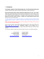
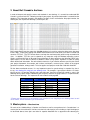
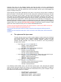
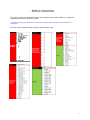
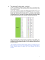
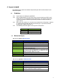
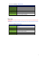
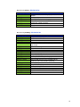
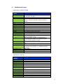
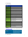
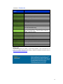
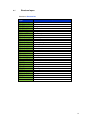
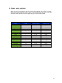
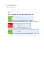
Norms and standards for computer-aided
design (CAD) for Bell Canada
(Version Française disponible)
Version 6.2
July 2013
** TABLE OF CONTENTS **
Introduction
3
About Bell Canada’s archives
4
Master-plans: the structure
5
Layers in detail
8
The color code
15
Delivery of drawings
16
Important guidelines to follow - important
17
The most common mistakes - important
18
Frequently asked questions F.A.Q.
19
2
1. Introduction
This document is written for all Bell Canada consultants, who, in accordance with their contracts, must
use the software AutoCAD as a tool for computer-aided design. This user manual explains the technical
standards required to comply with the requirements of Bell Canada's computer-aided design.
Bell Real Estate Services (BRES) generates approximately 2000 projects every year. These projects
require about 1400 drawings; they include architectural, mechanical, electrical, and/or furniture. It goes
without saying that the whole procedure must be regulated. Throughout the course of this document, you
will find a detailed explanation regarding layers, their respective nomenclature, and the use of official title
blocks, electrical legends and furniture plans. In addition, we have included techniques for technical
drawings that one must respect, the process to follow when sending drawings, frequently asked
questions and a list of common mistakes.
**In order to avoid loss of time and unnecessary work, it is very important to consult the section entitled
“Important guidelines to follow”. In addition, it is imperative to read all notes which are written in blue and
in red.
Please note that after trying unsuccessfully twice to get the drawings up to standards you will be referred
to your SNC Lavalin O&M Project Manager.
All necessary tools needed to implement Bell Canada’s drawing standards can be found on SNC Lavalin
O&M’s
web
site
in
the
‘CAD
Standards’
section.
The
direct
link
is:
http://www.snclavalinom.com/en/cad.aspx . This site contains, among others, the title blocks, menus,
standards (PDF version), electrical legends & symbols, Bell Canada’s CTB and the LAS files for each
discipline.
For all questions related to standards, please do not hesitate to contact us at the following coordinates:
François Laberge
CAD/RESUS Manager Québec
87 Ontario Street, West
Montréal, Qc. H2X 0A7
Tél : 514-840-8388
[email protected]
Jean-François Denis
CAD/RESUS Technician
87 Ontario Street, West
Montréal, Qc. H2X 0A7
Tél : 514-840-8130
[email protected]
3
2. About Bell Canada’s Archives
In order to interpret and apply the norms and standards in our drawings, it is essential to understand Bell
Canada’s system of archives. Following receipt of your project, all pertinent information is entered into the
database. The information entered in the database includes, and is not limited to: the project number, the
drawing title, the sequence of drawings, the discipline, etc.
Bell Canada Real Estate has more than 100,000 drawings in its archive, where the oldest ones date back
to the 1920’s. Project plans dating from before 1998 and which are hand drawn, have been scanned and
stored as TIFF files. The TIFF format allows us to keep the maximum quality while having reasonable file
sizes. In addition, TIFF files can be viewed on any computer using the Windows operating system.
Simply use Microsoft Paint or Microsoft Picture Manager for those who have the Microsoft Office suite.
Upon request, we are able to conduct a database search using specific keywords in order to quickly
obtain the desired information. Do not hesitate to contact us if you need to reference specific plans within
your project framework; for example: wall sections and details, structural plans, details of the original
generator installation, amongst more. This also applies to all projects made after 1998 with AutoCAD.
For the above-mentioned reasons, it is very important to email us your drawings in separate files; that is
to say, one drawing file (.dwg) per one drawing sheet. For example, if your project contains 15 sheets,
please send us 15 separate .dwg files plus your title page. Your files will then be named as seen in the
following table: project number, followed by the discipline, and then the page number, in sequential order,
for the series of drawings. The sequence will not include the title page 00.
Mecanical
Project
Electrical
Project
Architectural
Project
Furniture Layout
Project
10065837m00
10065837m01
10065837m02
10065837m03
10065837m04
10065837m05
10065837m06
10065837m07
10065837e00
10065837e01
10065837e02
10065837e03
10065837e04
10065837e05
10065837a00
10065837a01
10065837a02
10065837a03
10065837a04
10065837a05
10065837a06
10065837fu00
10065837fu01
10065837fu02
**Please note that projects not conforming to our structure of ‘one .dwg file per one drawing sheet’ as well
as file names, will be returned to you for corrections.
3. Master-plans – the structure
For each of the 1,200 buildings in Quebec and Ontario as well as everywhere else in Canada there is a
master plan for the architectural, furniture, mechanical, and electrical sets including a single line diagram.
As described above, these plans are found in separate AutoCAD files as opposed to one drawing file.
4
Currently, these plans are not complete; however, over time, our goal is to have a comprehensive
collection of master plans by floor, building and discipline. With your help, this has become a reality in
several buildings. We started with partial plans that have become, over the years and throughout the
projects, thorough master plans.
At the beginning of your project, depending on your needs, we are able to send you either a complete or
partial set of plans. If the plan does not exist, we will send you the architectural master plan (we have
them all) and thereafter, we will create a new plan reflecting your project. Our goal is to either create a
new master plan or to update existing master plans from the information contained in your project. It is
essential to work with the architectural master plan that we send you, and especially, to never move it
from its point of origin (0,0,0) which is found in the center of the environment. This origin point is the
fundamental link of our reference system as it determines the master plan locations of all disciplines as
well as the title blocks. For all the disciplines, the architectural master plan must be placed in the drawing
using the 'Bind / Insert' command. No Xrefs will be accepted. The title blocks must be inserted in 'Paper
Space' view. Please note that all our plans are saved in AutoCAD 2010 version.
**Please note that all projects with reference files will be returned. In other words, XREF’s will be sent
back for corrections without even opening them first.
**Pease note that master plans which have been moved from their origin point will be returned for
correction.
**Please note that incomplete master plans, which are found to have deleted parts, will be returned for
corrections.
PKN
The system and the layer names
The plans that you return to us will be used to update or create master plans relating to
your particular discipline. When a partial or complete master-plan is sent to you, it will
have specific layers such as: ARINTE, ARDIME, ARBASE, AMTECK, FUTEKN,
ELSERV, ELEQUI, MEGAIN. These names are structured in such a way to identify a
discipline and its content.
•
•
•
•
Layer names for architecture begin with AR.
o ARINTE = Interior walls/architecture
o ARAXES = Axes/architecture
o ARSYMB = Room & Door numbers/architecture
Layer names for electricity begin with EL.
o ELSERV = Services/electricity
o ELALAR = Alarm equipment/electricity
o ELLIGH= Lighting equipment/electricity
Layer names for mechanical begin with ME. Please refer to the section ‘Layers
in details’, as there are sub-categories for this discipline.
o MVDIFF = Diffusers/mechanical
o MENOTE = General notes/mechanical
o MCSUPP = Supply/mechanical
Layer names for furniture begin with FU.
o FUTEKN = Teknion Furniture Systems/furniture
o FUSCRE= Acoustical panels/furniture
o FUCOLU= Columns/furniture
In the following section entitled ‘Layers’, you will find the primary layers used, along with their detailed
names and their respective meaning. Our system is user-friendly and easy to understand. This allows for
new layers to be created, as long as they respect the nomenclature of our system. Examples of layers
that conform to our nomenclature are as follows:
o
o
o
o
ELNOTE-CHGC: = Notes/electricity
ELNOTE-UNIL = Notes/electricity
MVNOTE-DUCT-SUPP- = Notes/ventilation
MVNOTE-DUCT-RETU = Notes/ventilation
5
o
o
MPSANI-PP = Drainage/plumbing
ARDETA-3M = Details/architecture
.
This process allows for considerable leeway when organizing your various entities in a simple and
comprehensible manner within our system.
**Please note that projects which do not meet our nomenclature standards will be returned for
corrections.
Here are a few examples to follow (in green) and to avoid (in red);
6
PKO
The system and the layer names – continued
In order to standardize the drawings created by different users, and to allow for easy
access as well as to maintain a bank of master plans for each discipline; everyone must
meet the following method.
The first step is to identify all elements to be demolished and transfer these to a new
layer with the same name and add the letter –D (for demolition) at the end. For instance,
partitions to be demolished would be named: ARINTE-D. Similarly, all newly designed
elements (walls, electrical services, ventilation ducts…) must be drawn on layers labelled
–N (for new construction). For example, new sprinkler heads must be drawn on a layer
name MSHEAD-N. This system allows us to quickly identify the items to be removed
and those to merge to the existing layers, therefore, creating the new master plan.
Upon receipt of your project, all layers labelled –D are deleted. All layers labelled –N are
merged to existing layers. All new layers which you have created, in accordance with the
nomenclature as described above will remain as is. This method will be use to create
new Master Drawing and will replace the old one. It will be archived for future needs and
to serve as reference.
**Do not hesitate to download the project examples present in our toolbox found on our
web site. With these, you will have a clear understanding of how to perfectly apply Bell
Canada’s drawing standards. In addition, many of your questions will surely be
answered.
7
4. Layers in detail
The following pages outline the method of implementing the official nomenclature for the
different disciplines.
QKN
Guidelines
QKNKN
QKNKO
QKNKP
QKNKQ
Layer names must always be capitalized
You can download the .LAS file (‘layer state’) for each discipline on SNC Lavalin
O&M’s web site (‘Cad Standards’ on the Home page). The contents of these files
can then be directly inserted into your drawing in order to create all the official
layers at once.
When you start a project, it is not necessary to rename the existing layers; however,
it is pertinent that you add extensions to the new layers. If you wish to rename
existing layers, add the extension –E.
The following convention applies to all layers for all disciplines:
Layers
XXXXXX-N
XXXXXX-D
XXXXXX-E
QKO
Description
New construction
Demolition
Existing
Mechanical layers
Mechanical general- Mechanical.las
Mechanical Layers
MEBASE
MEDETA-XXXX
MEDIME
MEHATC
MENOTE-TEMP
MENOTE-XXXX
MENOTE-LEGE
MEREVI
METEXT
Description
Insert architectural drawing on this layer
Details – may be sub-divided into multiple layers
Dimensions
Hatch
General notes which are not found on master plans.
(For the construction only).
Notes on drawing – may be divided into sub-layers and
must always start with MENOTE, e.g.: MENOTE-REVI,
MENOTE-DEMO, MENOTE-CONS…
Schedules and legends
Guide lines, revision clouds
Text and attributes for title block
Mechanical sprinklers - Mechanical.las
Sprinkler Layers
MSDIME-XXXX
MSEQUI
MSHATC
MSHEAD
MSNOTE-XXXX
MSPIPE
Description
Dimensions related to sprinkler (can be sub-divided)
Equipment (pump, valves...)
Hatch
Sprinkler heads
General notes which are not associated to the
sprinkler network but related to sprinklers
Piping network
8
Mechanical ventilation - Mechanical.las
Ventilation Layers
MVACCE
MVCONT
MVDIFF
MVDIME
MVDUCT-RETU
MVDUCT-SUPP
MVEQUI
MVHATC
MVNOTE
MVSYST
Description
Accessories
Controls
Diffusers
Dimensions
Return Ductwork
Supply Ductwork
Equipment
Hatch
General notes which are not associated to ventilation
network but related to ventilation
Systems
Please note:
**Duct work must be drawn in its entirety – that is to say, 2 lines must be used. Nothing else will
be accepted.
**Mechanical plans showing ventilation shafts drawn with one line will be returned for correction.
Mechanical cooling - Mechanical.las
Cooling Layers
MCDIME-XXXX
MCEQUI
MCGLYC
MCHATC
MCNOTE-XXXX
MCRETU
MCSUPP
MCWICE
Description
Dimensions related to cooling equipment; can be subdivided
Cooling equipment
Glycol
Hatching related to the cooling system
General notes that are not associated with the cooling
network but related to cooling
Return
Supply
Ice Water
9
Mechanical heating - Mechanical.las
Heating Layers
MHDIME-XXXX
MHEQUI
MHHATC
MHNOTE-XXXX
MHRETU
MHSUPP
Description
Dimensions related to heating equipment; can be subdivided
Heating equipment
Hatching related to the heating system
General notes that are not associated with the heating
network but related to heating
Return
Supply
Mechanical plumbing - Mechanical.las
Plumbing Layers
MPCOMP
MPCOMB
MPCOND
MPCWTR
MPDIME-XXXX
MPDRAI
MPEQUI
MPFREO
MPFRDR
MPGAZN
MPGAZP
MPHATC
MPHWTR
MPNOTE-XXXX
MPOIL
MPRWTR
MPSANI
MPULTS
MPVALV-XXXX
MPVAPE
MPVENT
Description
Compressed air piping network
Combined
Condensed
Cold water piping network
Dimensions related to plumbing equipment; can be
sub-divided
Rain water drainage
Equipment
Freon
French drain
Natural gas piping network
Propane gas piping network
Hatching related to the plumbing system
Hot water piping network
General notes that are not associated with the
plumbing system but related to plumbing
Fuel oil piping network
Recycled water piping network
Sanitary drainage
Ultrasound
Valves – can be sub-divided into multiple layers
Vapour
Vents
10
QKP
Architectural Layers
Architecture - Architecture.las
Architectural
Layers
ARACCE
ARAXES
ARBASE
ARBUIL
ARCEIL
ARDETA-XXXX
ARDIME
ARFRAM
ARFLOR
ARHATC
ARINTE
ARINTE-FENC
ARINTE-TEMP
ARNOTE-TEMP
ARNOTE-XXXX
ARPLUM
ARREVI
ARROOF-XXXX
ARSYMB-DOOR
ARSYMB-ROOM
ARTEXT
Description
Accessories, ladders, cable holes, concrete foundation
for equipment, foot grilles…
Column grid
All structural elements- exterior walls & doors, windows,
columns, staircases, elevators, vertical shafts, fire
cabinets…
Built-in furniture
Ceiling grid
Details – can be sub-divided
Dimensions
Title block, key plan, north arrow
Raised floor
Hatching
Non-structural interior walls & doors
Interior fence partitions
Temporary walls
General notes which are not found on master plans.
(For the construction only).
Notes on drawing- can be sub-divided and must
always begin with ARNOTE e.g. ARNOTE-PLUM,
ARNOTE-DEMO, ARNOTE-CONS…
Plumbing fixtures found on architectural plans e.g. WC,
sink…
Revision clouds, guide lines
Roofing elements – can be sub-divided and must
always begin with ARROOF e.g. ARROOF-DRAI for
roof drains
Door numbers
Room numbers
Title block text
Architecture – Site.las
SITE PLAN
LAYERS
ARSITE
ARSITE-BASE
ARSITE-BLDG
ARSITE-BORD
ARSITE-DIME
ARSITE-ELEC
ARSITE-EQUI
ARSITE-FENC
ARSITE-HATC
ARSITE-NOTE
ARSITE-PAVE
ARSITE-PLNT
ARSITE-PROP
Descriptions
Site Plan
Concrete base
Building outline
Border
Dimensions
Electrical - Streetlights, outlets, etc…
Equipment – manholes, petrol pumps, telephone poles,
etc…
Fence
Hatching
Notes
Parking lots
Plants & landscaping
Property line, survey benchmark
11
QKQ
Electrical layers
Electrical - Electrical.las
ELECTRICAL
LAYERS
ELACCE
ELALAR
ELBASE
ELCHGC
ELCOMM
ELCONT
ELDETA-XXXX
ELDIAG
ELDIAG-XXXX
ELDIME
ELEQUI
ELEMER
ELHATC
ELHEAT
ELLIGH
ELMALT-AC
ELMALT-DC
ELMONI-BATT
ELMONI-BCPM
ELMONI-ELEC
ELMONI-UPS
ELNOTE-TEMP
ELNOTE-XXXX
ELNOTE-LIGH
ELNOTE-CONT
ELNOTE-COMM
ELNOTE-SECU
ELNOTE-LEGE
ELNOTE-UNIL
ELREVI
ELSECU
ELSERV
ELTEXT
Description
Accessories
Alarm equipment & devices
Insert the architectural plan on this layer
UPS & DC equipment related to telecommunications
Communication equipment & devices
Control
Details – may be sub-divided
Single line diagram
Single line diagram- may be sub-divided
Dimensions
Panels, transformers, distribution center
Emergency equipment
Hatching
Heating equipment and wiring
Lighting equipment
MALT Network– grounding of the alternating current
MALT Network– grounding of the direct current
Monitoring system of UPS batteries
Monitoring system of UPS circuit panels
Monitoring system of the electrical network
Monitoring system of UPS
General notes which are not found on master plans.
(For the construction only).
Notes on the drawing- may be sub-divided and must
begin with ELNOTE e.g. ELNOTE-BATT, ELNOTEDEMO, ELNOTE-CONS…
Lighting notes
Control notes
Communication notes
Security notes
Schedules and legends
Notes or dimensions relating to the single line diagram
Revision clouds, guide lines
Security
Feeder or Bypass panels only, electrical transformers
and electrical distributions
Text and attributes in title block
Please note:
For electrical legends and symbols, a menu will be required. This can be found in our toolbox and
inserted directly into the drawing.
Follow the installation instructions found at
http://www.snclavalinom.com/en/cad.aspx .
QKR
Furniture Layers
12
Furniture - Furniture.las
Furniture
Layers
FUBASE
FUDETA
FUDIME
FUELEC
FUELEC-POLE
FUEQUI
FUFINI
FUHATC
FUHAWO
FUORGA
FUNAME
FUNOTE-TEMP
FUNOTE-XXXX
FUPOSI
FUREVI
FUSCRE
FUSCRE-TEKN
FUSCRE-STEE
FUSCRE-HAWO
FUSTAN
FUSTEE
FUTEKN
FUTEXT
XXXXXX-ATT
Description
Insert the architectural plan on this layer
Details
Dimensions
Electrical furniture components
Electrical pole layout
Equipment
Finishes
Hatching
Haworth Furniture
Organization Code
Individuals’ names
General notes which are not found on master plans.
(For the construction only).
Notes on the drawing- may be sub-divided and must
begin with FUNOTE e.g. FUNOTE-EQUI, FUNOTEDEMO, FUNOTE-CONS…
Workstation number
Guide lines, revision clouds
Acoustical panels
Acoustical panels Tecknion
Acoustical panels Steelcase
Acoustical panels Haworth
Standard furniture & equipment (all other furniture)
Steelcase Furniture
Teknion Furniture
Text & attributes for the title block
Attributes- can be added to any layer
Please note:
For furniture legends and symbols, a menu will be required. This can be found in our
toolbox and inserted directly into the drawing. Follow the installation instructions found at
http://www.snclavalinom.com/en/cad.aspx .
13
QKN
Structure layers
Structure- Structure.las
Structure
layers
STSTEE-COLU
STSTEE-CONT
STSTEE
STSTEE-META
STSTEE-BEAM
STSTEE-GIRD
STFRAM-STRI
STFRAM-BARS
STCONC
STCONC-BASE
STCONC-COLU
STCONC-PAVI
STCONC-HATC
STCONC-WALL
STCONC-BEAM
STCONC-SAW
STCONC-WIRE
STWOOD-COLU
STWOOD
STWOOD-BEAM
STWOOD-TRUS
STAXES
STDETA
STDIME
STHATC
STOPEN
STTEXT
STNOTE
STFOND-EMPA
STFOND-PICK
STREVI
Descriptions
Steel columns
Steel braces
Steel general
Metallic deck
Steel beams
Steel girders
Columns strips
Framework bars
Concrete general
Concrete bases and pilasters
Concrete columns
Concrete paving stones
Hatching for concrete cross sections
Concrete walls
Concrete beams
Saw cuts in the concrete slab
Wire-mesh in the concrete slab
Wooden columns
Wood general
Wooden beams
Wooden joists and trusts
Axes lines and bubbles
Cross sections and details
Dimensions
Hatch general
Opennings
Text, annotations
General notes
Footings
Pickets
Révisions
14
5. Colour code- optional
When you receive a master plan, all layers will have the properties set to “ByLayer” and all
objects/lines/points/annotation will be in white. The choice of colours for layers is left to the
discretion of the individual user. We suggest that you use the following table.
Colour
Red
Code
1
Thickness (mm)
0.180
Thickness (in)
0.007
Yellow
2
0.254
0.010
Green
Cyan
Blue
Magenta
White
Grey
Dark Red
Dark Yellow
Dark Green
Dark Cyan
Dark Blue
Dark Magenta
Dark Grey
3
4
5
6
7
8
12
50
106
151
172
214
252
0.300
0.350
0.500
0.600
0.700
0.080
0.800
1.000
1.200
1.400
0.180
0.254
0.180
0.012
0.014
0.020
0.024
0.028
0.003
0.031
0.039
0.047
0.055
0.007
0.010
0.007
15
6. Delivery of drawings
By email - directions:
When returning files by email, they must be sent to the following address:
[email protected]
When sending an email, please write the following information (exactly as shown) in the Subject
line:
AsBuilt – Location Code – Address, City –SNC Lavalin O&M’s project number
This guideline is very important as we archive all emails received. This allows us to easily search
for information using the project number and/or address.
For large files, send the plans into sequential emails and mark them as such:
** Sent items that do not strictly comply with this directive will be returned for corrections.
16
7. Important guidelines to follow – very important
TKN
TKO
TKP
TKQ
TKR
TKS
TKT
TKU
TKV
TKNM
TKNN
TKNO
TKNP
TKNQ
TKNR
At the beginning of a new project, consultants from all disciplines must ask for a new
master plan. This ensures that they will work with the most current information.
You should never crop or delete parts of the master plan. Use the ‘Layout’ mode in order
to isolate sections thereof.
**Please note that incomplete master plans where parts have been deleted will be
returned for corrections.
All Bell Canada drawings have an insertion point of 0,0,0 and this should not be
modified. The plans are not to be moved as our system is based on this insertion point.
Due to this insertion point, all plans, from all disciplines, fit perfectly within the
architectural plan. Furthermore, the insertion point allows for our plans to be perfectly
aligned within our title blocks A0 and A1.
**Please note that master plans displaced from their origin point will be returned for
corrections.
Some consultants like to work with different floors on one sheet, you will understand that
our master drawing system does not aloud that practice, therefore do not hesitate to
create more sheet even though the real estate isn’t fully used.
**Please note that any drawing that uses more than one floor will be returned for
corrections.
Some consultants like to work using multiple copies of the architectural plans within
model space; for example, construction & demolition or existing & proposed. This kind of
layout is unacceptable since this will move the origin point of the plan, see section 7.3.
Please work with one single plan, with all information found within it. This is possible due
to the layer tool (filter/freeze layers in “Layout” mode). It is very important to use the
following system: construction, demolition, existing.
** Plans which do not follow this direction will be returned for corrections.
All Bell Canada projects must be drawn with the official title blocks available at the
following address: http://www.snclavalinom/en/cad
**Plans not respecting this direction will be returned for corrections.
The measurement system for Bell Canada’s projects is the official system declared by
the Canadian Government, that is to say, the metric system.
** Plans drawn to the imperial system will be returned for corrections.
If you create blocks, they must have properties of ‘ByLayer’. Each element inside the
block must be on a standard layer and not on layer 0.
Standard blocks found in the furniture and electrical menus have been created to be able
to modify them without having to explode them. Therefore, leave them intact as much as
possible as this keeps the drawing light.
Hatches or fills must be set to the layers relating to the corresponding discipline; for
example: architecture ARHATC, furniture FUHATC, electrical ELHATC…
SNC Lavalin O&M’s project number, address, location code, project and drawing title
must all be included in the title block in order to ease the archiving of drawings.
Bell Canada’s title page and title blocks (available online ‘Toolbox’) must be used for all
projects.
One copy of each file must be in .DWG 2010 format. Each page of the As Built project
must be saved separately; that is to say, if the project has 5 pages, you must send us 5
separate files.
Please purge completely your drawings before sending it to us.
The drawings must not contain 3D Items of any kind (3D faces, 3D solids, 3d...)
**Please note that drawings containing 3D items will be returned for corrections
17
8. The most common mistakes.
UKN
UKO
UKP
UKQ
UKR
UKS
UKT
UKU
UKV
UKNM
The master plan has been moved. Please do not move the insertion point or the
drawing. Mecanical, electrical, architectural and furniture plans are aligned on this point.
Use the furniture and electrical menus available to you. This is important because when
you insert the block, it will create the proper layers automatically.
The system of units has been changed and the plan is drawn with the imperial
system. Do not change the system of units as all our drawings use the metric system.
There is more than one floor on the same drawing. It is imperative to place one floor
per drawing. You may only place parts of other floors for reference only.
There is more than one drawing per file at delivery. Please use one file per drawing
(12 drawings = 12 Autocad files)
Use the ‘Bind’ command and check ‘Insert’ to import the architectural plan in each
drawing.
Parts of the master plan have been deleted. It is very important not to delete parts of a
floor. The entire floor must be present in the ‘model space’. You may select certain parts
in ‘paper space’.
The nomenclature for layers has not been respected. It is very important to respect
the convention created for the organization of layers.
Ventilation ducts were drawn using only one line. All ventilation ducts must be drawn
using 2 lines.
Project information does not conform to the required format in the ‘Subject’ line of
an email message. Details in the subject zone must be formatted as follows :
AsBuilt – location code - Address – City – SNC LAVALIN O&M’s project number
18
9. Frequently asked questions F.A.Q.
VKN
Is there a drawing prototype for SNC Lavalin O&M?
No, because the protocol gives the consultant the freedom to
choose his own method of working when it comes to colours and/or
thickness of lines.
VKO
Must I respect the colour chart?
No, however, if you do not respect the colour codes and we must
plot, the monochrome setting will be used. The purpose of the
colour code is to be able to plot plans with the proper modulation.
VKP
Can I create new layers?
Yes, layer names can be created in order to allow for a better
understanding and usage of your plans. While doing so, it is
essential to respect the nomenclature as described in the section
‘Layer names’.
VKQ
When I use the blocks from the furniture and electrical menus, may I
explode them in order to modify them?
No, blocks have been designed to allow for modifications without
having to explode them. All the modification tools are found in the
menu bar. If you do happen to explode a block, please regroup all
unnecessary lines as these clutter the drawing.
VKR
Can I modify the title block?
No, these title blocks have been approved by our client (Bell) and
must remain as such.
19