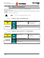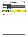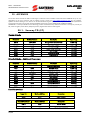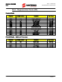
1
• 15G0851Q1 •
DATA LOGGER
ES851
BASIC – ADVANCED
USER MANUAL
-Programming InstructionsIssued on 23/01/09
R. 02
Ver. 1.67x
English
• This manual is integrant and essential to the product. Carefully read the instructions contained herein as they
provide important hints for use and maintenance safety.
• This device is to be used only for the purposes it has been designed to. Other uses should be considered improper
and dangerous. The manufacturer is not responsible for possible damages caused by improper, erroneous and
irrational uses.
• Elettronica Santerno is responsible for the device in its original setting.
• Any changes to the structure or operating cycle of the device must be performed or authorized by the Engineering
Department of Elettronica Santerno.
• Elettronica Santerno assumes no responsibility for the consequences resulting by the use of non-original spareparts.
• Elettronica Santerno reserves the right to make any technical changes to this manual and to the device without prior
notice. If printing errors or similar are detected, the corrections will be included in the new releases of the manual.
• Elettronica Santerno is responsible for the information contained in the original version of the Italian manual.
• The information contained herein is the property of Elettronica Santerno and cannot be reproduced. Elettronica
Santerno enforces its rights on the drawings and catalogues according to the law.
Elettronica Santerno S.p.A.
Strada Statale Selice, 47 – 40026 Imola (BO) Italy
Tel. +39 0542 489711 - Fax +39 0542 489722
www.elettronicasanterno.com [email protected]
BASIC - ADVANCED
PROGRAMMING INSTRUCTIONS
0.
DATA LOGGER
ES851
TABLE OF CONTENTS
0.1.
Chapters
0.
TABLE OF CONTENTS ................................................................................................................................ 2
0.1.
Chapters ................................................................................................................................................... 2
0.2.
Figures ...................................................................................................................................................... 2
0.3.
Tables ....................................................................................................................................................... 3
1.
OVERVIEW ................................................................................................................................................. 4
1.1.
Main Features............................................................................................................................................ 4
1.2.
How to Use this Manual ............................................................................................................................. 4
2.
FIRST STARTUP ........................................................................................................................................... 5
2.1.
Connections .............................................................................................................................................. 5
2.1.1. Connection to the Link Service................................................................................................................ 6
2.1.2. LAN Connection .................................................................................................................................... 6
2.1.3. Connection via GSM Modem or Analog Modem ..................................................................................... 7
2.2.
ES851 Status Display.................................................................................................................................. 7
2.3.
Setting the Routing Table ............................................................................................................................ 7
2.4.
Programming the LOGGING Function ........................................................................................................ 7
2.5.
Parameter Save.......................................................................................................................................... 8
3.
MENU LIST ................................................................................................................................................. 9
3.1.
Menus and Submenus .............................................................................................................................. 10
3.1.1. Synoptic Table for M Measures............................................................................................................. 10
3.1.2. Synoptic Table for P, R, I, C Parameters ................................................................................................ 10
3.2.
List of the BASIC Measures and Parameters ............................................................................................... 12
3.3.
List of the ADVANCED Measures and Parameters ...................................................................................... 14
4.
DATA LOGGER MENU .............................................................................................................................. 16
5.
DATA LOGGING CONSOLE MENU .......................................................................................................... 20
6.
SCAN DEVICE 11-40 MENU ..................................................................................................................... 29
7.
UPLOAD CONSOLE MENU....................................................................................................................... 33
8.
LOG MONITOR MENU ............................................................................................................................. 34
9.
EVENT MONITOR MENU .......................................................................................................................... 37
10.
MODBUS CONFIGURATION MENU ..................................................................................................... 40
11.
CONNECTION CONFIGURATION MENU ............................................................................................ 41
12.
TCP/IP PROXY CONFIGURATION MENU.............................................................................................. 45
13.
REAL TIME DATA MENU....................................................................................................................... 46
14.
MODEM CONFIGURATION AND STATUS MENU ................................................................................. 47
15.
SMS MENU .......................................................................................................................................... 48
16.
CLOCK/CALENDAR MENU................................................................................................................... 50
17.
ROUTING TABLE Æ ZONE MENU ........................................................................................................ 55
18.
ROUTING TABLE 1-10 MENU............................................................................................................... 57
19.
DOWNLOAD CONSOLE MENU ........................................................................................................... 59
20.
APPENDIX ............................................................................................................................................ 60
20.1.
Sunway TG (ST)........................................................................................................................................ 60
20.2.
Sunway M XR (SM) ................................................................................................................................... 61
20.3.
Smart String Box (QF)............................................................................................................................... 62
20.4.
Penta Drive (PD)....................................................................................................................................... 63
20.5.
Multipump Penta (PM) .............................................................................................................................. 64
20.6.
Regenerative Penta (PR) ............................................................................................................................ 65
20.7.
String Box (QS) ........................................................................................................................................ 66
0.2.
Figures
Figure 1: The RemoteDrive/Sunway UPLOAD Console. ................................................................................................ 33
Figure 2: SMS format. ................................................................................................................................................ 48
Figure 3: DOWNLOAD Console as displayed in the RemoteDrive/Sunway. ................................................................... 59
2/66
DATA LOGGER
BASIC – ADVANCED
PROGRAMMING INSTRUCTIONS
ES851
0.3.
Tables
Table 1: Default configurations of the available connections........................................................................................... 5
Table 2: Menu List........................................................................................................................................................ 9
Table 3: List of the BASIC measures and parameters.................................................................................................... 13
Table 4: List of the ADVANCED measures and parameters........................................................................................... 15
Table 5: List of the parameters and measures in the Data Logger menu........................................................................ 16
Table 6: List of the parameters and measures in the Data Logging Console menu......................................................... 21
Table 7: Bit-map of the devices boxed after SCANNING. ............................................................................................. 27
Table 8: Bit-map of the recognized devices.................................................................................................................. 27
Table 9: Bit-map of the type of logging for the connected devices................................................................................. 27
Table 10: Bit-map for Event 0 firing for the connected devices. ..................................................................................... 28
Table 11: List of parameters and measures, Scan Device 11-40 ................................................................................... 29
Table 12: Bit-map of the devices boxed after SCANNING. ........................................................................................... 30
Table 13: Bit-map of the recognized devices................................................................................................................ 31
Table 14: Bit-map of the type of logging. .................................................................................................................... 31
Table 15: Bit-map of Event 0 fired for the connected devices. ....................................................................................... 32
Table 16: List of the measures in the Log Monitor menu............................................................................................... 34
Table 17: Bit-map of the Log Status............................................................................................................................. 35
Table 18: List of the measures in the Event Monitor menu. ........................................................................................... 37
Table 19: Bit-map of the Log Status............................................................................................................................. 37
Table 20: Default settings for serial ports COM1 and COM2. ...................................................................................... 40
Table 21: Parameter in the Modbus configuration menu. ............................................................................................. 40
Table 22: List of the parameters in the TCP/IP Configuration menu............................................................................... 41
Table 23: List of the parameters in the TCP/IP Proxy Configuration menu...................................................................... 45
Table 24: Parameter in the Real Time Data menu. ....................................................................................................... 46
Table 25: Parameter in the Modem Configuration menu.............................................................................................. 47
Table 26: List of the measures and parameters in the SMS menu.................................................................................. 48
Table 27: List of the measures and parameters in the Clock/Calendar menu. ............................................................... 50
Table 28: Conventional MODBUS addresses............................................................................................................... 55
Table 29: List of the measures and parameters in the Routing Table ---> ZONE menu. ................................................. 55
Table 30: List of the parameters in the Routing Table menu.......................................................................................... 57
3/66
BASIC - ADVANCED
PROGRAMMING INSTRUCTIONS
1.
DATA LOGGER
ES851
OVERVIEW
1.1.
Main Features
ES851 Data Logger board allows logging weather variables and operating variables of a photovoltaic (industrial) plant
and allows interfacing the PV plant to a supervisor computer, even a remote computer, through different connecting modes
for data logging and monitoring of the devices connected to the PV plant.
Data is logged to 7 files (Log 1, Log 2, Log 3, Log 4, Log 5, Log 6, Event Log) and can be used to create a database that
can be displayed and graphically represented through the RemoteDrive/Sunway software provided by Elettronica Santerno
(see “How to Use this Manual” below).
ES851 Data Logger board can be handled through dedicated parameters that are divided into menus and submenus.
Each menu includes programmable parameters, measures, and commands.
Data/information is exchanged through COM1 and COM2 serial ports provided with ES851, through the Ethernet socket
for a LAN and the Internet, or through a modem connection.
1.2.
How to Use this Manual
This manual covers functionality and first startup of ES851 Data Logger board.
The RemoteDrive/Sunway software provided by Elettronica Santerno allows full exploitation of ES851 Data Logger
functionality. The RemoteDrive/Sunway allows the following functions:
•
image acquisition;
•
oscilloscope functions and multifunction tester functions;
•
table compiler and displayer including operation data log;
•
parameter setup and data reception-transmission-storage from and to a computer;
•
scan function for the automatic detection of the connected devices (up to 247 devices may be connected).
You can also create your own dedicated software. This manual provides any information concerning addressing (Address
field) and scaling (Range field) for interfacing with the Data Logger.
Some of the operations above can be performed via serial link, through standard RS485 port of the inverter where ES851
is installed, or using the display/keypad unit.
This manual covers the parameter settings as displayed by the RemoteDrive/Sunway; functions implemented in the
display/keypad as well are highlighted accordingly. For more details about functionality of the display/keypad, please refer
to the Programming Instructions manuals relating to the inverters provided with ES851 Data Logger board.
4/66
DATA LOGGER
BASIC – ADVANCED
PROGRAMMING INSTRUCTIONS
ES851
2.
FIRST STARTUP
This section outlines the basic setup of ES851 Data Logger board with reference to the parameterization detailed in the
sections below. You can use the RemoteDrive/Sunway from a computer connected in local mode to ES851 via COM1
(which is factory set as RS232, Modbus slave).
The first startup of ES851 control board consists of two steps:
1. Connection configuration (see Connections below);
2. Configuration of the data acquisition function (see Setting the Routing Table and Programming the LOGGING
Function).
2.1.
Connections
ES851 Data Logger board can be connected to a computer in one of the following modes:
•
Local mode: through COM1 and COM2 ports—RS232, RS485 or Ethernet port—for a direct LAN;
•
Remote mode: through the Ethernet port or a GPRS modem, both connected via the Internet, or through an
analog modem or a GSM modem for point-to-point connections.
The following sections explain how ES851 is started when using connecting modes other than the default modes, which are
given in the table below.
Note that all parameters relating to ES851 connections are R parameters, which are read and acquired only after resetting
ES851 Data Logger board.
NOTE
Configurations other than the default connections can be required when ordering the
equipment.
CONNECTION
DEFAULT CONFIGURATION
COM1
RS232 in Modbus Slave mode
COM2
RS485 in Modbus Master mode
Ethernet
Link Service with DHCP and DNS
Table 1: Default configurations of the available connections.
5/66
DATA LOGGER
BASIC - ADVANCED
PROGRAMMING INSTRUCTIONS
2.1.1.
ES851
C ONNECTION
TO THE
L INK S ERVICE
The connection via the Internet to the Link service is the default connecting mode. The connection to the Link service can be
implemented as follows:
1)
Using a router: in that case, no alteration to the default parameters is required;
CAUTION
2)
Using a GPRS modem: in that case, the following modifications are required:
•
Connect ES851 to a computer via COM1 port (RS232 Modbus RTU);
•
Set parameter R450 as “2: PROXY GPRS modem” (see the “CONNECTION CONFIGURATION MENU”);
•
In the parameters relating to the APN (P3110-P3139), enter the APN of the provider, such as
“ibox.tim.it” (see the “CONNECTION CONFIGURATION MENU”);
•
Set the PIN of the SIM card being used in parameter R287, which is included in the “MODEM
CONFIGURATION AND STATUS MENU”;
•
Save the parameters you have changed (see the “Parameter Save” section);
•
Reset the Data Logger so that new settings will take effect.
2.1.2.
LAN C ONNECTION
CAUTION
6/66
The connection to the Link service requires the DHCP in the network where ES851
Data Logger board is installed. If the DHCP is not available, disable the DHCP via
parameter R450 in the TCP/IP PROXY CONFIGURATION MENU by selecting one
of the options that do not require using this protocol (e.g. “5: PROXY Ethernet (No
DHCP, DNS )”, “6:PROXY Ethernet (No DHCP, No DNS )”), then enter the static IP
address, the IP mask and the Gateway in the CONNECTION CONFIGURATION
MENU.
The LAN administrator must reserve a STATIC IP address so that it is uniquely
identified, as a dynamic control of IP addresses can change the association
between the MAC address of the Data Logger and the IP address whenever the
equipment is started. As a result, the address required for communication cannot
be known beforehand.
•
Connect ES851 to a computer via COM1 port (RS232 Modbus RTU);
•
Set parameter R450 = “8: Direct Ethernet” (see the “CONNECTION CONFIGURATION MENU”);
•
Save the parameters you have changed (see the “Parameter Save” section);
•
Reset the Data Logger so that new settings will take effect.
DATA LOGGER
BASIC – ADVANCED
PROGRAMMING INSTRUCTIONS
ES851
2.1.3.
C ONNECTION
VIA
GSM M ODEM
OR
A NALOG M ODEM
•
Connect ES851 to a computer via COM1 port (RS232 Modbus RTU);
•
In parameter R450, choose the type of modem being used by selecting “3: Direct GSM modem” or “4: Direct
Analog Modem” (see the CONNECTION CONFIGURATION MENU);
•
If you are using a GSM modem, enter the PIN of the SIM card in parameter R287 (see the CONNECTION
CONFIGURATION MENU);
•
Save the parameters you have changed (see the “Parameter Save” section);
•
Reset ES851 so that new settings will take effect.
If you are using a GSM modem, you can set a mobile phone number receiving SMS when Events fire (see the SMS MENU).
2.2.
ES851 Status Display
From the DATA LOGGER MENU, you can display the status of ES851, which is programmed with factory settings. In
particular, the MAC address is displayed.
Make sure that no alarm trips. If so, try to reset the alarm; if the alarm persists, please contact Elettronica Santerno.
2.3.
Setting the Routing Table
The routing table defines the map where the identifier of each device connected to the Data Logger through a given
transmitting device matches with the virtual identifier which the connected device responds to through the Data Logger
itself. In that way, the networked devices can also connected to different apparatuses and can be controlled exactly in the
same way via the Data Logger.
The Routing Table is preset for the automatic detection of the devices connected to RS485 serial link (COM2), if their
identifiers have been previously set to values higher than or equal to 3. Unique identifiers are to be assigned to avoid
conflicts. According to factory settings, COM2 port is already set as Master Modbus, thus allowing handling all the
connected devices. Each address mapped in the table is enabled by default.
The ROUTING TABLE Æ ZONE MENU can be used for easier programming of ES851 controlling very complex plants.
2.4.
Programming the LOGGING Function
The default LOGGING parameters have been studied by Elettronica Santerno’s technicians in respect to the variables to be
monitored (see APPENDIX). As a result, no modification is required for the DATA LOGGING CONSOLE MENU.
If the number of devices connected to ES851 is limited, an extended (C161) LOGGING can be performed, allowing
monitoring more variables than factory-set variables.
Once the type of LOGGING is selected, activate the SCANNING of the connected devices through I160, allowing
detecting the acronym and the routing address for all the devices connected to ES851. Measure M5049 displays the status
of the LOGGING commands allowing checking if they are correct.
After sending the SCAN command, ES851 performs automatic settings of the parameters for the monitoring of the device
variables (BOXING).
If no LOGGING is required for some of the detected devices, they can be excluded by setting the ‘Type’ field of parameters
C165-C180 and C480-C503. BOXING will be automatically performed by ES851 based on the new information.
You can now start LOGGING through I160. From the LOG MONITOR MENU and the EVENT MONITOR MENU, check if
LOGGING is correct.
To view the logged data, follow the procedure explained in the UPLOAD CONSOLE MENU.
7/66
DATA LOGGER
BASIC - ADVANCED
PROGRAMMING INSTRUCTIONS
ES851
NOTE
LOGGING is to be activated as the last installation step. Any procedure for the
connection configuration (see sections below) must be performed before LOGGING is
activated.
NOTE
The type of LOGGING (extended or standard logging) can be changed for any boxed
device.
To sum up, do the following to activate the LOGGING function in the “DATA LOGGING CONSOLE MENU”:
•
Select the type of LOGGING from parameter C161;
•
Press the SCAN button;
•
Activate LOGGING , I160 “ENABLE All Logs”.
2.5.
Parameter Save
After entering the new settings, execute the Eeprom command “5: Save All” (see the “DATA LOGGER MENU”) to keep
them stored even after ES851 is reset. If you are using the RemoteDrive/Sunway software, just press the S key after
changing a parameter, or send the Save All Command.
8/66
DATA LOGGER
BASIC – ADVANCED
PROGRAMMING INSTRUCTIONS
ES851
3.
MENU LIST
The menu list and the main features of each menu are contained in Table 2 below. Each menu is then detailed on the
following pages.
MENU
FUNCTIONALITY
Data Logger
Main measures and functions of ES851
Data Logging Console
Console for the main logging functions
Scan Device 11-40
Console displaying the connected devices whose IDs range from 11 to 40
Upload Console
Console for the acquisition of stored data from ES851
Log 1 Monitor
Log 1 status
Log 2 Monitor
Log 2 status
Log 3 Monitor
Log 3 status
Log 4 Monitor
Log 4 status
Log 5 Monitor
Log 5 status
Log 6 Monitor
Log 6 status
Event Monitor
Event status
Modbus Configuration
Serial port configuration parameters
TCP/IP Proxy Configuration
Configuration parameters for TCP/IP communications with the Link server
Real Time Data
Modem Configuration and
Status
SMS
Configuration parameters for sending real-time data
Clock/Calendar
Console for clock/calendar settings and display
Modem configuration parameters
SMS activation console
Routing Table Æ ZONE
Zone configuration parameters
Routing Table 1-10
Table for the virtual mapping of the devices connected to the Data Logger for IDs 1-10
Download console
Console for uploading files to the Data Logger
Table 2: Menu List.
9/66
DATA LOGGER
BASIC - ADVANCED
PROGRAMMING INSTRUCTIONS
3.1.
ES851
Menus and Submenus
Three programming levels are available. They can be changed by setting P298 accordingly.
BASIC (factory setting): permits to view the main measures and to set parameters P298 (programming level) and allows
changing basic programming;
ADVANCED: permits to access the BASIC parameters and the parameters relating to the programming of the available
connections;
ENGINEERING: allows accessing all parameters.
NOTE
3.1.1.
This manual covers BASIC/ADVANCED parameters only.
S YNOPTIC T ABLE
FOR
M M EASURES
(Read-only)
Mxxx
Range
Level
Measure Name
Address
Function
3.1.2.
Device representation
(integer)
Display on the display/keypad and the
RemoteDrive/Sunway software
(may be a decimal figure)
plus unit of measure
Access Level (BASIC / ADVANCED )
Modbus address which the measure can be read from
(integer)
Measure description.
S YNOPTIC T ABLE
FOR
P, R, I, C P ARAMETERS
(Read-Write)
Pxxx
Range
Default
Level
Parameter Name
Address
Function
10/66
Device representation
(integer)
Display on the display/keypad and the
RemoteDrive/Sunway software (may be
a decimal figure)
plus unit of measure
Parameter factory-setting
Parameter factory-setting (as displayed)
(as represented for ES851 board)
plus unit of measure
Access Level (BASIC / ADVANCED)
ModBus address which the parameter can be read from/written to
(integer)
Parameter description
DATA LOGGER
BASIC – ADVANCED
PROGRAMMING INSTRUCTIONS
ES851
Pxxx Parameters (Always R/W).
Cxxx Parameters (Read-only with LOGGING function activated; R/W with
LOGGING function deactivated).
NOTE
Rxxx Parameters
Always R/W, but they activate only when the device is next
powered on.
Ixxx Inputs
These are not parameters, but inputs (the values assigned to these
inputs are not stored to non-volatile memory. They are always set to 0 when the
inverter is powered on).
11/66
DATA LOGGER
BASIC - ADVANCED
PROGRAMMING INSTRUCTIONS
3.2.
ES851
List of the BASIC Measures and Parameters
MODBUS
Address
298
Menu
Parameter
4 DATA LOGGER MENU
P298
Access Level
I012
EEPROM Command
2003
No Command
M475
Software Version
475
-
M5000
Alarm Condition
5000
-
M5003
Active Access Level
5003
-
M5004
Flash Card Error
-
M5006
MAC Address
5004
5006, 5007,
5008
M5199
Latest EEPROM
executed
M5050
M5057
8 LOG 1 MONITOR MENU
5050
-
Log 1 Status
5057
-
M5070a-b
Year and Month of Activation of Log 1
5070
-
M5071a-b
Day and Time of Activation of Log 1
Minutes and Seconds of Activation of
Log 1
5071
-
5072
-
M5051
Log 2 Length
5051
-
M5058
Log 2 Status
5058
-
M5073a-b
Year and Month of Activation of Log 2
5073
-
M5074a-b
Day and Time of Activation of Log 2
Minutes and Seconds of Activation of
Log 2
5074
-
5075
-
M5052
Log 3 Length
5052
-
M5059
Log 3 Status
5059
-
M5076a-b
Year and Month of Activation of Log 3
5076
-
M5077a-b
Day and Time of Activation of Log 3
Minutes and Seconds of Activation of
Log 3
5077
-
5078
-
M5053
Log 4 Length
5053
-
M5060
Log 4 Status
5060
-
M5079a-b
Year and Month of Activation of Log 4
5079
-
M5080a-b
Day and Time of Activation of Log 4
Minutes and Seconds of Activation of
Log 4
5080
-
5081
-
M5054
Log 5 Length
5054
-
M5061
Log 5 Status
5061
-
M5082a-b
Year and Month of Activation of Log 5
5082
-
M5083a-b
Day and Time of Activation of Log 5
5083
-
M5084a-b
Minutes and Seconds of Activation of
Log 5
5084
-
M5081a-b
8 LOG 5 MONITOR MENU
12/66
-
Log 1 Length
M5078a-b
8 LOG 4 MONITOR MENU
not
BASIC
-
M5075a-b
8 LOG 3 MONITOR MENU
command
Default
5199
M5072a-b
8LOG 2 MONITOR MENU
FUNCTION
DATA LOGGER
BASIC – ADVANCED
PROGRAMMING INSTRUCTIONS
ES851
8 LOG 6 MONITOR
MENU
9 EVENT MONITOR MENU
M5055
Log 6 Length
5055
-
M5062
Log 6 Status
5062
-
M5085a-b
Year and Month of Activation of Log
6
5085
-
M5086a-b
Day and Time of Activation of Log 6
5086
-
M5087a-b
Minutes and Seconds of Activation of
Log 6
5087
-
M5056
Evt Log Length
5056
-
M5063
Evt Log Status
5063
-
5088
-
M5088a-b
M5089a-b
5089
-
Minutes and Seconds of Activation of
Evt Log
5090
-
M5010a
Year
5010
-
M5010b
Month
5010
-
M5011a
Day of the Week
5011
Mon
M5011b
Day of the Month
5011
1
M5012a
Hours
5012
-
M5012b
Minutes
5012
-
M5013
Seconds
5013
-
M5090a-b
16 CLOCK/CALENDAR
MENU
Year and Month of Activation of Evt
Log
Day and Time of Activation of Evt Log
Table 3: List of the BASIC measures and parameters.
13/66
DATA LOGGER
BASIC - ADVANCED
PROGRAMMING INSTRUCTIONS
3.3.
ES851
List of the ADVANCED Measures and
Parameters
MODBUS
Address
Default Setting
Min. Sampling Time
164
-
P229
Initial SCANNING Address
229
1
P230
Final SCANNING Address
230
40
C238
Fast Sampling Only
238
No
C161
Type of Data Logging
161
Standard
C162
Fast Log Sampling Time
162
60 s (1 min)
C163
Fast Log Sample N.
163
1
C245
Fast Log Min. Variation Percent
245
0,0%
C242
C243
C244
Slow Log Sampling Time
Slow Log Sample N.
Slow Log Min. Variation Percent
242
243
244
3600s (1 hour)
1
0.0%
I160
Logger Command
160
No command
5049
-
5016
-
Menu
Parameter
5 DATA LOGGING
CONSOLE MENU
M164
FUNCTION
M5049
LOGGING Command Status
N. of Devices Detected when
M5016
SCANNING
Modbus ID of the Device being
M5017
SCANNED
C165-a ÷ C174-a ID of the Connected Device
5017
-
165-174
C165-b ÷ C174-b Type of Connected Device
165-174
0
No device
detected
-
M214
Connected Device Boxing
214
M215
Recognized Connected Device
Extended
Logging
for
the
Connected Device
Event 0 Fired for the Connected
Device
215
C241
M512
6 SCAN DEVICE 11-40
MENU
C175-a ÷ C180-a
Connected Device ID
C480-a ÷ C503-a
C175-b ÷ C180-b
Type of Connected Device
C480-b ÷ C503-b
M204, M205
Boxing of the Connected Device
M207, M208
C239, C240
M510, M511
10 MODBUS
CONFIGURATION MENU
14/66
R297
Connected Device Recognized
Extended
Logging
for
the
Connected Device
Event 0 Active for the Connected
Device
ES851 Device Id
241
512
Standard logging
for each device
-
175-180
480-503
175-180
480-503
No device
detected
204, 205
-
207, 208
Long standard for
each device
239, 240
0
510, 511
-
297
1
DATA LOGGER
BASIC – ADVANCED
PROGRAMMING INSTRUCTIONS
ES851
11 CONNECTION
CONFIGURATION MENU
R450
Type of Remote Connection
450
P272
Type of TCP/IP Connection
272
PROXY Ethernet
(DCHP, DNS )
Ethernet
R276 ÷ R277
IP Address
276, 277
192.168.0.2
R278 ÷ R279
Network Mask
278, 279
255.255.255.0
R247 ÷ R248
Gateway
RemoteDrive/Sunway Connection
Status
247, 248
0.0.0.0
5037
-
M5037
12 TCP/IP PROXY
CONFIGURATION MENU
P3110 ÷ P3139
13 REAL TIME DATA MENU
P578
Time Period for Sending Real-time
Data
578
Data Send
Disabled
14 MODEM
CONFIGURATION AND
STATUS MENU
R287
SIM card PIN
287
“0000”
15 SMS MENU
R420 ÷ R422
Phone Number 1
420 ÷ 422
“390000000000”
R423 ÷ R425
Phone Number 2
423 ÷ 425
“390000000000”
5066
-
M5066
P3150 ÷ P3177
-
580
294
Proxy
Yes
P2010a
Year To Be Changed
2010
2000
P2010b
P2011a
P2011b
P2012a
P2012b
I2013b
Month To Be Changed
Day Of The Week To Be Changed
Day Of The Month To Be Changed
Time (Hour) To Be Changed
Time (Minutes) To Be Changed
Clock/Calendar Editing Command
Time Lag (Hours) of the Local Time
Zone
Time Lag (Minutes) of the Local
Time Zone
2010
2011
2011
2012
2012
2013
January
Mon
1
0
0
0
3200
1
3201
0
200
23
201
160
5049
44
-
R3201
P200
P201
I200
M5049
18 ROUTING TABLE 1-10
MENU
SMS Status
‘web.omnitel.it’
3150 ÷ 3177
R3200
17 ROUTING TABLE Æ
ZONE
3110 ÷ 3139
SMS Mode
SMS Sent After Event Disappeared
P580
P294
16 CLOCK/CALENDAR
MENU
APN
Message Header
ZONE Start ID
ZONE End ID
Enable Zone Command
Enable Zone Status
P00a ÷ P009a
Medium for Virtual Address 1-10
0-9
P00b ÷ P009b
P00c ÷ P009c
Device ID for Virtual Address 1-10
Virtual Address 1-10 Enable
0-9
0-9
1: ES851 Local
2: ES821 DPR
3 ÷ 9: RS485
Modbus
1 ÷ 10
1
Table 4: List of the ADVANCED measures and parameters.
15/66
DATA LOGGER
BASIC - ADVANCED
PROGRAMMING INSTRUCTIONS
4.
ES851
DATA LOGGER MENU
The Data Logger menu contains all data relating to ES851 and its basic settings. The first parameter being displayed is the
MAC Address, which uniquely identifies ES851 Data Logger board.
The Data Logger menu allows changing the programming level (P298) and displaying the software version (M475)
implemented in ES851. It also allows restoring default values and storing and deleting data acquired by ES851 through
the EEPROM (I012) command. ES851 Data Logger board is provided with two Flash cards for data storage. Parameters
are contained in the DATA FLASH; the Restore Default or Save All commands affect this portion of memory. The Restore
Default command also restores the parameters relating to ES851 for the inverter where the Data Logger is installed. On
the other hand, data stored when LOGGING are stored to 8-Mb FLASH CARD of ES851. As a result, any log operation
(e.g. Erase Log) affects ES851 Flash Card.
M5199 indicates the latest EEPROM command that has not been executed, as well as the alarm tripped and its fault code.
Parameter
FUNCTION
Access Level
MODBUS Address
P298
Access Level
BASIC
298
I012
EEPROM Command
BASIC
2003
M475
Software Version
BASIC
475
M5000
Alarm Condition
BASIC
5000
M5003
Active Access Level
BASIC
5003
M5004
Flash Card Error
BASIC
5004
M5006
MAC Address
BASIC
5006, 5007, 5008
M5199
Latest EEPROM command not executed
BASIC
5199
Table 5: List of the parameters and measures in the Data Logger menu.
P298 Access Level
P298
Range
Default
Level
Address
Access Level
Function
16/66
0÷2
0: Basic
1: Advanced
2: Engineering
0
Basic
BASIC
298
The programming parameters for ES851 are grouped by access levels based on
their functions (more or less complex functions).
Some menus, or some parts of menus, are not displayed when a given access level
is selected.
When the BASIC access level is selected if the ES851 parameterization is correct,
navigation is easier, as only frequently accessed parameters are displayed.
In this manual, the Access Level is stated for each parameter.
DATA LOGGER
BASIC – ADVANCED
PROGRAMMING INSTRUCTIONS
ES851
I012 EEPROM Command
I012
Range
Default
Level
Address
0, 5, 11, 30 ÷ 36, 777
0: No Command
5: Save all
11: Restore Default
30: Erase Log 1
31: Erase Log 2
32: Erase Log 3
33: Erase Log 4
34: Erase Log 5
35: Erase Log 6
35: Erase Event Log
37: Erase All Logs
777: Erase Fault List
This is not a parameter: I012 is set to zero at power on and whenever the
EEPROM command is executed.
BASIC
2003
This parameter saves and restores the entire set of parameters that can be
accessed by the user:
5: Save All, The current value of the RAM parameters is stored to non-volatile
memory (DATA FLASH). All parameters are saved at a time.
EEPROM Command
Function
11: Restore Default, Factory-set values are restored for all parameters; each
factory-set value is stored to non-volatile memory (DATA FLASH).
30 to 35: Erase Log1,2,3,4,5,6,Event Log, Erases any data in the specified log
(data is stored to FLASH CARD).
36: Erase All Logs, Erases data acquired in all logs (data is stored to FLASH
CARD).
777: Erase Fault List, Erases the fault list stored to DATA FLASH memory.
M475 Software Version
M475
Software Version
Range
1000÷9999
1000 ÷9999
Level
Address
BASIC
475
Function
This measure indicates the software version implemented in ES851.
17/66
DATA LOGGER
BASIC - ADVANCED
PROGRAMMING INSTRUCTIONS
ES851
M5000 Alarm Condition
M5000
Range
Default
Level
Address
Alarm Condition
Function
0 ÷ 6, 99 ÷ 103
0: No Alarm
1: Par Save KO
2: Log Write Failure
3: ES821 Init. Failure
4: RS232 Init. Failure
5: RS485 Init.Failure
6: TCP/IP Stack Init. Failure
99: No Flash Card
100: Invalid Stream
101: TCP/IP Socket
103: ES821 Clock
104: Modem Init.
105: Modem KO
0
0: No Alarm
BASIC
5000
This measure indicates the current alarm tripped for ES851. Please contact
Elettronica Santerno and state the alarm number and name.
0: No Alarm
1: Parameter Save Error
2: Log Write Error
3: FBS Configuration Error
4: Modbus RS232 Configuration Error
5: Modbus RS485 Configuration Error
6: TCP/IP Stack Configuration Error
99: Flash Card Missing or Inaccessible
100: Invalid Access to Stream
101: TCP/IP Socket Error
103: Clock 821 Error
104: Modem Initialization Error
105: Modem Off or Not Connected
M5003 Active Access Level
M5003
Active Access Level
18/66
0: Basic
1: Advanced
2: Engineering
Range
0÷2
Level
Address
BASIC
5003
Function
This measure indicates the access level that is currently selected.
DATA LOGGER
BASIC – ADVANCED
PROGRAMMING INSTRUCTIONS
ES851
M5004 Flash Card Error
M5004
Flash Card Error
Range
Level
Address
Function
0÷7
0: No Error
1: Stream Full
2: Checksum Error
3: Invalid Descriptor
4: Invalid Stream
5: Chain Error
6: Invalid Partitioning
7: Stream Busy
BASIC
5004
The errors above concern the flash card (the memory zone where logs are
stored) and its relevant operations. If an alarm trips, please contact Elettronica
Santerno and mention the alarm number and name.
M5006 MAC Address
M5006
MAC Address
Range
0 ÷ 248
0 ÷ 248
Level
Address
BASIC
5006, 5007, 5008
Function
The MAC Address is the physical address for ES851 network interface.
A unique MAC Address is assigned to each ES851 board.
M5199 Latest EEPROM Command Not Executed
M5199
Latest EEPROM
Command Not
Executed
Range
0, 32773, 32779, 32798 ÷ 32805,
33545
0: No Command
5: Save all
11: Restore Default
30: Erase Log 1
31: Erase Log 2
32: Erase Log 3
33: Erase Log 4
34: Erase Log 5
35: Erase Log 6
36: Erase Event Log
37: Erase All Logs
777: Erase Fault List
Level
Address
BASIC
5199
Function
This measure indicates the latest EEPROM command that has not been correctly
executed.
Codification is the same as for I012, but the most significant bit is set to one,
thus changing the range of values that can be assigned to this measure.
19/66
DATA LOGGER
BASIC - ADVANCED
PROGRAMMING INSTRUCTIONS
5.
ES851
DATA LOGGING CONSOLE MENU
This is the main operating menu. The parameters contained in this menu permit to SCAN the devices controlled by the
Data Logger, to automatically program the parameters relating to the variables monitored by the device LOGGING (this
function is called BOXING) and to activate/deactivate/delete the files containing LOGGING-monitored data.
The parameters specific to the variables monitored by the LOGGING (BOXING) function are automatically programmed
after SCANNING (I160) and after programming certain parameters that can be modified by the user. Parameters specific
to the monitored variables can be accessed only if the Engineering access level is selected. Variables that can be monitored
are automatically divided into 6 groups, which are called Log1, 2, 3, 4, 5, 6.
Automatic LOGGING can be either standard or extended logging (C161). When extended logging is activated, more
variables are monitored if compared to the standard logging.
According to factory setting (standard LOGGING for each device), each ES851 board can perform the LOGGING function
for each device connected to the plant, up to max. 40 devices. The type of LOGGING can be selected for each connected
device, for the optimization of the number of devices that can be boxed.
In both cases, the acquired variables are detected within a parameter set contained in a table which is unique to each
device and which is stored to ES851 when factory setting is performed (see APPENDIX).
Two log groups are available: Fast Log (C162, C163, C245) and Slow Log (C242, C243, C244), which are characterized
by a different factory-set sampling time of the logged variables. The parameters above allow the user to change the
sample number and the minimum variation percent of a data item for its logging.
ES851 Data Logger is also capable of logging data relating to each connected inverter when one of its variables changes.
Besides recording the alarms of the connected devices, ES851records to the Event file the non-response from one of the
connected devices (a non-response event is an Event 0). The parameters specific to the Event Log are inaccessible at a
Basic level and are automatically BOXED along with the parameters of the other logs. Their values are stated in the tables
stored during the factory setting stage (see APPENDIX).
After SCANNING, you can manually deselect some of the detected devices.
This menu views the first 10 devices that are detected from ES851 Data Logger. The setting of the next 30 devices, if
detected, can be viewed and changed in the SCAN DEVICE 11-40 MENU.
After each operation on the parameters above, ES851 performs automatic BOXING based on the new stored values.
The Data Logging Console menu also includes a set of measures indicating the command status and the programming
status of ES851.
NOTE
20/66
The factory-settings of the parameters included in the Data Logging Console menu
do not require any customization. You can just use the SCAN command and the Log
Enable command through parameter I160.
DATA LOGGER
BASIC – ADVANCED
PROGRAMMING INSTRUCTIONS
ES851
Parameter
FUNCTION
Access Level
MODBUS Address
M164
Min. Sampling Time
ADVANCED
164
P229
Initial SCANNING Address
ADVANCED
229
P230
Final SCANNING Address
ADVANCED
230
C238
Fast Sampling Only
ADVANCED
238
C161
Type of Data Logging
ADVANCED
161
C162
Fast Log Sampling Time
ADVANCED
162
C163
Fast Log Sample N.
ADVANCED
163
C245
Fast Log Min. Variation Percent
ADVANCED
245
C242
Slow Log Sampling Time
ADVANCED
242
C243
Slow Log Sample N.
ADVANCED
243
C244
Slow Log Min. Variation Percent
ADVANCED
244
I160
Logger Command
ADVANCED
160
M5049
LOGGING Command Status
ADVANCED
5049
M5016
N. of Devices Detected when SCANNING
ADVANCED
5016
M5017
Address of the Device being SCANNED
ADVANCED
5017
ID of the Connected Device
ADVANCED
165-174
C165-b ÷ C174-b
Type of Connected Device
ADVANCED
165-174
M214
Connected Device Boxing
ADVANCED
214
M215
Recognized Connected Device
ADVANCED
215
C241
Extended Logging for the Connected Device
ADVANCED
241
M512
Event 0 Fired for the Connected Device
ADVANCED
512
C165-a ÷ C174-a
Table 6: List of the parameters and measures in the Data Logging Console menu.
M164 Min. Sampling Time
M164
Min. Sampling Time
Range
Level
Address
Function
1 ÷ 65535
1 ÷ 65535 sec
ADVANCED
164
Min. sampling time which is automatically detected by the LOGGING system. This
is updated whenever a scanning function is performed. The sampling time (C162
and C242) cannot be set up to a value lower than the one set in M164.
P229 Initial SCANNING Address
P229
Range
Initial SCAN Address
Default
Level
Address
Function
0 ÷ 160
0 ÷ 160
23
ADVANCED
229
The initial address for ES851 SCAN is defined in this parameter.
21/66
DATA LOGGER
BASIC - ADVANCED
PROGRAMMING INSTRUCTIONS
ES851
P230 Final SCANNING Address
P230
Range
Final SCANNING
Address
Default
Level
Address
Function
0 ÷ 160
0 ÷ 160
40
ADVANCED
230
This parameter sets the max. allowable address for ES851 SCANNING.
C238 Fast Sampling Only
C238
Range
FAST Sampling Only
Default
Level
Address
Function
0÷1
0: No
1: Yes
0
0: No
ADVANCED
238
If this parameter is set to 1, all the variables to be monitored will be sampled in
“fast” mode by ES851; this means that even the slow logs will be acquired as “fast”.
C161 Type of Data Logging
C161
Type of Data Logging
Range
Default
Level
Address
Function
0-1
0: Standard Data Logging
1: Extended Data Logging
0
0: Standard
ADVANCED
161
This parameter sets the amount of data items to be stored for each device detected
in the logging network. If the Extended Data Logging is selected, a greater number
of variables is acquired for the selected device; as a result, the number of devices to
LOG is reduced.
C162 Fast Log Sampling Time
C162
Fast Log Sampling
Time
Range
Default
Level
Address
Function
1 ÷ 65535
1 ÷ 65535 s
60
60 s (1 min)
ADVANCED
162
This parameter sets the sampling time of data stored to fast logs.
Note: The sampling time cannot be set to lower values than the value set in M164.
This value is automatically computed each time scanning takes place and depends
on the number of detected devices and the number of data items to store.
C163 Fast Log Sample N.
C163
Range
Fast Log Sample N.
Default
Level
Address
Function
22/66
1 ÷ 50
1 ÷ 50
1
1
ADVANCED
163
Number of samples to acquire for the statistic computation of the data to be stored.
If this parameter is set to 1, no statistic operation takes place and the sample is just
stored as data.
DATA LOGGER
BASIC – ADVANCED
PROGRAMMING INSTRUCTIONS
ES851
C245 Fast Log Min. Variation Percent
C245
Range
Default
Level
Address
Fast Log Min.
Variation Percent
Function
0 ÷ 65535
0.0 ÷ 6553.5 %
0
0.0 %
ADVANCED
245
Variance for the data storage to the FLASH CARD. When C245 is other than 0,
logging occurs if at least one of the variables to be acquired varies from the last
logging of a value percent (considered as raw data) which is higher than C245.
C242 Slow Log Sampling Time
C242
Range
Default
Level
Address
Slow Log Sampling
Time
Function
1 ÷ 65535
1 ÷ 65535 s
3600
3600 s (1 h)
ADVANCED
242
This parameter sets the sampling time of data stored to slow logs.
Note: The sampling time cannot be set to lower values than the value set in M164.
This value is automatically computed each time scanning takes place and depends
on the number of detected devices and the number of data items to store.
C243 Slow Log Sample N.
C243
Slow Log Sample N.
1 ÷ 50
1 ÷ 50
Default
Level
Address
1
ADVANCED
243
1
Function
Number of samples to acquire for the statistic computation of the data to store. If
this parameter is set to 1, no statistic operation takes place and the sample is just
stored as data.
Range
C244 Slow Log Min. Variation Percent
C244
Slow Log Min.
Variation Percent
Range
Default
Level
Address
Function
0 ÷ 65535
0.0 ÷ 6553.5 %
0
0.0 %
ADVANCED
244
Variance for the data storage to the FLASH CARD. When C244 is other than 0,
logging occurs if at least one of the variables to be acquired varies from the last
logging of a value percent (considered as raw data) which is higher than C244.
23/66
DATA LOGGER
BASIC - ADVANCED
PROGRAMMING INSTRUCTIONS
ES851
I160 Logging Command
I160
Range
Default
Level
Address
Logging Command
Function
24/66
0÷6
0: No command
1: Device SCAN
2: STOP Scanning
3: ENABLE All Logs
4: STOP All Logs
5: DISABLE All Logs
6: ERASE All Logs
This is not a parameter: I160 is set to zero at power on and whenever the EEPROM
command is executed.
ADVANCED
160
This input allows activating any LOGGING operation.
1: Device SCAN, scans the devices connected to ES851 based on the Routing Table
(see relevant parameter) and BOXING.
2: STOP Scanning, SCANNING is suspended; no BOXING takes place.
3: ENABLE All Logs, LOGGING is activated.
4: STOP All Logs, temporary suspension of the LOGGING function, which will be
automatically resumed 2 minutes later.
5: DISABLE All Logs, LOGGING is deactivated.
6: ERASE All Logs, the entire FLASH CARD dedicated to LOGGING is cleared.
DATA LOGGER
BASIC – ADVANCED
PROGRAMMING INSTRUCTIONS
ES851
M5049 LOGGING Command Status
0: Command Executed
1: Scan Impossible, Active Logs
2: Scan in Progress
3: Logs Locked, Active Upload
4: Logs Locked, Logs Already Active
5: Stop Logs Impossible, Inactive Logs
6: Erase Log Impossible, Active Upload
7: Erase Log Impossible, Active Logs
8: Disable Logs Imposs., Active Upload
9: Disable Logs Imposs., Inactive Logs
10: Boxing in Progress
11: Scan Finished
12: Busy
13: Enable Log Impossible, Erasing
14: Erasing Imposs., Early Warning Active
25: Erase Log 1
26: Erase Log 2
27: Erase Log 3
28: Erase Log 4
29: Erase Log 5
30: Erase Log 6
31: Erase Event Log
M5049
Range
0 ÷ 14, 25 ÷ 31
Level
ADVANCED
LOGGING Command
Status
Address
5049
Function
Status and result of the LOGGING commands.
M5016 N. of Devices Detected when SCANNING
M5016
N. of Devices Detected
when SCANNING
Range
Level
Address
Function
0 ÷ 50
0 ÷ 50
ADVANCED
5016
Number of devices connected to ES851 detected when SCANNING. The device
number is automatically refreshed whenever a new device is detected. This
measure is stored to non-volatile memory only and is cleared when ES851 is
reset.
25/66
DATA LOGGER
BASIC - ADVANCED
PROGRAMMING INSTRUCTIONS
ES851
M5017 Address of the Device being SCANNED
M5017
Address of the Device
being SCANNED
Range
0 ÷ 247
0 ÷ 247
Level
Address
ADVANCED
5017
Function
Current address that ES851 board is querying while SCANNING. This measure
is stored to non-volatile memory only and is cleared when ES851 is reset.
C165a ÷ C174a ID of the Connected Device
C165a ÷ C174a
ID of the Connected
Device
Range
Default
Level
Address
Function
0 ÷ 255
0 ÷ 255
0
ADVANCED
0
165 ÷174
The high byte of the parameters for these addresses represents the routing ID of
the device detected when SCANNING.
(Note: This is a read-only parameter).
C165b ÷ C174b Type of Connected Device
C165b ÷ C174b
Type of Connected
Device
Range
Default
Level
Address
Function
26/66
0 ÷ 100
0: No Device Detected
1: ST
2: SM
3: SG
4: D4
5: D7
6: AM
7: PV
8: PD
9: PM
10: PR
11: PT
12: NG
13: IP
14: DL
15: IK
16: VK
17: LK
18: AC
19: AS
20: DB
21: DC
22: IF
23: IP
24: IZ
25: LT
26: OD
27: PB
28: SF
29: VD
30: VM
31: VN
32: VT
33: AO
34: DI
35: DO
36: QF
….
100: Unknown Device
0
0: No Device Detected
ADVANCED
165 ÷ 174
The low byte of these parameters represents the type of device detected when
SCANNING. If one or more of these parameters are manually set to 0 after
scanning, the respective devices are ignored when LOGGING.
DATA LOGGER
BASIC – ADVANCED
PROGRAMMING INSTRUCTIONS
ES851
M214 Connected Device Boxing
M214
Range
Level
Address
Connected Device
Boxing
Function
Bit-controlled parameter.
See Table 7.
ADVANCED
214
If the j-th bit is worth 1, this means that the corresponding device is boxed (i.e.
the device will be monitored by the Data Logger as its acquired variables have
been added to the log’s parameters). If the j-th bit is worth 0, it has not been
boxed either because logs are full or because it has not been recognized.
Modbus Address
Bits
Devices
214
0-15
1-16
Bit Description
If the i-th bit = 1, the i-th device is boxed.
Table 7: Bit-map of the devices boxed after SCANNING.
M215 Recognized Connected Device
M207, M208, M215
Range
Level
Address
Recognized Connected
Device
Function
Bit-controlled parameter
See Table 8
ADVANCED
215
If the j-th bit is worth 1, this means that the corresponding device has been
recognized by ES851 (i.e. it has the routing table for that device, which contains
the log parameters values to be used when programming the Data Logger while
BOXING; see APPENDIX). If the j-th bit is worth 0, the corresponding device has
not been recognized because ES851 is not provided with the tables required.
Modbus Address
Bits
Devices
215
0-15
1-16
Bit Description
If the i-th bit = 0, the i-th device is recognized.
Table 8: Bit-map of the recognized devices.
C241 Type of Logging for the Connected Device
C239, C240, C241
Range
Default
Level
Address
Type of Logging for the
Connected Device
Function
Bit-controlled parameter
See Table 9
0
Standard Logging for each device
ADVANCED
241
If the j-th bit is worth 1, this means that the type of logging for the connected
device is “extended”, otherwise, it is “standard”. After SCANNING, ES851 board
will assign the same value to all the devices that are recognized and boxed
according to parameter C161. However, each value can be individually
changed.
Modbus Address
Bit
Devices
Bit Description
241
0-15
1-16
If the i-th bit= 1, extended logging is implemented for the i-th
device
Table 9: Bit-map of the type of logging for the connected devices.
27/66
DATA LOGGER
BASIC - ADVANCED
PROGRAMMING INSTRUCTIONS
ES851
M512 Event 0 Fired for the Connected Device
M512
Range
Bit-controlled parameter
Default
Level
Address
Event 0 Fired for the
Connected Device
Function
See Table 10
65535
Event 0 fired for any device
ADVANCED
512
If the j-th bit is worth 1, event 0 is fired. This means that ES851 will NOT ignore
this device when checking the connection status, and that this device can cause
event 0 to fire.
Modbus Address
Bits
Devices
512
0-15
1-16
Bit Description
If the i-th bit = 1, Event 0 for the i-th device has fired.
Table 10: Bit-map for Event 0 firing for the connected devices.
NOTE
28/66
Event 0 is generated from the Data Logger when a device cannot be reached for 3
consecutive times.
DATA LOGGER
BASIC – ADVANCED
PROGRAMMING INSTRUCTIONS
ES851
6.
SCAN DEVICE 11-40 MENU
This menu is an extension of the DATA LOGGING CONSOLE menu displaying only the first 10 detected devices. After
scanning, the parameters relating to devices 11-40 are displayed.
Parameter
C175-a ÷ C180-a
C480-a ÷ C503-a
C175-b ÷ C180-b
C480-b ÷ C503-b
M204, M205
M207, M208
C239, C240
M510, M511
FUNCTION
Access Level
MODBUS Address
175-180
480-503
175-180
480-503
Connected Device ID
ADVANCED
Type of the Connected Device
ADVANCED
Boxing of the Connected Device
ADVANCED
204, 205
Recognition of the Connected Device
Logging for the “Extended” Connected
Device
Event 0 Activated for the Connected Device
ADVANCED
207, 208
ADVANCED
239, 240
ADVANCED
510, 511
Table 11: List of parameters and measures, Scan Device 11-40
C175a ÷ C180a, C480a ÷ C503a Connected Device ID
C175a ÷ C180a,
C480a ÷ C503a
Connected Device ID
Range
Default
Level
Address
Function
0 ÷ 255
0 ÷ 255
0
ADVANCED
0
175 ÷ 180, 480 ÷ 503
The high byte of the parameters at these addresses represents the routing ID of
the device detected when SCANNING.
IMPORTANT: This parameter is read-only.
29/66
DATA LOGGER
BASIC - ADVANCED
PROGRAMMING INSTRUCTIONS
ES851
C175b ÷ C180b, C480b ÷ C503b Type of Connected Device
C175b ÷ C180b,
C480b ÷ C503b
Type of Connected
Device
Range
Default
Level
Address
Function
0 ÷ 100
0: No Device Detected
1: ST
2: SM
3: SG
4: D4
5: D7
6: AM
7: PV
8: PD
9: PM
10: PR
11: PT
12: NG
13: IP
14: DL
15: IK
16: VK
17: LK
18: AC
19: AS
20: DB
21: DC
22: IF
23: IP
24: IZ
25: LT
26: OD
27: PB
28: SF
29: VD
30: VM
31: VN
32: VT
33: AO
34: DI
35: DO
36: QF
….
100: Unknown Device
0
0: No Device Detected
ADVANCED
175 ÷ 180, 480 ÷ 503
The low byte of these parameters indicates the type of device detected when
SCANNING. If one or more of these parameters are manually set to 0, the
respective devices are ignored from the LOGGING function.
M204, M205 Boxing of the Connected Device
M204, M205
Range
Level
Address
Boxing of the
Connected Device
Function
Bit-controlled parameter
See Table 7
ADVANCED
204, 205
If the j-th is worth 1, this means that the respective device has been boxed (i.e. the
device will be monitored from the Data Logger, because the variables to be
acquired have been entered in the log parameters). If the j-th bit is worth 0, this
means that it has not been boxed either because logs are full or because it has not
been recognized.
Modbus Address
Bits
Connected Devices
204
0-8
33-40
205
0-15
17-32
Bit Description
If the i-th bit is worth 1, this means that the i-th device
has been boxed
If the i-th bit is worth 1, this means that the i-th device
has been boxed
Table 12: Bit-map of the devices boxed after SCANNING.
30/66
DATA LOGGER
BASIC – ADVANCED
PROGRAMMING INSTRUCTIONS
ES851
M207, M208 Connected Device Recognized
M207, M208
Range
Level
Address
Connected Device
Recognized
Function
Bit-controlled parameter
See Table 8
ADVANCED
207, 208
If the j-th bit is worth 0, this means that ES851 has recognized the connected
device (i.e. ES851 contains a table including a parameter set which is unique to
each device. These parameters are used for programming the Data Logger
when BOXING is performed; see APPENDIX). If the j-th bit is worth 1, the
connected device has not been recognized because ES851 does not contain the
respective table with the parameter set.
Modbus Address
Bits
Connected Devices
207
0-8
33-40
208
0-15
17-32
Bit Description
If the i-th bit is worth 0, this means that the i-th device
has been boxed
If the i-th bit is worth 0, this means that the i-th device
has been boxed
Table 13: Bit-map of the recognized devices.
C239, C240 Type of Logging of the Connected Device
C239, C240
Range
Default
Level
Address
Type of Logging of the
Connected Device
Function
Bit-controlled parameter
See Table 9
0
Standard log for each device
ADVANCED
239, 240
If the j-th is worth 1, this means that the type of logging for the device is
“extended”, otherwise it is “standard”. After SCANNING, ES851 control board
will assign the same value to all the devices recognized and boxed based on
parameter C161. Each value can be individually changed.
Modbus Address
Bit
Connected Devices
239
0-8
33-40
240
0-15
17-32
Bit Description
If the i-th bit is worth 1, this means that “extended” logging is
performed for the i-th device
If the i-th bit is worth 1, this means that “extended” logging is
performed for the i-th device
Table 14: Bit-map of the type of logging.
M510, M511 Event 0 Fired for the Connected Device
M510, M511
Event 0 Fired for the
Connected Device
Range
Default
Level
Address
Function
Bit-controlled parameter
See Table 10
65535
Event 0 fired for each device
ADVANCED
510, 511
If the j-th bit is worth 1, this means that event 0 is activated for the connected
device. As a result, ES851 will NOT ignore the device when checking the
connection status, so the device is likely to cause the event fired.
31/66
DATA LOGGER
BASIC - ADVANCED
PROGRAMMING INSTRUCTIONS
Modbus Address
ES851
Bits
Connected Devices
Bit Description
510
0-8
33-40
If the i-th bit is worth 1, event “0” for the i-th event has fired
511
0-15
1-16
If the i-th bit is worth 1, event “0” for the i-th event has fired
Table 15: Bit-map of Event 0 fired for the connected devices.
32/66
DATA LOGGER
BASIC – ADVANCED
PROGRAMMING INSTRUCTIONS
ES851
7.
UPLOAD CONSOLE MENU
The UPLOAD function allows viewing data stored while LOGGING. Upload is possible only if you are using the
RemoteDrive/Sunway. The Upload function allows viewing the logs and their sizes and allows selecting the logs to be saved
to your computer.
Select logs and press the Start button; the Windows menu for file save pops up, allowing choosing the file destination. All
the log filenames have the same root (chosen by the user) and are automatically distinguished by the RemoteDrive/Sunway
with an acronym (1, 2, 3, 4, 5, 6, evt) added at the end of the filename. Any log can be deleted after being uploaded from
the Options menu in the RemoteDrive/Sunway (see RemoteDrive/Sunway User Manual).
Logs are stored in CSV (Comma Separated Values) format; the created files are read-only file. The RemoteDrive/Sunway
also allows recorded data to be graphically represented.
Do the following to activate the Upload function:
•
Press the “Scan Logs” button;
•
Select the logs to be saved;
•
Press Start. The Windows menu for file save pops up;
•
Enter the path and name for the file(s) to be saved. The RemoteDrive/Sunway will automatically add the number
of the selected log to its filename.
•
Once files are saved, you can use the RemoteDrive/Sunway to display and/or graphically represent them (see
RemoteDrive/Sunway User Manual).
Figure 1: The RemoteDrive/Sunway UPLOAD Console.
33/66
DATA LOGGER
BASIC - ADVANCED
PROGRAMMING INSTRUCTIONS
8.
ES851
LOG MONITOR MENU
The measures relating to the Log status are contained into 6 menus: “LOG1 MONITOR”, “LOG2 MONITOR”, “LOG3
MONITOR”, “LOG4 MONITOR”, “LOG5 MONITOR”, “LOG6 MONITOR”.
Parameter
FUNCTION
M5050, M5051,
M5052, M5053,
M5054, M5055
M5057, M5058,
M5059, M5060,
M5061, M5062
M5070a-b, M5073a-b,
M5076a-b, M5079a-b,
M5082a-b, M5085a-b
M5071a-b, M5074a-b,
M5077a-b, M5080a-b,
M5083a-b, M5086a-b
M5072a-b, M5075a-b,
M5078a-b, M5081a-b,
M5084a-b, M5087a-b
Access Level
MODBUS Address
Log Length
BASIC
5050, 5051, 5052,
5053, 5054, 5055
Log Status
BASIC
5057, 5058, 5059,
5060, 5061, 5062
Year and Month of Activation of the
Log
BASIC
5070, 5073, 5076,
5079, 5082, 5085
Day and Time of Activation of the Log
BASIC
5071, 5074, 5077,
5080, 5083, 5086
Minutes and Seconds of Activation of the
Logs
BASIC
5072, 5075, 5078,
5081, 5084, 5087
Table 16: List of the measures in the Log Monitor menu.
M5050 (M051, M5052, M5053, M5054, M5055) Log Length
M5050 (Log 1)
M5051 (Log 2)
M5052 (Log 3)
M5053 (log 4)
M5054 (Log 5)
M5055 (Log 6)
Log Length
Range
0 ÷ 2000
0 ÷ 2000 Kbyte
Level
Address
BASIC
5050, 5051, 5052, 5053, 5054, 5055
Function
Length of the data stored to the FLASH CARD for each log (Kbytes).
M5057 (M5058, M5059, M5060, M5061, M5062) Log Status
M5057
M5058
M5059
M5060
M5061
M5062
(Log
(Log
(Log
(Log
(Log
(Log
Log Status
34/66
1)
2)
3)
4)
5)
6)
Range
Bit-controlled measure
Level
Address
BASIC
5057, 5058, 5059, 5060, 5061, 5062
Function
Current status of the logs.
See Table 17
DATA LOGGER
BASIC – ADVANCED
PROGRAMMING INSTRUCTIONS
ES851
Bit N.
Status
Bit N.
Status
0
Empty Log
4
Locked Log
1
Active Log
9
Wrapped Log
2
Stopped Log
10
Log Data Fatally Corrupted
3
Checked Log
Table 17: Bit-map of the Log Status.
M5070a (M073a, M5076a, M5079a, M5082a, M5085a) Year of Activation of the Log
M5070a
M5073a
M5076a
M5079a
M5082a
M5085a
(Log
(Log
(Log
(Log
(Log
(Log
1)
2)
3)
4)
5)
6)
Year of Activation of the
Log
Range
0 ÷ 99
Level
Address
BASIC
5070, 5073, 5076, 5079, 5082, 5085
Function
Year of activation of the log.
2000 ÷ 2099 Years
M5070b (M073b, M5076b, M5079b, M5082b, M5085b, M5088b) Month of Activation of the Log
M5070b (Log 1)
M5073b (Log 2)
M5076b (Log 3)
M5079b (Log 4)
M5082b (log 5)
M5085b (Log 6)
Month of Activation of
the Log
Range
1 ÷ 12
Level
Address
BASIC
5070, 5073, 5076, 5079, 5082, 5085
Function
Month of activation of the log.
1: January
2. February
3: March
4: April
5: May
6: June
7: July
8: August
9: September
10: October
11: November
12: December
35/66
DATA LOGGER
BASIC - ADVANCED
PROGRAMMING INSTRUCTIONS
ES851
M5071a (M074a, M5077a, M5080a, M5083a, M5086a) Day of Activation of the Log
M5071a
M5074a
M5077a
M5080a
M5083a
M5086a
(Log
(Log
(Log
(Log
(Log
(Log
1)
2)
3)
4)
5)
6)
Day of Activation of the
Log
Range
1 ÷ 31
Level
Address
BASIC
5071, 5074, 5077, 5080, 5083, 5086
Function
Day of activation of the log.
1 ÷ 31 Days
M5071b (M074b, M5077b, M5080b, M5083b, M5086b) Time (Hours) of Activation of the Log
M5071b
M5074b
M5077b
M5080b
M5083b
M5086b
(Log
(Log
(Log
(Log
(Log
(Log
1)
2)
3)
4)
5)
6)
Time (Hours) of
Activation of the Log
Range
0 ÷ 23
0 ÷ 23 Hours
Level
Address
BASIC
5071, 5074, 5077, 5080, 5083, 5086
Function
Time of activation of the log (expressed in hours).
M5072a (M075a, M5078a, M5081a, M5084a, M5087a) Time (Minutes) of Activation of the Log
M5072a
M5075a
M5078a
M5081a
M5084a
M5087a
(Log
(Log
(Log
(Log
(Log
(Log
1)
2)
3)
4)
5)
6)
Time (Minutes) of
Activation of the Log
Range
0 ÷ 59
0 ÷ 59 min
Level
Address
BASIC
5072, 5075, 5078, 5081, 5084, 5087
Function
Time of activation of the log (expressed in minutes).
M5072b (M075b, M5078b, M5081b, M5084b, M5087b) Time (Seconds) of Activation of the Log
M5072b
M5075b
M5078b
M5081b
M5084b
M5087b
(Log
(Log
(Log
(Log
(Log
(Log
1)
2)
3)
4)
5)
6)
Time (Seconds) of
Activation of the Log
36/66
Range
0 ÷ 59
0 ÷ 59 sec
Level
Address
BASIC
5072, 5075, 5078, 5081, 5084, 5087
Function
Time of activation of the log (expressed in seconds).
DATA LOGGER
BASIC – ADVANCED
PROGRAMMING INSTRUCTIONS
ES851
9.
EVENT MONITOR MENU
This menu contains the measures relating to the status of the Event Log. The Event Log records the events fired in each
device controlled by the Data Logger. Unlike the logs covered in the previous section, the Event log cannot be graphically
represented, but it can be viewed as a table from the RemoteDrive/Sunway software.
Parameter
FUNCTION
Access Level
MODBUS Address
M5056
EVT Log Length
BASIC
5056
M5063
EVT Log Status
BASIC
5063
M5088a-b
Year and Month of Activation of the EVT Log
BASIC
5088
M5089a-b
Day and Time of Activation of the EVT Log
Minutes and Seconds of Activation of the
EVT Log
BASIC
5089
BASIC
5090
M5090a-b
Table 18: List of the measures in the Event Monitor menu.
M5056 EVT Log Length
M5056
EVT Log Length
Range
0 ÷ 2000
0 ÷ 2000 Kbyte
Level
Address
BASIC
5056
Function
Length in Kbytes of the data stored to the FLASH CARD.
M5063 EVT Log Status
M5063
EVT Log Status
Range
Bit-controlled measure
Level
Address
BASIC
5063
Function
Status of the EVT Log.
See Table 19
Bit N.
Status
Bit N.
Status
0
EVT Log Empty
4
Locked Log
1
EVT Log Active
9
Wrapped Log
2
EVT Log Stopped
10
Log Data Fatally Corrupted
3
EVT Log Checked
Table 19: Bit-map of the Log Status.
37/66
DATA LOGGER
BASIC - ADVANCED
PROGRAMMING INSTRUCTIONS
ES851
M5088a Year of Activation of the EVT Log
M5088a
Year of Activation of the
EVT Log
Range
0 ÷ 99
Level
Address
BASIC
5088
Function
Year of activation of the EVT Log.
2000 ÷ 2099
M5088b Month of Activation of the EVT Log
M5088b
Month of Activation of
the EVT Log
Range
1 ÷ 12
Level
Address
BASIC
5088
Function
Month of activation of the EVT Log.
1: January
2. February
3: March
4: April
5: May
6: June
7: July
8: August
9: September
10: October
11: November
12: December
M5089a Day of Activation of the EVT Log
M5089a
Day of Activation of the
EVT Log
Range
1 ÷ 31
Level
Address
BASIC
5089
Function
Day of Activation of the EVT Log.
1 ÷ 31 days
M5089b Time of Activation of the EVT Log
M5089b
Time of Activation of
the EVT Log
38/66
Range
0 ÷ 23
Level
Address
BASIC
5089
Function
Time of Activation of the EVT Log.
0 ÷ 23 hours
DATA LOGGER
BASIC – ADVANCED
PROGRAMMING INSTRUCTIONS
ES851
M5090a Minutes of Activation of the EVT Log
M5090a
Minutes of Activation of
the EVT Log
Range
0 ÷ 59
Level
Address
BASIC
5090
Function
Minutes of activation of the EVT Log.
0 ÷ 59 min
M5090b Seconds of Activation of the EVT Log
M5090b
Seconds of Activation of
the EVT Log
Range
0 ÷ 59
Level
Address
BASIC
5090
Function
Seconds of activation of the EVT log.
0 ÷ 59 sec
39/66
DATA LOGGER
BASIC - ADVANCED
PROGRAMMING INSTRUCTIONS
ES851
10. MODBUS CONFIGURATION MENU
Two serial ports are implemented in ES851 control board. COM1 port is able to operate both as a standard RS232 port
(default setting) and as a standard RS485 port, while port COM2 is a standard RS485 port.
If a different baud rate for ports COM1/COM2 is required, the ENGINEERING access level must be selected.
If you need COM1 to operate as a standard RS485 port, you must state that ONLY
when ordering the equipment, as this implies both software and hardware
modifications.
CAUTION
The Modbus configuration by default of ports COM1 and COM2 is as follows:
Port
Default
COM1
Port enabled in Slave Modbus mode
COM2
Port enabled in Modbus mode
Table 20: Default settings for serial ports COM1 and COM2.
.
NOTE
You can change the configuration of Modbus COM 1 port by setting parameter R450
to one of the two values relating to serial communications, i.e. “9: Local Serial Slave” or
“10: Local Serial Master”.
CAUTION
The parameters in this menu are “R” parameters; they activate only when the device is
next powered on.
When multiple ES851 control boards are installed in a PV field, it can be necessary to change their addresses to avoid
conflicts. To do so, parameter R297 must be changed following the procedure below.
Parameter
R297
FUNCTION
ES851 Device ID
Access Level
ADVANCED
MODBUS
Address
297
Table 21: Parameter in the Modbus configuration menu.
R297 ES851 Device ID
R297
Range
ES851 Device ID
Default
Level
Address
Function
0 ÷ 247
0 ÷ 247
1
1
ADVANCED
297
This parameter allows changing the ID of ES851 control board. When multiple
ES851 control boards are installed in a PV field, it can be necessary to change their
addresses to avoid conflicts.
Procedure for changing the address of ES851 control board:
•
Enter the new address for parameter R297;
•
Disconnect ES851 control board;
•
Reset ES851 control board;
•
Connect ES851 control board using the new address;
•
Manually disable the old address. Please refer to the ROUTING TABLE 1-10 MENU.
40/66
DATA LOGGER
BASIC – ADVANCED
PROGRAMMING INSTRUCTIONS
ES851
11. CONNECTION CONFIGURATION MENU
Parameter R450 contained in this menu allows configuring the connections available for ES851 control board.
ES851 Data Logger board supports only one TCP/IP stack that is required for the remote connections and the connections
via Ethernet. So, you have to set up the type of TCP/IP connection to be used among Ethernet, analog modem, GSM
modem and GPRS modem, or direct null modem.
Parameter R272 is read-only and it sets the type of the selected TCP/IP connection.
The remaining parameters are to be programmed for Ethernet (direct or proxy) connections when no DHCP is present
(proxy connection) or when the DHCP is present but cannot be used (direct connection). In that case, a STATIC IP address
shall be assigned to ES851.
CAUTION
The following parameters are R parameters, which activate only after resetting
ES851 control board.
R450
Type of Connection
ADVANCED
MODBUS
Address
450
R272
Type of TCP/IP Connection
ADVANCED
272
R276, R277
IP address
ADVANCED
276, 277
R278, R279
Network Mask
ADVANCED
278, 279
R247, R248
Gateway
Connection
Status
RemoteDrive/Sunway
ADVANCED
247, 248
ADVANCED
5037
Parameter
M5037
FUNCTION
Access Level
of
the
Table 22: List of the parameters in the TCP/IP Configuration menu.
41/66
DATA LOGGER
BASIC - ADVANCED
PROGRAMMING INSTRUCTIONS
ES851
R450 Type of Connection
R450
Range
1 ÷ 10
Default
Level
1
ADVANCED
Address
450
Type of Connection
Function
42/66
1: Proxy Ethernet (DHCP, DNS)
2: Proxy GPRS modem
3: Direct GSM modem
4: Direct analog modem
5: Proxy Ethernet (no DHCP, DNS)
6: Proxy Ethernet (no DHCP, no DNS)
7: Proxy Ethernet (DHCP, no DNS)
8: Direct Ethernet
9: Local serial slave (COM1)
10: Local serial master (COM1)
Proxy Ethernet (DHCP, DNS)
This parameter sets the connectivity of ES851 Data Logger board.
•
Proxy Ethernet (DHCP, DNS): the Link service via the Internet is used for
connection. The grid parameters are automatically obtained through a
DHCP service, and the name of the Link server is resolved from a DNS
service.
•
Proxy GPRS modem: the Link service via the Internet is used for connection.
The GPRS modem establishes a connection with the Internet provider, that
is the entry point in the network and that provides the networking
configurations required. The name of the Link server is resolved from a
DNS service. In the dedicated parameters of ES851 Data Logger, enter the
provider APN and the SIM card PIN.
•
Direct GSM modem: the connection is established directly between the
operator’s computer and ES851 Data Logger (this is a point-to-point
connection). This configuration ignores the setting for DHCP and DNS, as
they do not affect connection. In the dedicated parameters of ES851 Data
Logger, enter the SIM card PIN.
•
Direct analog modem: as the direct GSM modem above, but the physical
connection is established via an analog modem instead of the GSM
network.
•
Proxy Ethernet (no DHCP, DNS): the Link service via the Internet is used for
connection. The network is configured by setting parameters P276-P277 (IP
address of ES851), P278-P279 (netmask of ES851) and R247-R248
(gateway of ES851). The name of the Link server is resolved from a DNS
service.
•
Proxy Ethernet (no DHCP, no DNS): the Link service via the Internet is used
for connection. The network is configured by setting parameters P276P277 IP address of ES851), P278-P279 (netmask of ES851) and R247R248 (gateway of ES851). The Link server is referred to through its IP
address. The ENGINEERING access level is required.
•
Direct Ethernet: direct connection using an Ethernet cable. The IP address
(P276-P277), the netmask (P278-P279) and the gateway of ES851 (R247R248) are to be manually configured.
•
Local serial slave (COM1): link with a serial cable connected to COM1 port
of ES851 Data Logger, which is the slave device when communicating
using the Modbus protocol.
•
Local serial master (COM1): link with a serial cable connected to COM1
port of ES851 Data Logger, which is the master device when
communicating using the Modbus protocol.
DATA LOGGER
BASIC – ADVANCED
PROGRAMMING INSTRUCTIONS
ES851
R272 Type of TCP/IP Connection
R272
Range
Level
Address
Function
0÷5
0: Disabled
1: Ethernet
3: Analog Modem PPP
4: GSM Modem PPP
5: GPRS Modem PPP
ADVANCED
272
This parameter sets the type of TCP/IP connection. This is a read/only parameter.
R276 IP Address High
R276
Range
IP Address High
Default
Level
Address
Function
0 ÷ 0xFFFF
0.0 ÷ 255.255
0xC0A8
192.168
ADVANCED
276
This parameter sets the two high bytes of the static IP address of ES851 board.
R277 IP Address Low
R277
Range
IP Address Low
Default
Level
Address
Function
0 ÷ 0xFFFF
0.0 ÷ 255.255
0x2
0.2
ADVANCED
277
This parameter sets the two low bytes of the static IP address of ES851 board.
R278 IP Mask High
R278
Range
IP Mask High
Default
Level
Address
Function
0 ÷ 0xFFFF
0.0 ÷ 255.255
0xFFFF
255.255
ADVANCED
278
This parameter sets the two high bytes of ES851 netmask.
R279 IP Mask Low
R279
Range
IP Mask Low
Default
Level
Address
Function
0 ÷ 0xFFFF
0.0 ÷ 255.255
0xFF00
255.0
ADVANCED
279
This parameter sets the two low bytes of ES851 netmask.
43/66
DATA LOGGER
BASIC - ADVANCED
PROGRAMMING INSTRUCTIONS
ES851
R247 Gateway High
R247
Range
Gateway High
Default
Level
Address
Function
0 ÷ 0xFFFF
0.0 ÷ 255.255
0x0000
0.0
ADVANCED
247
This parameter sets the two high bytes of ES851 gateway.
R248 Gateway Low
R248
Range
Gateway Low
Default
Level
Address
Function
44/66
0 ÷ 0xFFFF
0.0 ÷ 255.255
0x0000
0.0
ADVANCED
248
This parameter sets the two low bytes of ES851 gateway.
DATA LOGGER
BASIC – ADVANCED
PROGRAMMING INSTRUCTIONS
ES851
12. TCP/IP PROXY CONFIGURATION MENU
This menu includes some parameters and measures for the connection to the Internet via proxy server. In particular, this
menu allows enabling the DHCP, writing the APN (for GPRS connections) and monitoring the DHCP status, the IP address
assigned to ES851 and the IP address of the proxy server resolved by the DNS.
Parameter
P3110 ÷ P3139
FUNCTION
APN
Access Level
MODBUS Address
ADVANCED
3110
Table 23: List of the parameters in the TCP/IP Proxy Configuration menu.
P3110 ÷ P3139 APN
P3110 ÷ P3139
Range
APN
Default
Level
Address
Function
30-character string
‘web.omnitel.it’
‘web.omnitel.it’
ADVANCED
3110 ÷ 3139
APN for GPRS connection. For TIM customers, the APN is ‘IBOX.TIM.IT’
45/66
DATA LOGGER
BASIC - ADVANCED
PROGRAMMING INSTRUCTIONS
ES851
13. REAL TIME DATA MENU
The Real Time Data menu allows configuring ES851 Data Logger when the Link service is activated (more details are given
in the REMOTE MONITORING SERVICES User Manual).
The Data Logger periodically sends the last valid record of every log to the Link server. Some status variables of the Data
Logger itself are also sent to the Link server. This menu also configures the time period (in minutes) for sending real-time
data to the Link server, that is used for the Realtime service of the Remote Monitoring service.
Parameter
P578
FUNCTION
Time Period (min.) for Sending
Real-time Data
Access Level
MODBUS Address
ADVANCED
578
Table 24: Parameter in the Real Time Data menu.
P578 Time Period (min.) for Sending Real-time Data
P578
Range
Time Period (min.) for
Sending Real-time
Data
Default
Level
Address
Function
46/66
5 ÷ 1440
5 ÷ 1440 min (24 h)
1441
Data send disabled
ADVANCED
578
This parameter defines the time period (in minutes) for sending real-time data.
DATA LOGGER
BASIC – ADVANCED
PROGRAMMING INSTRUCTIONS
ES851
14. MODEM CONFIGURATION AND STATUS MENU
Configuration parameters are required for modem connections, particularly if digital modems are used. The parameters
required are the Username and Password for the PPP connection that is established with the modem connection (when
using either an analog modem or a digital modem), as well as the PIN for the digital modem (both GSM and GPRS
modems).
The default values for Username and Password for the PPP connection are as follows:
Username
Password
1111
1234
These values are to be entered in the mask displayed by the system when establishing a modem connection to the Data
Logger. The ENGINEERING access level is required.
The parameters contained in this menu are R parameters, which activate only after
resetting ES851 control board.
CAUTION
Parameter
R287
FUNCTION
SIM Card PIN
Access Level
MODBUS Address
ADVANCED
287
Table 25: Parameter in the Modem Configuration menu.
P287 SIM Card PIN
P287
Range
Default
Level
Address
SIM Card PIN
Function
0x0 ÷ 0xFFFF
“0000” ÷ “FFFF”
0x0
“0000”
ADVANCED
287
This parameter sets the four digits of the PIN of the SIM card fitted in the GSM/GPRS
modem. The PIN is obtained from the hexadecimal representation of this number.
Any digit higher than 9 is intended as the number terminator. The four digits can be
entered via display/keypad or via serial link to the inverter where ES851 control
board is installed.
47/66
DATA LOGGER
BASIC - ADVANCED
PROGRAMMING INSTRUCTIONS
ES851
15. SMS MENU
ES851 Data Logger board sends an SMS each time an event is stored to the EVENT Log, provided that communication via
GSM modem is allowed or that the Link Service via the Internet is activated. To activate this function, in parameters R420,
R421, R422 enter the mobile phone number receiving SMS. The SMS sent contains information about the event fired. SMS
can be sent only if the LOGGING function is active, otherwise, events cannot be either monitored or logged.
Note that the parameters contained in this menu are R parameters, which activate only after resetting ES851.
The parameters contained in this menu are R parameters, which activate only after
resetting ES851 control board.
CAUTION
Any SMS has the following format:
MAC of ES851 which
recorded the event
Event N. with status indication
(ON/OFF)
Address and value of the
monitored variable that caused
the event to fire
Elettronica
Santerno S.p.A.
Data Logger:
00-50-C2-44-AX-XX
Device: QF102X
Id=<077>
EVENT 10 OFF
AddEvt= 1668
ValEvt= 00000
09-Aug-2007
10:37
Header;
can be changed using pars. P3150-P3177
Type and virtual ID of the device causing the
event to fire
Date and time of the event
Figure 2: SMS format.
NOTE
You can configure how to send SMS with the Link service (P580) when establishing a
connection via a GPRS modem and for any other type of connection using the Link
service. Please contact Elettronica Santerno to configure the SMS format.
Parameter
R420 ÷ R422
M5066
P3150 ÷ P3177
P580
FUNCTION
Access Level
MODBUS Address
Mobile Phone Number
ADVANCED
420, 421, 422
SMS Status
ADVANCED
5066
SMS Header
ADVANCED
3150 ÷ 3177
SMS Mode
ADVANCED
580
Table 26: List of the measures and parameters in the SMS menu.
48/66
DATA LOGGER
BASIC – ADVANCED
PROGRAMMING INSTRUCTIONS
ES851
R420 Mobile Phone Number
R420 ÷ R422
Range
Default
Level
Address
Mobile Phone Number
Function
0x0 ÷ 0xFFFFFFFFFFFF
“000000000000” ÷ “FFFFFFFFFFFF”
0x390000000000
“390000000000”
ADVANCED
420, 421, 422
This parameter is composed of three words and contains the mobile phone
number receiving SMS sent by ES851. The mobile phone number is represented
as hexadecimal digits; it is to be aligned left and any digit higher than 9 is
intended as the number terminator. The first two digits are dedicated to the
international code. Italy’s international code is set as the default code.
M5068a SMS Status
M5068a
Range
Level
Address
SMS Status
Function
0 ÷ 2,4,5
0: No SMS
1: SMS Sent
2: No Digital Modem
3: Modem Not initialized
4: Modem Init KO
5: SMS KO
6: Connection Busy
ADVANCED
5068
This measure indicates the status of the SMS function.
0: No SMS, No SMS sent.
1: SMS Sent, Successful SMS.
2: No Digital Modem, No digital modem is connected, so the SMS function
cannot be executed.
3: Modem Not Initialized, The connected modem is not initialized; no SMS can
be sent.
4: Modem Init KO, Modem initialization failed; no SMS can be sent.
5: SMS KO, SMS failed.
6: Connection Busy, SMS will be sent later because the modem connection is
busy.
P3150 ÷ P3177 SMS Header
P3150 ÷ P3177
Range
Default
SMS Header
Level
Address
Function
48-character string (ASCII encoding)
Elettronica Santerno S.P.A.
Data Logger:
ADVANCED
3150 ÷ 3177
This parameter includes three words and the header of the SMS sent by the
Data Logger when an event fires.
P580 SMS Mode
P580
SMS Mode
Range
Default
Level
Address
Function
0÷1
0: GSM/GPRS Modem
1: Proxy
1
1: Proxy
ADVANCED
580
This parameter indicates if ES851 board will send SMS messages relating to the
alarms tripped via a GSM/GPRS modem or via the Link server.
49/66
DATA LOGGER
BASIC - ADVANCED
PROGRAMMING INSTRUCTIONS
ES851
16. CLOCK/CALENDAR MENU
This menu allows updating the clock/calendar of ES851 Data Logger.
ES851 is not currently considering daylight saving time.
It displays its clock/calendar in measure parameters M5010 to M5013. To change the clock/calendar settings, execute a
special command (I2013) after storing the new settings of the clock/calendar in parameters P0210 to P2012.
CAUTION
Parameter
When the Data Logger is connected to the Link Service, the date and time is
automatically set up, so the parameters below must not be changed!
FUNCTION
Access Level
MODBUS Address
P2010a
Year To Be Changed
ADVANCED
2010
P2010b
Month To Be Changed
ADVANCED
2010
P2011a
Day Of The Week To Be Changed
ADVANCED
2011
P2011b
Day Of The Month To Be Changed
ADVANCED
2011
P2012a
Time (Hour) To Be Changed
ADVANCED
2012
P2012b
Time (Minutes) To Be Changed
ADVANCED
2012
I2013b
Clock/Calendar Editing Command
ADVANCED
2013
M5010a
Year
BASIC
5010
M5010b
Month
BASIC
5010
M5011a
Day of the Week
BASIC
5011
M5011b
Day of the Month
BASIC
5011
M5012a
Hours
BASIC
5012
M5012b
Minutes
BASIC
5012
M5013
Seconds
BASIC
5013
P3200
Time Lag (Hours) of the Local Time Zone
ADVANCED
3200
P3201
Time Lag (Minutes) of the Local Time Zone
ADVANCED
3201
Table 27: List of the measures and parameters in the Clock/Calendar menu.
P2010a Year To Be Changed
P2010a
Range
Year To Be Changed
Default
Level
Address
Function
50/66
0 ÷ 99
2000 ÷ 2099 Year
0
2000
ADVANCED
2010
The high byte of this parameter contains the value of the year to be changed.
DATA LOGGER
BASIC – ADVANCED
PROGRAMMING INSTRUCTIONS
ES851
P2010b Month To Be Changed
P2010b
Range
Month To Be Changed
Default
Level
Address
Function
1 ÷ 12
1: January
2. February
3: March
4: April
5: May
6: June
7: July
8: August
9: September
10: October
11: November
12: December
1
1: January
ADVANCED
2010
The low byte of this parameter contains the value of the month to be changed.
P2011a Day of the Week To Be Changed
P2011a
Range
Day of the Week To
Be Changed
Default
Level
Address
Function
1÷7
1: Mon
2: Tues
3: Wed
4: Thur
5: Fri
6: Sat
7: Sun
1
1: Mon
ADVANCED
2011
The high byte of this parameter contains the value of the day of the week to be
changed.
P2011b Day of the Month To Be Changed
P2011b
Range
Day of the Month To
Be Changed
Default
Level
Address
Function
1 ÷ 31
1 ÷ 31 Days
1
1
ADVANCED
2011
The low byte of this parameter contains the value of the day of the month to be
changed.
P2012a Time (Hour) To Be Changed
P2012a
Range
Time (Hour) To Be
Changed
Default
Level
Address
Function
0 ÷ 23
0 ÷ 23 hours
0
0
ADVANCED
2012
The high byte of this parameter contains the time (hours) to be changed.
51/66
DATA LOGGER
BASIC - ADVANCED
PROGRAMMING INSTRUCTIONS
ES851
P2012b Time (Minutes) To Be Changed
P2012b
Range
Time (Minutes) To Be
Changed
Default
Level
Address
Function
0 ÷ 59
0 ÷ 59 minutes
0
0
ADVANCED
2012
The low byte of this parameter contains the value of the time (minutes) to be
changed.
I2013 Clock/Calendar Editing Command
P2013
Range
Default
Level
Address
Clock/Calendar
Editing Command
Function
0÷1
0÷1
0
0
ADVANCED
2013
If this parameter is set to 1, all values set in parameters P2010 to P2012 are written
and stored to the clock/calendar of ES851 and measures M5010 to M5012 are
instantly changed.
CAUTION
Unchanged parameters are also written to the
clock/calendar. Make sure that unchanged
parameters are correct.
M5010a Year
M5010a
Range
0 ÷ 99
Level
Address
BASIC
5010
Function
Year.
2000 ÷ 2099
M5010b Month
M5010b
52/66
Range
1 ÷ 12
Level
Address
BASIC
5010
Function
Month.
1: January
2. February
3: March
4: April
5: May
6: June
7: July
8: August
9: September
10: October
11: November
12: December
DATA LOGGER
BASIC – ADVANCED
PROGRAMMING INSTRUCTIONS
ES851
M5011a Day of the Week
M5011a
Range
1÷7
Level
Address
BASIC
5011
Function
Day of the week.
1: Mon
2: Tues
3: Wed
4: Thur
5: Fri
6: Sat
7: Sun
M5011b Day of the Month
M5011b
Range
1 ÷ 31
Level
Address
BASIC
5011
Function
Day of the month.
1 ÷ 31 Days
M5012a Hour
M5012a
Range
0 ÷ 23
Level
Address
BASIC
5012
Function
Hour.
Range
0 ÷ 59
Level
Address
BASIC
5012
Function
Minutes.
Range
0 ÷ 59
Level
Address
BASIC
5013
Function
Seconds.
0 ÷ 23 Hours
M5012b Minutes
M5012b
0 ÷ 59 Minutes
M5013 Seconds
M5013
0 ÷ 59 Seconds
53/66
DATA LOGGER
BASIC - ADVANCED
PROGRAMMING INSTRUCTIONS
ES851
P3200 Time Lag (Hours) of the Local Time Zone
P3200
Range
Time Lag (Hours) of
the Local Time Zone
Default
Level
Address
Function
-12 ÷ 13
-12 ÷ 13 hours
1
1 hour
ADVANCED
3200
This parameter sets the time lag (in hours) based on the GMT (Greenwich Mean
Time).
P3201 Time Lag (Minutes) of the Local Time Zone
P3201
Range
Time Lag (Minutes) of
the Local Time Zone
Default
Level
Address
Function
54/66
0 ÷ 59
0 ÷ 59 min
0
0 min
ADVANCED
3201
Along with P3200, this parameter sets the time lag (in minutes) based on the GMT.
DATA LOGGER
BASIC – ADVANCED
PROGRAMMING INSTRUCTIONS
ES851
17. ROUTING TABLE Æ ZONE MENU
The Routing Table defines the map containing matches between the ID of the devices connected to ES851 through a given
medium (e.g. RS485) and the virtual ID for the device response through ES851 board. A device network is then created;
devices can be connected to different media and can be detected and controlled through ES851 in the same way.
When multiple ES851 control boards are networked together, their routing tables are to be properly programmed to avoid
any address conflicts. Command I200 along with parameters P200 and P201 allows dividing the routing tables between
ZONES with enabled addresses and “disabled” ZONES with no need to operate on each connected device. In that way,
each ES851 is allocated to ZONES whose addresses are completely separate from each other.
The function described above is used for complex PV plants. They are virtually composed of ZONES comprising one ES851
control board, the inverter where it is installed and a variable number of monitoring devices (such as Smart String Boxes or
I/Os). Each ZONE is characterised by a group of addresses that is assigned to physical devices.
NOTE
Conventionally, the Data Logger boards are assigned the smallest Modbus
address within the Zone, while the inverter where the Data Logger is installed—that
has a privileged connection through a dedicated medium (Dual Port RAM)— is
assigned the address that comes next. See Table 27.
CAUTION
The MODBUS CONFIGURATION explains how to change the ID of ES851 Data
Logger. The Modbus ID of the Data Logger must NOT range between the values
given in parameters P200 and P201. Otherwise, command I200 fails.
NOTE
Once the address of ES851 has been changed and I200 command has been
activated for the subsequent addresses, you have to set up the type of connection
between ES851 Data Logger and the inverter where it is installed (ES821 DPR:
Dual Port RAM). To do so, select the Engineering level; in the Routing table, change
the parameter relating to the inverter address (see the ROUTING TABLE 1-10
MENU).
ZONE
1
ES851 Modbus Address
23
Inverter Modbus Address
24
2
45
46
3
67
68
4
89
90
5
111
112
6
133
134
Table 28: Conventional MODBUS addresses.
Parameter
P200
FUNCTION
ZONE Start ID
Access Level
ADVANCED
MODBUS Address
200
P201
ZONE End ID
ADVANCED
201
I200
Enable Zone Command
ADVANCED
160
Enable Zone Status
ADVANCED
5049
M5049
Table 29: List of the measures and parameters in the Routing Table ---> ZONE menu.
55/66
DATA LOGGER
BASIC - ADVANCED
PROGRAMMING INSTRUCTIONS
ES851
P200 ZONE Start ID
P200
Range
ZONE Start ID
Default
Level
Address
Function
1 ÷ 160
1 ÷ 160
23
23
ADVANCED
200
Smallest Modbus address for the device detection.
P201 ZONE End ID
P201
Range
ZONE End ID
Default
Level
Address
Function
1 ÷ 160
1 ÷ 160
44
44
ADVANCED
201
Greatest Modbus address for the device detection.
I200 Commands for Zone
I200
Range
Default
Commands for Zone
Level
Address
Function
0, 7
0: No cmd
7: Enable zone
This is not a parameter. This input is set to 7 at power on and whenever the
command is executed.
ADVANCED
160
Zone enable command.
M5049 Zone Executed
M5049
Range
0, 15 ÷ 17
0: None
15: Zone in progress
16: Zone OK
17: Zone KO
Level
Address
ADVANCED
5049
Function
This measure shows the status of the Zone Enable command.
Zone Executed
56/66
DATA LOGGER
BASIC – ADVANCED
PROGRAMMING INSTRUCTIONS
ES851
18. ROUTING TABLE 1-10 MENU
This menu displays the configuration of the Routing Table from address 1 to address 10 and allows manual changes to the
Routing Table.
The first two locations (Virtual Address 1 and Virtual Address 2) in the table are dedicated to ES851 board (factory
presetting for Virtual Address 1) and to the inverter where ES851 is installed (Virtual Address 2). The remaining locations
are free for the other devices connected to the plant.
Besides displaying the active devices, this menu also allows changing the zone configuration by individually selecting their
valid Modbus addresses.
NOTE
The virtual addresses of the Routing Table are 160, but when the ADVANCED access
level is selected, only the first 10 location of the Routing Table can be viewed. Select the
ENGINEERING level to access the remaining locations.
Parameter
P00a ÷ P009a
FUNCTION
Medium for Virtual Address 1-10
Access Level
ADVANCED
MODBUS Address
0 -9
P00b ÷ P009b
Device ID for Virtual Address 1-10
ADVANCED
0 -9
P00c ÷ P009c
Virtual Address 1-10 Enable
ADVANCED
0 -9
Table 30: List of the parameters in the Routing Table menu.
57/66
DATA LOGGER
BASIC - ADVANCED
PROGRAMMING INSTRUCTIONS
ES851
P00a ÷ P009a Medium for Virtual Address 1-10
P00a ÷ P009a
Medium for Virtual
Address 1-10
0: ES851 Local
1: ES821 DPR
2: RS232 Modbus
3: RS485 Modbus
Range
0÷3
Default
Virtual address 0: ES851 Local
Virtual address 1: ES821 DPR
Remaining virtual addresses: RS485 Modbus
Level
ADVANCED
Address
0-9
Function
You can select the medium for the virtual address assigned to this parameter.
P00b ÷ P009b Device ID for Virtual Address 1-10
P00b ÷ P009b
Device ID for Virtual
Address 1-10
Range
1 ÷ 247
1÷ 247
Default
Level
1
ADVANCED
1
Address
0-9
Function
You can set up the real address of the device mapped to the virtual address
assigned to this parameter.
P00c ÷ P009c Virtual Address 1-10 Enable
Range
Virtual Address 1-10
Enable
58/66
0÷1
0: Virtual Address Disabled
1: Virtual Address Enabled
Default
Level
Address
1
ADVANCED
0 -9
1: Virtual Address Disabled
Function
You can enable or disable the map for the virtual address assigned to this
parameter.
DATA LOGGER
ES851
BASIC – ADVANCED
PROGRAMMING INSTRUCTIONS
19. DOWNLOAD CONSOLE MENU
The Download function allows downloading the configuration files of the log parameters (see APPENDIX). This function is
available only when using the RemoteDrive/Sunway software. The files contained in ES851 Data Logger can be individually
deleted.
Figure 3: DOWNLOAD Console as displayed in the RemoteDrive/Sunway.
Press the Refr. button to view the files contained in ES851 Data Logger board. Each file can be individually selected and
deleted by pressing the Del. button.
The file download allows configuring the DL Tables, i.e. the files allowing ES851 Data Logger to recognize each connected
device. The variables to be monitored and recorded for each device can be recognized as well. The extension for the
configuration files is ”.out”. These files can be downloaded from the download section of Elettronica Santerno’s website.
To do so, point to the directory of the PC; all the available ”.out” files are viewed on the left of the screen. Press the “>”
button to download the selected files.
59/66
DATA LOGGER
BASIC - ADVANCED
PROGRAMMING INSTRUCTIONS
ES851
20. APPENDIX
The sections below include the tables containing the references of the variables monitored while LOGGING. They can vary
depending on the type of device and its software version; please visit www.elettronicasanterno.com for any updates.
Updates or tables relating to new devices can be downloaded using the special function implemented in ES851 (Download
Console function) that can be used with the RemoteDrive/Sunway (see the DOWNLOAD CONSOLE MENU).
LOGGING is currently available for the following products manufactured by Elettronica Santerno: Sunway TG, Sunway M
XR, Smart String Box, Penta Drive, Multipump Penta, Regenerative Penta and String Box.
20.1. Sunway TG (ST)
Standard Mode
Parameter
Modbus Address
Description
Type of Log
M013
1504,1505
Energy Delivered to the Grid
SLOW Log
A1-FL01
7712
Last Alarm Tripped
SLOW Log
M10
1509
PV Field Voltage
FAST Log
M003
1498
Active Power Delivered
FAST Log
M007
1502
Grid Voltage
FAST Log
M024
1674
Module Radiation
FAST Log
M089
1494
Inverter Status
FAST Log
Extended Mode – Additional Parameters
Parameter
Modbus Address
Description
Type of Log
M000
1508
PV-Voltage Reference
SLOW Log
M19
1669
Grid KO Events
SLOW Log
M20
1670
Radiation KO Events
SLOW Log
M21
1671,1672
Delivery Time
FAST Log
M001
1497
Grid Frequency
FAST Log
M009
1503
Grid Current
FAST Log
M012
1511
PV Field Power
FAST Log
M025
1675
Ambient Measure 2
FAST Log
M026
1676
Ambient Measure 3
FAST Log
M027
1677
Ambient Measure 4
FAST Log
Event Parameters:
60/66
Trigger Par.
Modbus Address
Description
M0XX
3400
Alarm Tripped
Detected Parameter
Modbus Address
Description
FL01c
7717
Inverter Status
FL01s
7731
Active Power Delivered
DATA LOGGER
BASIC – ADVANCED
PROGRAMMING INSTRUCTIONS
ES851
20.2. Sunway M XR (SM)
Standard Mode
Parameter
Modbus Address
Description
Type of Log
M010
1661,1662
Energy Delivered to the Grid
SLOW Log
A1-FL01
7712
Last Alarm Tripped
SLOW Log
M000
1650
PV Field Voltage
FAST Log
M004
1654
Grid Voltage
FAST Log
M008
1658
Active Power Delivered
FAST Log
M050
1739
Inverter Status
FAST Log
M110
1564
Module Radiation
FAST Log
Extended Mode – Additional Parameters
Parameter
Modbus Address
Description
Type of Log
M015
1669
Grid KO Events
SLOW Log
M016
1670
Radiation KO Events
SLOW Log
M009
1659,1660
Delivery Time
SLOW Log
M002
1652
PV-Field Current
FAST Log
M005
1655
Grid Frequency
FAST Log
M006
1656
Grid Current
FAST Log
M111
1565
Horizontal Radiation
FAST Log
M112
1566
Ambient Temperature
FAST Log
M113
1567
Module Temperature
FAST Log
M114
1568
Ambient Measure
FAST Log
Event Parameters:
Trigger Par.
Modbus Address
Description
M0XX
3400
Alarm Tripped
Detected Parameter
Modbus Address
Description
FL01c
7717
Inverter Status
FL01v
7735
Active Power Delivered
61/66
DATA LOGGER
BASIC - ADVANCED
PROGRAMMING INSTRUCTIONS
ES851
20.3. Smart String Box (QF)
Standard Mode
Parameter
Modbus Address
Description
Type of Log
M009
M010
1659
Average Current
FAST Log
1660
Maximum Current
FAST Log
M011
1661
Minimum Current
FAST Log
M014
1664
Module Temperature
FAST Log
M020
1670
String Performance Status+ Board I/O
FAST Log
Extended Mode – Additional Parameters
Parameter
Modbus Address
Description
Type of Log
M001
1651
String 1 Current
FAST Log
M002
1652
String 2 Current
FAST Log
M003
1653
String 3 Current
FAST Log
M004
1654
String 4 Current
FAST Log
M005
1655
String 5 Current
FAST Log
M006
1656
String 6 Current
FAST Log
M007
1657
String 7 Current
FAST Log
M008
1658
String 8 Current
FAST Log
M015
1665
Ambient Temperature
FAST Log
Event Parameters:
62/66
Trigger Par.
Modbus Address
Description
M018
1668
Alarm Tripped/String Theft
Detected Parameter
Modbus Address
Description
M019
1669
Strings KO
M009
1659
Average Current
DATA LOGGER
BASIC – ADVANCED
PROGRAMMING INSTRUCTIONS
ES851
20.4. Penta Drive (PD)
Standard Mode
Parameter
Modbus Address
Description
Type of Log
M062
1712
Ambient Temperature
SLOW Log
M002
1652
Speed Ramp Output
FAST Log
M004
1654
Motor Speed
FAST Log
M006
1656
Output Frequency
FAST Log
M026
1676
Output Current
FAST Log
M027
1677
Output Voltage
FAST Log
Extended Mode – Additional Parameters
Parameter
Modbus Address
Description
Type of Log
M064
1714
IGBT Temperature
SLOW Log
M028
1678
Output Power
FAST Log
M031
1681
Delayed Digital Inputs
FAST Log
M056
1706
Digital Outputs
FAST Log
M089
1739
Drive Status
FAST Log
M090
1740
Alarm Tripped
FAST Log
63/66
DATA LOGGER
BASIC - ADVANCED
PROGRAMMING INSTRUCTIONS
ES851
20.5. Multipump Penta (PM)
Standard Mode
Parameter
Modbus Address
Description
Type of Log
M621
1951, 1952
Operating Time of Pump 1
SLOW Log
M623
1953, 1954
Operating Time of Pump 2
SLOW Log
M625
1955, 1956
Operating Time of Pump 3
SLOW Log
M627
1957, 1958
Operating Time of Pump 4
SLOW Log
M629
1959, 1960
Operating Time of Pump 5
SLOW Log
M600
1551
Available Pumps
FAST Log
M601
1552
Pumps On
FAST Log
M604
1555
Status of Serial Communications to Slave Devices
FAST Log
M605
1556
Multipump Operating Conditions
FAST Log
M006
1656
Output Frequency
FAST Log
Extended Mode – Additional Parameters
Parameter
Modbus Address
Description
Type of Log
M062
1712
Ambient Temperature
SLOW Log
M018
1668
PID Reference at Constant RPM
FAST Log
M022
1672
PID Output
FAST Log
M020
1670
PID Feedback
FAST Log
M026
1676
Output Current
FAST Log
M028
1678
Output Power
FAST Log
M031
1681
Delayed Digital Inputs
FAST Log
M056
1706
Delayed Digital Outputs
FAST Log
M089
1739
Drive Status
FAST Log
M090
1740
Alarm Tripped
FAST Log
64/66
DATA LOGGER
BASIC – ADVANCED
PROGRAMMING INSTRUCTIONS
ES851
20.6. Regenerative Penta (PR)
Standard Mode
Parameter
Modbus Address
Description
Type of Log
M562
1712
Ambient Temperature
SLOW Log
M564
1714
IGBT Temperature
SLOW Log
M501
1651
DC-Bus Voltage
FAST Log
M502
1652
Mains Voltage
FAST Log
M503
1653
Drive Current
FAST Log
M504
1654
Mains Frequency
FAST Log
M505
1655
Active Power Delivered
FAST Log
M506
1656
Reactive Power Delivered
FAST Log
M508
1658
Power Factor
FAST Log
M515
1665
PLL Status
FAST Log
M516
1666
Status of Mains 2
FAST Log
M517
1667
Status of Mains 1
FAST Log
Extended Mode – Additional Parameters
Parameter
Modbus Address
Description
Type of Log
M531
1681
Digital Inputs
FAST Log
M556
1706
Digital Outputs
FAST Log
M589
1739
Drive Status
FAST Log
M590
1740
Alarm Tripped
FAST Log
65/66
DATA LOGGER
BASIC - ADVANCED
PROGRAMMING INSTRUCTIONS
ES851
20.7. String Box (QS)
Standard Mode
Parameter
Modbus Address
Description
Type of Log
Ist1
14
String 1 Current
SLOW Log
Ist1
14
String 1 Current
FAST Log
Ist2
15
String 2 Current
FAST Log
Ist3
16
String 3 Current
FAST Log
Ist4
17
String 4 Current
FAST Log
Extended Mode – Additional Parameters
Parameter
Modbus Address
Description
Type of Log
Ist5
18
String 5 Current
FAST Log
Ist6
19
String 6 Current
FAST Log
Ist7
20
String 7 Current
FAST Log
Ist8
21
String 8 Current
FAST Log
66/66