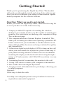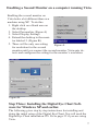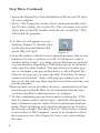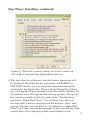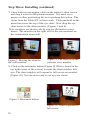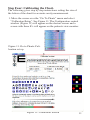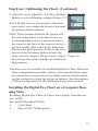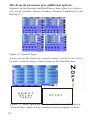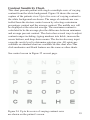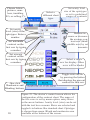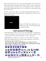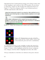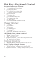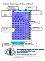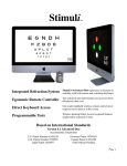
1
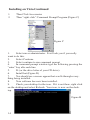
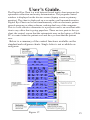
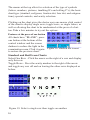
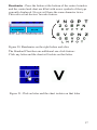
m
al E
h
it
ig
C
ye
D
Getting Started Manual
Installation and User Guide
Version 2
An affordable digital eye chart solution.
www.DigitalEyeChart.com
(208) 520 4292
[email protected]
art.co
art.co
h
m
ital E
ig
C
ye
D
© Copyright 2006-2007 DigitalEyeChart.com
All rights reserved
An affordable digital eye chart solution.
www.DigitalEyeChart.com
(208) 520 4292
[email protected]
Contents
Getting Started ‑—–
Step One: What you need to get started.
Step Two: Enabling the Wall Monitor.
Step Two: Enabling the Wall Monitor (continued).
Enabling a Second Monitor on Vista.
Step Three: Installing the Digital Eye
Chart Software for Windows XP and earlier.
Step Four: Calibrating the Chart.
Installing the Digital Eye Chart on Microsoft’s Vista
Installing on Vista Continued
4
4
5
6
7
7
11
13
14
User’s Guide.‑—–
15
Advanced Setup.‑—–
Trouble Shooting‑—–
23
25
Features at the press of one button
The drop-down menus give additional options.
Contrast Sensitivity Chart.
Single Letter Variable Acuity Chart.
No icon on the desktop
Start up screens do not appear
16
18
19
21
25
25
© Copyright 2006-2007 DigitalEyeChart.com
All rights reserved
Getting Started
Thank you for purchasing the Digital Eye Chart. This booklet
will guide you through the install and setup of the software and
show you how to configure your laptop or dual monitor capable
desktop computer for use with the software.
Step One: What you need to get started.
Before you install the Digital Eye Chart, check the following list
to see if you have all of the items necessary.
1. A laptop or tablet PC capable of extending the windows
desktop to an external monitor or a PC capable of running two
monitors. For instructions on checking your computer see Step
Two on the next page.
2. The computer must have Internet Explorer 6 installed. This
limits you to running on a Microsoft operating system like XP.
Please contact us if you would like to run the software on another platform. Other browsers are being evaluated for quality
and compatibility.
3. A flat screen liquid crystal display (LCD) to hang on the wall
where your front mirror for a projector system would hang. If
your patient viewing distance is under 9 feet we recommend
mounting the display on the back wall and viewing through a
mirror. A 17 inch monitor with 1280x1024 resolution is recommended.
4. A mounting bracket for mounting the monitor to the wall.
5. A long VGA cable to connect your computer to the monitor.
6. The install CD for the Digital Eye Chart.
7. A login account with administrative priviledges--allowing you
to install programs.
Optional:
Cable trays to hide the cable.
Visit http://www.digitaleyechart.com/system.htm for more on
required/recommended equipment.
Step Two: Enabling the Wall Monitor.
The Digital Eye Chart uses two monitors: one for the control
screen that the optometrist sees and one to display the acuity
chart to the patient. First you need to enable the external monitor.
If you are running Windows Vista operating system please see
page 23 for detail on how to set up the wall monitor.
1. Right click on an open area of Windows desk top. A menu will appear
(Figure 1). Left click on Properties
from the menu.
2. A dialog box will appear. Click on
the Settings tab at the top of the box
as in (Figure 2).
Note: if two rectangles are present the
computer’s graphics card supports
the external (second) monitor that the
Figure 1.
Digital Eye Cart requires.
Figure 2.
Step Two: Enabling the Wall Monitor (continued).
3. Click on the rectangle with a “2” in the center to select the
second monitor
4. Towards the bottom of the dialog there are two check boxes.
Check the box that says, “Extend my Windows desktop onto
this monitor.” (Figure 3.)
Figure 3.
5. Adjust the resolution of the display by moving the arrow
below the resolution section. The resolution needs to match the
resolution of the monitor on the wall. This information can be
found in the user’s manual for the monitor. If you are using the
recommended monitor, the resolution will be 1280x1024.
6. Click “Apply”
7. Now plug the wall monitor into the laptop using the long VGA
cable. You may want to do this on your desk prior to hanging
the monitor on the wall to verify the setup. See Figure 4.
Note: you will now be able to use both screens. Try moving the
cursor past the right edge of the main screen. You will see the
cursor on the wall monitor if steps were followed correctly.
The method of mounting your
monitor to the wall and running the cables is dependent
on your examination room
setup. A typical setup will use
an inexpensive wall bracket
mounted with dry wall or other
types of anchors. Cables may
Figure 4.
be routed outside or inside
walls depending on your needs.
Cable raceways such as those
at Blackbox.com can be used to
disguise exposed cabling.
Enabling a Second Monitor on a computer running Vista.
Enabling the second monitor on
Vista looks a bit different than on a
machine using XP. To do this:
1. Right click on a blank area on
the desktop
2. Select Personalize (Figure A)
. Select Display Settings
. Extend the desktop to the monitor labeled 2. (Figure B)
5. There will be only one setting
Figure A.
for resolution for the second
monitor until you connect the second monitor. Vista auto detects and configures the setting for the monitor’s resolution.
Figure B.
Step Three: Installing the Digital Eye Chart Soft‑
ware for Windows XP and earlier.
The following gives step by step instructions for installing and
doing the initial setup of the Digital Eye Chart. You will need the
Digital Eye Chart installation CD. Go to page 22 if you are using
Vista.
Step Three Continued
1. Insert the Digital Eye Chart Installation CD into the CD drive
of your computer.
2. Go to “My Computer” on the “Start” menu and double click
the CD drive (likely drive letter D:). This will open a list of all
of the files on the CD. Double click the file “install.bat”, This
will install the program.
3. A short cut will appear on your
desktop. (Figure 5). Double click
on the short cut and Internet Explorer (IE) will open.
Figure 5.
4. If an IE window with the license agreement opens skip to step
number 6. If only a window to a link “Click here if control
window did not start”, it is likely pop-up blockers are enabled
on your machine. Digital Eye Chart uses pop-ups to automatically open the chart window. You may choose to enable popups or configure your pop-up blocker(s) to allow Digital Eye
Chart to use pop-ups. Or, press the link “Click here if control
window did not start.” Note: with pop-ups enabled you will
have to do this and one other step discussed later each time you
run the program.
Many internet service providers, browsers, and internet tool bars
provide pop-up blocks. Refer to documentation for the ones
you have installed to determine how to configure.
5. If after configuring pop-up blocks and/or clicking the “Click
here if control window did not start,” check the Advanced settings of internet explorer. Select Tools from Internet Explorer
menu. Click on Options and select the advanced tab. Scroll to
the Security settings. The check box for “Allow active content
to run in files on My Computer” needs to be checked to allow
the program to run. (See Figure 6). Leave your other settings
the same.
Step Three: Installing (continued)
Figure 6. Check the security setting for active content on
file on My Computer. See highlighted selection.
6. The first time the software is run the license agreement will
be displayed. Read the license agreement and AGREE or
DECLINE. In the case you accept the agreement the initial
window for the Digital Eye Chart with the Digital Eye Chart
logo will appear. If pop-ups have been allowed the window for
the patients view will appear with scenery pictures. If pop-ups
have not been enabled click the menu item, “Troubleshoot,”
and select “Open Wall Chart.” You will now have the control and chart windows displayed on the monitor. Note: with
pop-ups blocked you will need to “Troubleshoot->Open Wall
Chart” each time you run the program. If this step did not work
consult http://www.digitaleyechart.com/faq.htm or call.
Step Three: Installing (continued)
7. Once both screens appear, click on the patient’s chart screen
and drag it across to the patient monitor. You must use a
mouse or other positioning device to perform this action. The
stylus from the Tablet PC will not work. Click and hold on the
menu bar across the top of the eye chart. Now drag the eye
chart across to the other monitor. (Figures 7 and 8).
Note: monitors are shown side by side for illustrative convenience. The monitor on the right will be the one mounted on
the examination room wall.
Figure 7. Moving the chart to
the wall monitor
Figure 8. The chart is on the
patients view monitor
8. Click on the maximize button (Figure 9) (This is found in the
top right corner of the screen) to make the chart window full
size. The chart window will expand to full screen on monitor.
(Figure 10). You are now ready to set up your charts.
Figure 9. Maximize button.
Figure 10. Chart expanded to
full screen.
10
Step Four: Calibrating the Chart.
The following gives step by step instructions setting the size of
the letters of the chart for accurate acuity measurement.
1. Move the cursor over the “Go To Charts” menu and select
“Calibration/Setup”. See Figure 11. The Configuration control
window (Figure 12) will appear on the doctors screen and a
screen with three E’s will appear on the patients view monitor.
Figure 11. Go to Charts-Calibration set up.
Figure 12. Calibration Screen
11
Step Four: Calibrating the Chart. (Continued)
2. Next, measure the distance from the patient to the wall monitor in inches.
3. Enter that number in the Calibration Assistant Chart distance
entry box and click Calculate. (Figure 13). The result is given
in three forms (inches decimal, inches fractional, and millimeters).
Figure 13. Calibration Assistant
4. Next, measure the top “E” on the wall chart. We will now
adjust it to match the calculated size.
5. If the E is larger than the calculation on the calibration screen
then click on the down arrows next to the E. The small arrow
will decrease the size of the E by single steps and the large arrow will increase the size in larger increments. If the E is too
small, then click on the up arrows. (Figure 14). Note: This is
the size the 20/100 letters will appear on the chart. The optometrist should verify the size meets their standard.
Measure this “E”
Figure 14.
12
Step Four: Calibrating the Chart. (Continued)
6. After the size is adjusted, click Save Settings
Button to save calibration settings (Figure 15).
You will only have to perform the calibration
once unless you change the distance between
Figure 15.
the patient and the monitor.
Note: If the distance between the patient and
the wall in the office is less than 9 feet, we
recommend that you use a mirror and place
the screen at the back of the room in order to
get best results. This is due to the finite resolution of the LCD monitor. If this is the case
then click on the mirror button to have the
chart mirrored. (Figure 16) for correct reflect- Figure 16.
ed viewing. You must click the save button to
keep changes.
You have now successfully set up the Digital Eye Chart. There are
other configurations possible, such as, selecting the letters, number, and pictures you prefer to use. Other options include adjusting the contrast level and the red/green balance. See descriptions
of these configurations in the Advanced Setup Tools section.
Installing the Digital Eye Chart on a Computer Run‑
ning Vista
Installing Digital Eye Chart on Vista varies slightly from the process on XP.
Put install CDin the CD drive
1.
Click Start:
2.
Then Click “All Programs”
13
Installing on Vista Continued
1.
2.
Then Click Accessories
Then “right click” Command Prompt Program (Figure C)
Figure C
1.
Select run as administrator. It will ask you if you really
want to do this.
2.
Select Continue.
.
Select continue to run command prompt
.
In command prompt window type the following pressing the
“enter” key afte each line:
5.
D: (or the drive letter of your CD drive)
6.
Install.bat (Figure D)
7.
You should see a screen appear that scrolls through everything being installed.
8.
Your software has now been installed.
9.
Check your desktop for the icon. If it is not there, right click
on the desktop and select Refresh. Your icon, is now on the desktop.
Figure B
14
User’s Guide.
The Digital Eye Chart is a web browser based acuity chart program for
optometric refraction and acuity determination. The program control
window is displayed on the doctors screen (laptop screen or primary
monitor). The chart is displayed on a secondary wall mounted monitor.
Digital Eye Chart can be run simultaneously with an electronic patient
records program or other software, making dual use of the computer.
This is a cost effective alternative to a projector and is an excellent addition to any office that is going paperless. There are two parts to the eye
chart, the control screen that the optometrist uses on the laptop or Tablet
PC to control what the patient sees and the eye chart that the patient
sees.
Below is a summary of the control functions available on the
standard and red/green charts. Single letter is not available on
red/green.
Figure 17.
15
The menus at the top allow for selection of the type of symbols
(letters, numbers, pictures, tumbling E’s and rolling C’s); the basic
chart type (standard, red/green, fixation dot, four dot, and astigmatism); special controls; and acuity selection.
Clicking on the chart gives the doctor easy one mouse click control
of the chart to display single rows, toggle rows, or single letters, as
well as allowing the chart to be randomized at the press of a button. Take a few minutes to try out the options.
Features at the press of one button
All charts have “BLANK”: press
one button at the bottom of the
control window and the screen
darkens to reduce the light in the
examination room. Click it again Figure 18. Darken the screen
to restore the previous chart.
Standard and Red/Green Charts:
Select One Row - Click the arrow on the right of a row and display
only this row.
Toggle Rows - Press the acuity number to the right of the arrow
and toggle any row off and on leaving the other rows displayed as
before.
Figure 19. Select a single row then toggle on another.
16
Randomize - Press the button at the bottom of the control window
and the control and chart are filled with a new symbols of the type
currently displayed. No row will have the same character twice.
This rates as our doctors’ favorite feature.
Figure 20. Randomize on the right before and after.
The Standard Chart has one additional one click feature:
Click any letter and the chart will isolate on that letter.
Figure 21. Click an letter and the chart isolates on that letter
17
The drop-down menus give additional options.
Symbols on the Standard and Red/Green charts allow for a choice
of 5 sets of symbols: Letters, Numbers, Pictures, Tumbling E’s and
Rolling C’s.
Figure 22. Symbol Types.
Acuity: allows the choice of a specific acuity, sets of 3 rows of acuity and a vertical (single column) chart on the standard chart.
Figure 23. Acuity menu and results available from it. Clockwise:
Vertical chart, single acuity, commonly used groupings of three.
18
Contrast Sensitivity Chart.
This chart presents patient with single or multiple rows of varying
contrast from the white background. Figure 24 shows the screen
capture of the patients view. Up to five rows of varying contrast to
the white background are shown. The range of contrasts are controlled from the doctors control screen by selecting a minimum
percentage contrast and the average contrast. The middle row will
be displayed at the selected average. The maximum contrast is
calculated to be the average plus the difference between minimum
and average percent contrast. The doctor has several ways to adjust
contrast ranges including: typing numbers into fields, increase/decrease buttons, and drop-down menus. The doctor also may input
a specific acuity level to determine optotype size. All optotypes
available on standard chart are available on this chart also. One
click randomize and blank features are the same as other charts.
See control screen in Figure 25 on next page.
Figure 24. Up to five rows of varying contrast rows
are shown on the patient’s screen.
19
Choose letters,
pictures, numbers, tumbling
E’s, or rolling C’s
Set acuity
level (size) of the
optotypes. Enter a
number.
Set minimum
contrast on the
first row by typing
a number
Set average
contrast on the
first row by typing
a number
One click
Randomize and
Blanking buttons.
20
Select a
different chart
type.
Set acuity level
size of the optotypes
or set to predefined
ranges of contrasts
Buttons increase or decrease
the average contrast row (third/
middle row) by set
amounts.
Select a single
row for display. Other
rows will be blanks
Toggle rows off/on
by pressing the button
that displays the percent
contrast for that row.
Figure 25. The doctor’s control screen allows for
configuration of the contrast chart. The range of
the five rows is set by menu option, entry boxes
or the arrow buttons. Acuity level (size) can be set
with the text box or menu. Rows are selected and
toggled via buttons like standard chart. Optotype
is chosen from menu. Blank and randomize area
available at the bottom of the screen.
Single Letter Variable Acuity Chart.
This chart allows you to present any of the optotypes in a one letter
chart. The acuity level of the chart is variable to any whole number.
This is an effective way to assess patients at greater than 20/400
when only one letter will fit on the screen at a time. The maximum
letter size depends on the examination room configuration and the
size of LCD monitor. This chart has the one click randomize and
blank, as well as arrows to click to double and halve the size. Selection of the optotypes is the same as the standard chart.
Choose Letters,
pictures, number, etc.
Type desired
acuity here
Double size of the
optotype.
Increase size of
optotype by 50%.
Decrease size of
to 75%
Halve the size
of the optotype.
Figure 26. The doctor’s control screen allows for
several ways to adjust the size of the optotype on
the patients’s view. The triangular buttons allow
for adjustment by factor of two or factor of 1.5
(small buttons). A whole number acuity can be
typed into the entry box. Of specific acuity level
can be picked from a drop down menu. Choose
type of symbol from menu
Figure 27. This single large optotype is
centered on the patient’s screen.
21
Type on all charts allows a different chart to be selected: Standard,
Red/Green, Fixation Dot, Four Dot, Astigmatism, Large variable
chart, contrast sensitivity, children’s animated fixation dot and a
slide show of educational, promotional or entertaining material.
Also click here to get back to setup screen.
Figure 28. Select the various chart types, slide show, or setup
screen from the Type menu.
22
The default slide show is a series of photographs from the Teton/
Yellowstone National Parks area. These slides can be customized
with educational, promotional or entertainment slide. Contact us
for custom slide generation service or details on creating and linking in your own.
Control: allows the chart to be masked making the background
dark except for the selected letter(s). It also allows all rows to be
enabled or cleared.
Figure 29. Mask the isolated rows or
symbol. Provides a dark background
around the letters.
Advanced Setup.
The Digital Eye Chart provides several additional configuration
options. Symbols to be used can be selected. The contrast can be
controlled and the red/green balance can be adjusted.
Highlight the symbols you want to use in the chart. Clicking
them will toggle between selected (surrounded by a blue box)
and deselected (no blue box).
Figure 30. Select symbols to use in the Calibration/Setup screen.
23
Optometrists have found patients testing out to better acuities due
to the brightness and contrast of the LCD monitor. If you desire
to adjust the contrast use the background adjustment shown in
Figure 31. Tune the red/green chart to your red/green glasses
with the adjustment on the bottom.
Figure 31. Adjust the background contrast and red/green balance.
Figure 32. Optometrists can also select the
type of four-dot test. Select either circles only
or the diamond, plus and circle combination.
A configuration choice is also available to allow the choice between circles or a combination of shapes for the four-dot chart.
Figure 32 shows a blue highlight around the chosen configuration. Simply click the other to highlight and chose the other.
Always remember to click the save button to keep new choices.
24
Trouble Shooting
No icon on the desktop
1.
Go to my computer. Click on the C drive button or the drive
that is your hard drive.
2.
Double click on Program Files
3.
Double click on DEC-Install. Look for the file DigitalEyeChart.
There is no file extension.
4.
If the file is there, drag it to the desktop.
If the file is not there, please contact Heidi at [email protected] or (208)520-4292 and tell her you are missing the
DigitalEyeChart shortcut file and she will send you a new disk ASAP.
5.
If you are using Vista, right click the desktop and Refresh your
screen. You should now see your icon.
Start up screens do not appear
1.
Check that all pop-up blockers are turned off. You might have
to check in several locations and for several different programs. Internet Explore has pop up blockers, Norton does, Google does. To see
if this is a problem, look down at the bottom the the browser and look
or any warning messages there. You can also look at the top of the
browser and sometimes there are messages that say something to the
effect that a window has been blocked. If you see any of these then:
a.
On Internet Explorer click on the tools button.
b.
Select Pop-Up Blocker and choose turn off Pop-up
blocker on this site only.
c. Click on the link on the one start up page that did appear.
d.
Repeat this procedure for each of the programs that you
have installed that have pop-up blockers.
2.
Once all of the pop-up blockers have been turned off, if the
screens still do not appear check to see if active content is allowed to
run. To do this:
a.
Go to Tools on the menu bar
b.
Go to Internet Options
c.
Click on the advanced tab
d,
Select “Allow active content to run in files on My
Computer”
e.
Click OK
25
Hot Key--Keyboard Control
Switch Between Charts
•
•
•
•
•
•
•
•
•
•
“s” standard multi-line chart
“r” red/green chart
“v” variable low vision chart
“t” contrast sensitivity chart
“d” four dot test
“f” fixation dot
“g” animatd fixation dot
“a” astigmatism chart
“w” slide show
“b” blank/unblank (darken screen)
•
•
•
•
•
•
“l” letters
“n” numbers
“p” pictures
“e” tumbling E’s
“c” rolling C’s
“space bar” randomize current type
•
•
•
•
“Home” show all rows
“End” clear all rows
Up/Down Arrows -- move to next/previous row
“m” mask selected items
•
“PgUp/PgDown” change mean row by 5% +/-
•
•
“PgUp/PgDown” change acuity double/half
Up/Down Arrows -- change acuity level by 10%
Change Optotype
All Multi-line chart control
Contrast Sensitivity
Low Vision Single Letter
26
Chart Function Cheat Sheet
Chart Type:
Control:
Select Red/Green,
Fixation, Fourdot, etc.
Show all, Blank all, and
darken background
Select Acuity
:
Choose Symbol Type:
Use menu to select an
acuity or a set of 3 acuity
rows to display
Letters
Numbers
Symbols
Rolling E's
Rolling C's
Toggle Row:
Turn a row off and on.
One Row Only:
Single Letter:
Display this row only
Click on any letter to show only
one letter.
One Click Blank:
Randomize:
Darken the chart to reduce
illumination in the exam room.
Return to chart by clicking again.
m
al E
h
it
ig
An affordable digital eye chart solution.
www.DigitalEyeChart.com
(208) 520 4292
[email protected]
C
ye
D
Randomize the chart
with one click.
© Copyright 2006-2007 DigitalEyeChart.com
All rights reserved
27
art.co
Please contact us at [email protected] with your feed
back on the chart or this installation and user’s guide.
Refer to our webpage for frequently asked questions.
http://www.digitaleyechart.com/faq.htm
Call 208 520 4292
or contact in writing at:
m
al E
art.co
28
h
it
ig
An affordable digital eye chart solution.
www.DigitalEyeChart.com
(208) 520 4292
[email protected]
C
ye
D
Digital Eye Chart
3103 Sandstone Drive
Idaho Falls, Idaho 83404
© Copyright 2006-2007 DigitalEyeChart.com
All rights reserved