1
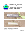
DRAFT
Protocols for Measuring
Continuous Water
Temperature Using an
Onset Data Logger
Tom Danielson, Maine Department of Environmental Protection
17 State House Station, Augusta, ME, 04333
(207) 287-7728
[email protected]
December 2004
DEPLW0639
DRAFT
Standard Operating Procedure
Bureau of Land and Water Quality
Date: 06/05/05
Doc num: DEPLW0639
Bureau of Land and Water Quality
Division of Environmental Assessment
Biomonitoring Program
Standard Operating Procedure
DRAFT Protocols for Measuring Continuous Water Temperature
Using an Onset Data Logger
1.
Applicability. This standard operating procedure (SOP) applies to the collection and
analysis of continuous water temperature data from wadeable rivers and streams in Maine
using an Onset Data Logger; either an Optic Stowaway Temperature Logger or a HOBO
Water Temp Pro logger.
2.
Purpose. The purpose of this SOP is to provide standardized methods for collecting and
processing continuous water temperature data from wadeable rivers and streams in Maine.
3.
Definition. Continuous water temperature data are those that are collected at certain time
intervals (e.g., every 10 or 30 minutes) for an extended period of time (e.g., 4-6 weeks)
using an electronic temperature logger deployed in a river or stream.
4.
Responsibilities
A.
Training. It is the responsibility of the task manager for whose project temperature
data are collected to ensure that the individual(s) using the loggers are familiar with
this SOP.
B.
Tracking of temperature logger usage. It is the responsibility of the individual
launching, deploying, or retrieving a logger to note these activities on the relevant
tracking forms and/or field sheet; this is especially important if a logger is to be
deployed and retrieved by different groups (i.e., algae versus macroinvertebrate staff).
It is the responsibility of the task manager to place completed tracking forms in the
appropriate folder located in the Biomonitoring staff area.
C.
Data retrieval and processing. It is the responsibility of the task manager or the staff
member retrieving/processing the data to note these activities on the relevant tracking
forms. When all data have been processed, these forms will be printed out and
included in the Biomonitoring unit’s QAPP folder.
Methods for Using
Onset Temperature Loggers
Page 2 of 7
Division of Environmental Assessment
Biological Monitoring Program
DRAFT
5.
Standard Operating Procedure
Bureau of Land and Water Quality
Date: 06/05/05
Doc num: DEPLW0639
Guidelines and Procedures
A.
Measurement period. In the majority of cases, temperature data will be collected
concurrently with the sampling of algae and/or macroinvertebrates during the summer
low flow period.
B.
Materials
(1) Launched temperature logger, labeled with deployment location.
(2) Cable ties, nylon rope, steel cable, and rebar where appropriate, to anchor
logger in deployment location.
(3) Lengths of PVC pipe (~6 inches) to shade logger. PVC pipe has 2 holes drilled
at one end to allow it to be secured to the logger with cable ties.
(4) Appropriate field data sheet to note deployment/retrieval of logger.
(5) Color-coded flagging tape to mark logger location.
C.
Precautions and limitations
(1) The Optic Stowaway Temperature Logger is only suitable for measurements in
the range of 23°F to 99°F (-5°C to +37°C).
(2) The HOBO Water Temp Pro is only suitable for measurements in the range of
32°F to 122°F (0°C to 50°C).
D.
Procedures
(1) Pre-deployment logger calibration. Prior to each sampling season, all
temperature loggers should be calibrated according to the procedures outlined in
the Protocols for Calibrating Onset Temperature Loggers (App. 1).
(2) Pre-deployment logger launch
(a) Optic Stowaway Temp Logger
i.
Connect the Optic Base Station to a host computer that has the
BoxCar software installed using the appropriate interface cable.
Slide the Optic Stowaway Temperature Logger into the Optic
Coupler on the Optic Base Station.
ii. Start the BoxCar software program and go to Logger > Launch.
Update the description (i.e., planned deployment location), the
interval (i.e., 10 minutes), and measuring units (i.e., degrees
Celsius). Make sure ‘Wrap Around When Full’ is not selected; this
function will overwrite existing data when logger becomes full.
iii. Enter logger type and number, launch date and time, name of MDEP
staff who launched logger, measurement interval, and planned
deployment location in the logger tracking file
[H:L&W/WATERSHED/Monitoring & Assessment/Program/
Biomonitoring/SOP-QAPP/Temp logger tracking] (App. 2). Using
tape, label temperature logger with planned deployment location.
Methods for Using
Onset Temperature Loggers
Page 3 of 7
Division of Environmental Assessment
Biological Monitoring Program
DRAFT
Standard Operating Procedure
Bureau of Land and Water Quality
Date: 06/05/05
Doc num: DEPLW0639
(b)
(3)
(4)
HOBO Water Temp Pro
i.
Connect IR Base station to a host computer that has the BoxCar
software installed using the appropriate interface cable and align
communication window on base station with communication
window on logger.
ii. Open BoxCar software program and go to Logger > HOBO Water
Temp Pro > Launch. Update the description (i.e., planned
deployment location) and measurements units (degrees Celsius).
Make sure stealth mode is NOT selected. Select ‘Launch
Immediately’ and logger should begin recording data, LED will
blink every 5 seconds during logging.
iii. Enter information as in (2) (a) iii, above, in the logger tracking file
(App. 2). Using tape, label temperature logger with planned
deployment location.
Logger deployment
(a) Determine a suitable site for deployment in line with the program’s
objectives.
(b) Attach logger (with the sensor end down) with a cable tie, nylon rope, or
steel cable to a suitable deployment point, for example:
i.
a sturdy structure such as a large tree root;
ii. a rebar stake driven into the stream bed;
iii. one of the sampling devices (e.g., rock bag). This is the preferred
method if the site is being sampled for macroinvertebrates.
If options i. – iii. are not applicable, the task manager should use
his/her best judgment to find a suitable attachment point.
(c) If the deployment location is in a sunny area, the logger should be secured
within a length of PVC pipe or shaded in some other way.
(d) The Hobo Water Temp Pro loggers tend to float and steps should be taken
to ensure the logger remains completely submerged throughout the
sampling period. For example, the logger could be placed under a boulder
or within a length of PVC pipe with both ends secured so one end doesn’t
float.
(e) To aid in logger retrieval, flag or mark the area of deployment with colorcoded flagging tape, make a drawing on the field sheet indicating logger
location, and note location (e.g., attached to rock bag). It may also be
beneficial to record GPS coordinates of the location, if available.
(f) Check box ‘Temperature Probe deployed’ on the field sheet and note
logger number. Make sure to note if logger was deployed in a different
location than planned. When back at the MDEP office, enter deployment
information in the temperature logger tracking file (App. 2).
Logger retrieval
(a) Locate the logger utilizing flagging, marking, drawing, notes or GPS
coordinates as necessary. Retrieve logger and check box ‘Temperature
Methods for Using
Onset Temperature Loggers
Page 4 of 7
Division of Environmental Assessment
Biological Monitoring Program
DRAFT
(5)
(6)
Standard Operating Procedure
Bureau of Land and Water Quality
Date: 06/05/05
Doc num: DEPLW0639
Probe retrieved’ on the field sheet. When back at the MDEP office, enter
retrieval information in the logger tracking file (App. 2).
(b) Keep logger in a safe location and return it to the MDEP office for data
retrieval and processing.
Data retrieval
(a) Optic Stowaway Temp Logger
i.
Connect the Optic Base Station to a host computer that has the
BoxCar software installed using the appropriate interface cable.
Slide the Optic Stowaway Temperature Logger into the Optic
Coupler on the Optic Base Station.
ii. Start the BoxCar software program and go to Logger > Readout.
iii. Select location to save data [H:L&W/WATERSHED/Monitoring &
Assessment/Program/Biomonitoring/STREAM DATA/H2OTEMPS/
(appropriate year)/dtf files/] and rename file as appropriate (e.g.,
Pretty_Brook_Sxxx_PrettyTown.dtf; if station number has not yet
been assigned, add descriptor, e.g., upstream, below POTW). Select
‘Temperature ˚C’ and click OK. This will create a graph of all data
records collected.
iv. Enter retrieval information in temperature logger tracking file (App.
2).
(b) HOBO Water Temp Pro
i.
Connect IR Base station to a host computer that has the BoxCar
software installed using the appropriate interface cable.
ii. Open BoxCar software program and go to Logger > HOBO Water
Temp Pro > Readout.
iii. Select desired logger and select ‘Stop logging and off load data.’
iv. Select location to save data and rename file as appropriate [see (5)
(a) iii, above]. This will create a graph of all data records collected.
v.
Enter retrieval information in temperature logger tracking file (App.
2).
Data processing
(a) Export data into a text file:
i.
With desired BoxCar Pro graph (dtf. file type) open, go to File >
Export > Custom > Preferences. Set the Date Style to: ‘Month and
Day (Include Year)’, the Date Time Separator to: ‘Space ()’, the
Time Style to: ‘Hr. Min.’ and the Data Separator to: ‘Comma (,)’,
click OK.
ii. Click on Export and select location to save text file [H:L&W/
WATERSHED/ Monitoring & Assessment/Program/
Biomonitoring/STREAM DATA/ H2OTEMPS/(appropriate
year)/text files/] and rename as appropriate [see (5) (a) iii, above, but
use file extension ‘txt’).
iii. Enter processing information in temperature logger tracking file
(App. 2).
Methods for Using
Onset Temperature Loggers
Page 5 of 7
Division of Environmental Assessment
Biological Monitoring Program
DRAFT
(b)
(c)
Standard Operating Procedure
Bureau of Land and Water Quality
Date: 06/05/05
Doc num: DEPLW0639
Convert text file to an Excel file:
i.
In Excel, open desired text file from location noted in (6) (a) ii,
above.
ii. Select ‘Delimited’ data file type and click Next. Select ‘Tab’ and
‘Comma’ as Delimiters. Click Finish.
iii. Save file as a Microsoft Excel Workbook in desired location
[H:L&W/WATERSHED/Monitoring & Assessment/Program/
Biomonitoring/STREAM DATA/ H2OTEMPS/ (appropriate
year)/Excel files/] and rename as appropriate [see (5) (a) iii, above,
but use file extension ‘xls’).
iv. Enter processing information in temperature logger tracking file
(App. 2).
Creating Excel charts for the SWAT report
i.
Open desired Excel file from location noted in (6) (b) iii, above.
Delete all data recorded up until 1 h before deployment, and data
recorded >1 h after retrieval. For example, for a logger deployed at
approximately 2 p.m. and retrieved at approximately 11 a.m., all data
collected before 1 p.m. on the deployment date and after 12 p.m. on
the retrieval date should be deleted.
ii. For graphing purpose, only a subset of the retained data will be used,
that is all data recorded between midnight of the day after the
deployment day and midnight of the retrieval day. For example, for
a logger deployed on July 7th and retrieved on August 9th, only data
collected between midnight on July 7th/8th and midnight on August
8th/9th will be graphed.
iii. Select the data outlined in (6) (c) ii, above, and using the Chart
Wizard function, create an XY (Scatter) chart (using Chart sub-type
‘Scatter with data points connected by lines without markers’).
Click ‘Next’ twice. Title the chart: ‘Stream Name, Town [station
number – relevant identifier (if any)], in Arial size 12. In same
window, click on ‘Legend’ tab and remove check mark next to
‘Show Legend’. Click ‘Finish’.
iv. Resize the chart to 9 cells wide and 20 cell tall.
v.
Format the Y-axis so that on the Scale Tab, the maximum scale
equals 35.
vi. Format the X-axis so that on the Scale Tab, the major unit equals 7
(or 14 if dates do not plot well at 7) and on the Number Tab the
Date format is ‘03/04/97’.
vii. Calculate the minimum, maximum, and average temperature for the
data set as well as the spread.
viii. Create a text box, with Arial font size 10. Place it within the chart
area and include the following summary information for the data set:
the maximum temperature (‘max = …’), the minimum temperature
(‘min = …’), the average temperature (‘average = …), and the
Methods for Using
Onset Temperature Loggers
Page 6 of 7
Division of Environmental Assessment
Biological Monitoring Program
DRAFT
(d)
6.
Standard Operating Procedure
Bureau of Land and Water Quality
Date: 06/05/05
Doc num: DEPLW0639
spread of all data points (‘max - min = …), with this statement:
‘Summary statistics in degrees Celsius’ at the top of the box.
ix. Save the file to the existing location, see (6) (b) iii, above, with the
existing file name.
Transfer Excel graph into a Word document
i.
Open desired Excel file from the location noted in (6) (b) iii, above,
select the chart and copy it.
ii. Open a new Word document. From the Edit Menu, click Paste
Special. In the ‘As’ box, select ‘Picture (Enhanced Metafile)’, and
click OK.
iii. Right click on the chart and ‘Format picture …’ so that on the Size
tab, the height is set to 2.11” and the width is set to 3.55”. Remove
activation check mark next to ‘Lock aspect ratio’ and click OK.
iv. Position the picture so that eight pictures (Excel charts) will fit on
each Word document page. Align charts relative to each other, and
ensure that all the charts are equidistant from the page margin and
each other.
v.
Select location to save Word file [H:L&W/WATERSHED/
Monitoring & Assessment/Program/Biomonitoring/Documents/
SWAT Reports/(appropriate year)_SWAT Report] and rename file
as: appropriate year_TempGraphs.doc.
Care and Maintenance
A.
After use, clean the logger using only non-abrasive mild soap and warm water with a
non-scratching sponge or cloth. Any scratches on the logger’s surface may impair
communication. If necessary a plastic polish may be used for tougher cleaning jobs.
B.
Be sure to keep the logger free from dirt and dust when not in use.
7.
QA/QC Procedures. At the start of each sampling season, all temperature loggers will be
calibrated using the procedure outlined in the Protocols for Calibrating Onset Temperature
Loggers (App. 1).
8.
References
BoxCar Pro User's Manual, Onset Computer Corporation, Bourne, MA; HOBO Water
Temp Pro User’s Manual, Onset Computer Corporation, Bourne, MA; Optic Stowaway
Temp User’s Manual, Onset Computer Corporation, Bourne, MA.
Methods for Using
Onset Temperature Loggers
Page 7 of 7
Division of Environmental Assessment
Biological Monitoring Program