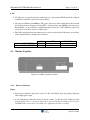
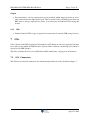
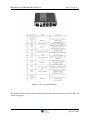
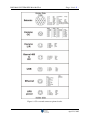
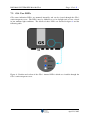
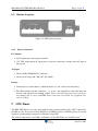
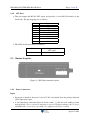
1
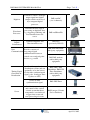
IMS-MAN-SYSTEM-HW-201410-GGv4
- Page 1 of 45 -
IMS System Hardware Users Guide
April 21, 2015
Document Number:
IMS-MAN-SYSTEM-HW-201410-GGv4
April 21, 2015
IMS-MAN-SYSTEM-HW-201410-GGv4
- Page 2 of 45 -
Contents
1
Introduction
6
2
IMS Hardware Components
6
3
Sensors
8
4
netADC
8
4.1
Front faceplate . . . . . . . . . . . . . . . . . . . . . . . . . . . . . . . . . .
8
4.1.1
User LEDS . . . . . . . . . . . . . . . . . . . . . . . . . . . . . . . .
9
4.1.2
User Buttons . . . . . . . . . . . . . . . . . . . . . . . . . . . . . . .
10
4.1.3
Data Ports . . . . . . . . . . . . . . . . . . . . . . . . . . . . . . . . .
10
Bottom faceplate . . . . . . . . . . . . . . . . . . . . . . . . . . . . . . . . .
11
4.2.1
Power Connectors . . . . . . . . . . . . . . . . . . . . . . . . . . . .
11
4.2.2
Seismic Connectors . . . . . . . . . . . . . . . . . . . . . . . . . . . .
12
4.2
5
preAMP
13
5.1
Front faceplate . . . . . . . . . . . . . . . . . . . . . . . . . . . . . . . . . .
13
5.1.1
User LEDS . . . . . . . . . . . . . . . . . . . . . . . . . . . . . . . .
13
5.1.2
Data Ports . . . . . . . . . . . . . . . . . . . . . . . . . . . . . . . . .
14
Bottom faceplate . . . . . . . . . . . . . . . . . . . . . . . . . . . . . . . . .
15
5.2.1
Power Connectors . . . . . . . . . . . . . . . . . . . . . . . . . . . .
15
5.2.2
Seismic Connectors . . . . . . . . . . . . . . . . . . . . . . . . . . . .
15
5.2
6
netSP(+)
16
6.1
Front faceplate . . . . . . . . . . . . . . . . . . . . . . . . . . . . . . . . . .
16
6.1.1
User LEDS . . . . . . . . . . . . . . . . . . . . . . . . . . . . . . . .
17
6.1.2
User Buttons . . . . . . . . . . . . . . . . . . . . . . . . . . . . . . .
19
6.1.3
Data Ports . . . . . . . . . . . . . . . . . . . . . . . . . . . . . . . . .
19
Bottom faceplate . . . . . . . . . . . . . . . . . . . . . . . . . . . . . . . . .
21
6.2.1
Power Connectors . . . . . . . . . . . . . . . . . . . . . . . . . . . .
21
6.2.2
USB . . . . . . . . . . . . . . . . . . . . . . . . . . . . . . . . . . . .
22
6.2
7
GS+
22
7.1
GS+ Connectors . . . . . . . . . . . . . . . . . . . . . . . . . . . . . . . . . .
22
7.2
GS+ User LED’s . . . . . . . . . . . . . . . . . . . . . . . . . . . . . . . . .
25
April 21, 2015
IMS-MAN-SYSTEM-HW-201410-GGv4
8
UPS
8.1
8.2
9
- Page 3 of 45 -
26
Front faceplate . . . . . . . . . . . . . . . . . . . . . . . . . . . . . . . . . .
26
8.1.1
User LEDS . . . . . . . . . . . . . . . . . . . . . . . . . . . . . . . .
27
Bottom faceplate . . . . . . . . . . . . . . . . . . . . . . . . . . . . . . . . .
28
8.2.1
28
Power Connectors . . . . . . . . . . . . . . . . . . . . . . . . . . . .
GPS-Timer
28
9.1
Front faceplate . . . . . . . . . . . . . . . . . . . . . . . . . . . . . . . . . .
29
9.1.1
User LEDS . . . . . . . . . . . . . . . . . . . . . . . . . . . . . . . .
29
9.1.2
User Buttons . . . . . . . . . . . . . . . . . . . . . . . . . . . . . . .
30
9.1.3
NMEA Port . . . . . . . . . . . . . . . . . . . . . . . . . . . . . . . .
30
9.1.4
ATU Port . . . . . . . . . . . . . . . . . . . . . . . . . . . . . . . . .
31
Bottom faceplate . . . . . . . . . . . . . . . . . . . . . . . . . . . . . . . . .
31
9.2.1
Power Connectors . . . . . . . . . . . . . . . . . . . . . . . . . . . .
31
9.2.2
GPS Antenna . . . . . . . . . . . . . . . . . . . . . . . . . . . . . . .
32
ATU Period . . . . . . . . . . . . . . . . . . . . . . . . . . . . . . . . . . . .
32
9.2
9.3
10 Time Distributor
33
10.1 Front Faceplate . . . . . . . . . . . . . . . . . . . . . . . . . . . . . . . . . .
33
10.1.1 Power Connector . . . . . . . . . . . . . . . . . . . . . . . . . . . . .
33
10.1.2 GPS Related Connectors . . . . . . . . . . . . . . . . . . . . . . . . .
33
10.1.3 User LEDs . . . . . . . . . . . . . . . . . . . . . . . . . . . . . . . .
34
10.1.4 User DIP Switches . . . . . . . . . . . . . . . . . . . . . . . . . . . .
35
10.1.5 I/O Ports . . . . . . . . . . . . . . . . . . . . . . . . . . . . . . . . .
35
11 PTP Time Distributor
36
11.1 Front Faceplate . . . . . . . . . . . . . . . . . . . . . . . . . . . . . . . . . .
36
11.1.1 Power Connector . . . . . . . . . . . . . . . . . . . . . . . . . . . . .
36
11.1.2 GPS Antenna Connector . . . . . . . . . . . . . . . . . . . . . . . . .
37
11.1.3 I/O Ports . . . . . . . . . . . . . . . . . . . . . . . . . . . . . . . . .
37
11.1.4 User LEDs . . . . . . . . . . . . . . . . . . . . . . . . . . . . . . . .
38
11.1.5 User DIP Switches . . . . . . . . . . . . . . . . . . . . . . . . . . . .
39
12 DSLAM and DSL modem
40
13 Synapse
40
April 21, 2015
IMS-MAN-SYSTEM-HW-201410-GGv4
- Page 4 of 45 -
A Logging into a netSP(+)
41
B Configuring a netSP(+)’s network settings
42
C Logging into a PTP Time Distributor
42
D Configuring a PTP Time Distributor’s network settings
43
April 21, 2015
IMS-MAN-SYSTEM-HW-201410-GGv4
- Page 5 of 45 -
List of Figures
1
netADC front faceplate. . . . . . . . . . . . . . . . . . . . . . . . . . . . . . .
9
2
netADC bottom faceplate. . . . . . . . . . . . . . . . . . . . . . . . . . . . .
11
3
preAMP front faceplate. . . . . . . . . . . . . . . . . . . . . . . . . . . . . .
13
4
preAMP bottom faceplate. . . . . . . . . . . . . . . . . . . . . . . . . . . . .
15
5
netSP front faceplate. . . . . . . . . . . . . . . . . . . . . . . . . . . . . . . .
17
6
netSP(+) bottom faceplate. . . . . . . . . . . . . . . . . . . . . . . . . . . . .
21
7
GS+ external connectors. . . . . . . . . . . . . . . . . . . . . . . . . . . . . .
23
8
GS+ external connector pinout details. . . . . . . . . . . . . . . . . . . . . . .
24
9
Position and colour of the GS+’s internal LED’s which are viewable through
the GS+’s semi-transparent cover. . . . . . . . . . . . . . . . . . . . . . . . .
25
10
UPS front faceplate. . . . . . . . . . . . . . . . . . . . . . . . . . . . . . . . .
26
11
UPS bottom faceplate. . . . . . . . . . . . . . . . . . . . . . . . . . . . . . .
28
12
GPS-Timer front faceplate. . . . . . . . . . . . . . . . . . . . . . . . . . . . .
29
13
GPS-Timer bottom faceplate. . . . . . . . . . . . . . . . . . . . . . . . . . . .
31
14
Time Distributor front faceplate. . . . . . . . . . . . . . . . . . . . . . . . . .
33
15
PTP Time Distributor front faceplate - showing master option with GPS antenna
connector. . . . . . . . . . . . . . . . . . . . . . . . . . . . . . . . . . . . . .
36
List of Tables
1
Basic Seismic System Components. . . . . . . . . . . . . . . . . . . . . . . .
6
3
Change record . . . . . . . . . . . . . . . . . . . . . . . . . . . . . . . . . . .
45
April 21, 2015
IMS-MAN-SYSTEM-HW-201410-GGv4
1
- Page 6 of 45 -
Introduction
This guide provides an overview of the hardware components used in a typical IMS microseismic monitoring system. The basic concepts required for understanding each device’s role
in the system as well as how the system components interact are introduced. Reference information such as connector pin mappings and important specifications is also provided.
A typical IMS system consists of a number of hardware components or modules, mostly manufactured by IMS. Depending on the specific application and system configuration (especially
relating to the system communications infrastructure), a number of third-party enabling components will be required, e.g. network switches, media converters, WiFi radios, etc. Most of
these components are commercially available, off-the-shelf products, and are usually provided
and administered by the customer or on-site IT department. Such devices are not covered in this
document.
This document assumes that the infrastructure required for the operation of a reliable TCP/IP
network, to which the IMS system has (preferably exclusive) access, exists and is fully operational.
2
IMS Hardware Components
A basic seismic monitoring system consists of seismic sensors, digitizers, (optional) waveform processors, communications hardware (including data and timing signal distribution) and
a server. Table 1 divides the basic monitoring system into a number of different categories. A
brief description of each category is given, and an example of some applicable IMS hardware
is listed.
Table 1: Basic Seismic System Components.
Sensor
Converts physical ground
motion to an analogue,
electrical signal.
IMS Geophone or
Accelerometer,
tri-axial or uni-axial in
various packages (e.g.
borehole, surface
mount, etc.)
Preamplifier
Amplifies analogue electrical
signals
IMS preAMP
April 21, 2015
IMS-MAN-SYSTEM-HW-201410-GGv4
- Page 7 of 45 -
Digitizer
Converts a sensor’s analogue
output signal into digital
samples which can be used
by a computer/digital
processor.
IMS netADC
(4 or 8 channels)
Waveform
Processor
Performs the first stage of
processing on digitized data,
e.g. triggering, buffering and
data transmission to the
server.
IMS netSP/netSP+
Integrated
Digital
Seismometer
Combined Digitizer and
Waveform Processor
IMS GS+
(previously ISS GS)
Data
Provides a means of
Communication long-range digital
communication between
central server and end-point
devices, e.g. netSP.
Timing Signal
Generation &
Distribution
Server
IMS DSLAM and/or
third party equipment.
IMS DSL modem
and/or third party
equipment.
Provides a path and
distribution system (and can
optionally act as the source)
for the time synchronisation
signal (a.k.a. Analogue Time
Update, or ATU).
IMS (GPS) Time
Distributor, IMS PTP
Time Distributor,
and/or third party
equipment.
Source of time
synchronisation signal.
IMS GPS-Timer
Coordination, monitoring
and control of the various
seismic system hardware
components, association of
triggers into events and
auto-processing of events.
IMS Synapse (Seismic
Server Software)
April 21, 2015
IMS-MAN-SYSTEM-HW-201410-GGv4
3
- Page 8 of 45 -
Sensors
IMS manufactures a number of different types of sensors (e.g. geophones, accelerometers,
FBA’s, etc.), in a number of different packaging styles (e.g. borehole sonde, surface mount, removable borehole sonde, etc.). All sensors contain internal “Smart Electronics”, which provide
such information as sensor orientation and identification data. IMS netADC’s are able to read
this information, and feed it into the system to assist with configuration (see section 4).
All sensors use a common wiring colour coding scheme as documented in the following table
for a three component sensor:
Sensor component
x
y
z
Smart Electronics
+ve
red
yellow
white
brown
-ve
blue
green
black
violet
Note: single component sensors use the same cable, but only connect to the “z” and “Smart
Electronics” pairs.
4
netADC
The netADC’s primary function is to digitize sensor signals measured on its analogue inputs,
and to send the digitized data to a waveform processor or seismic server node.
When the netADC powers up, it first scans its Smart Sensor inputs to see whether any IMS
Smart Sensors are detected. Once this has completed (about 30 seconds after power up), the
netADC uses the IMS WoE protocol to discover any IMS nodes on the Ethernet network that
are available to accept digitized data from the netADC; this is called “Discovery” mode. The
netADC reports any Smart Sensors it has detected during the scan, so that nodes have information about how many active sensor channels the netADC will digitize, and send in data for.
Typical nodes which are able to accept digitized data from a netADC are a netSP, netSP+ or
Synapse (seismic server software). Nodes will answer if they have sufficient spare capacity to
accept data from this netADC (they may already be processing another netADC’s data, and so
may not have spare capacity to process this netADC’s data). Once a node has been selected, the
netADC is said to have “Paired” with the node, and the netADC will configure itself based on
information received from the node (e.g. sampling rate, sensor/triggering settings, etc.).
The various connectors, user LED’s and buttons of the netADC are detailed below.
4.1
Front faceplate
April 21, 2015
IMS-MAN-SYSTEM-HW-201410-GGv4
- Page 9 of 45 -
Figure 1: netADC front faceplate.
4.1.1
User LEDS
Power
Solid Green
Flashes
Orange/Green
Internal electronics are
powered
netADC low level firmware
configuration (first few
seconds after power up)
Pair Status
Off
Blink Red
Blink Amber
Blink Green
Solid Green
netADC low level firmware
not configured
netADC initialising (reading
Smart Sensors, etc.)
“Discover” mode (looking
for netSP’s on network)
Initiated “pair” sequence
with netSP
Successfully “paired”
Sampling
Off
Blink Amber
Blink Green
Not sampling
Configuring ADC modules
Sampling data from analogue
sensor interface
April 21, 2015
IMS-MAN-SYSTEM-HW-201410-GGv4
- Page 10 of 45 -
ATU
Off
Solid Green
ATU has not been received
since last reset
ATU has not been received in
last two ATU periods
ATU OK
Blink Red
Blink Green
WoE message received
WoE message transmitted
Solid Red
WoE Tx/Rx
4.1.2
User Buttons
Reset
• The reset button resets all the internal electronics of the netADC immediately.
Test
• The test button is used for various factory tests.
4.1.3
Data Ports
LAN
• One Ethernet (10/100Base-TX) port is provided for connecting the netADC to the local
area network. This port has auto-MDIX (auto-crossover) functionality, so any standard,
straight-through or crossover, Ethernet patch lead can be used to connect to the network.
• The LEDs integrated into the connector are used to represent the link status and activity
on the medium and are interpreted as follows:
Amber (LINK SPEED)
Green (LINK/ACTIVITY)
ON
100 Mb/s
Link Up
OFF
10 Mb/s or None
No Link
TOGGLE
Activity (Tx or Rx)
Note: When digitized data is continuously streaming from the netADC, there is so much data
on the LAN port that the Green LED remains permanently in the off state (i.e. toggled “Link
Up” state).
April 21, 2015
IMS-MAN-SYSTEM-HW-201410-GGv4
- Page 11 of 45 -
ATU
• 3 wire RS-232 for input of time synchronization signal. Pin-outs of this table are as
follows:
Pin no.
1
2
3
4
5
6
7
8
4.2
Signal
RxD
GND
N/C
N/C
N/C
N/C
N/C
N/C
Bottom faceplate
Figure 2: netADC bottom faceplate.
4.2.1
Power Connectors
Input
• Input power should be between 12 and 15 V DC and should obey the polarity indicated
on the input power port.
• A low impedance connection between chassis earth ( ) and the local earthing system
must be made. This is extremely important to prevent equipment damage due to surges
and EMI. If this connection is not made, the equipment warranty is voided.
April 21, 2015
IMS-MAN-SYSTEM-HW-201410-GGv4
- Page 12 of 45 -
Output
• For convenience, a 2-way output power port is provided, which simply provides an accessible connection to the input power port. This is useful if daisy chaining power between
IMS devices using a single power source. Leave this port unconnected if not using this
feature.
4.2.2
Seismic Connectors
The netADC is sold in 2 varieties: a 4- and 8-channel version. The sensor channels are grouped
into banks of 4 channels, and referred to as “Seismic 1” and “Seismic 2” for the first and second
banks respectively. Obviously a 4-channel netADC will only have 1 bank: Seismic 1.
Analogue
• The analogue inputs to the netADC expect differential, balanced lines (e.g. geophone
outputs) to be connected to each channel. As such, there is provision for 2 wires per
channel - positive (+) and negative (-).
Smart Sensor
• The Smart Sensor inputs expect to be connected to the Smart Sensor pair of an IMS
sensor, with the correct polarity. If IMS Smart Sensors are not to be used, then these
connectors should be left unconnected.
Note on Sensor Connections In order to ensure that the system is able to auto-configure
itself, it is important that the following conventions are followed when connecting sensors to
the netADC:
• When connecting single component (uni-axial) sensors to a netADC, the Smart Sensor
channel corresponding to the selected analogue channel should be used.
• When connecting three component (tri-axial) sensors to a netADC, the sensor components should always be connected to consecutive netADC analogue input channels on the
same bank in the following order: x (red/blue sensor pair) on the first channel, followed
by y (yellow/green sensor pair) on the second, and z (white/black sensor pair) on the third.
• Three component sensors should always have their Smart Sensor pair connected to the
channel corresponding to the analogue x component.
April 21, 2015
IMS-MAN-SYSTEM-HW-201410-GGv4
5
- Page 13 of 45 -
preAMP
The preAMP’s primary function is to amplify sensor signals before the signals are digitized by
the netADC.
Similar to the eight channel netADC, the preAMP has eight differential channels, configured in
two banks of four channels per bank. The banks are labeled “Seismic 1” and “Seismic 2”. Each
channel has an input and an output port, where the signal on the output is the amplified version
of the signal connected to the input.
The user can select from four gain settings for each bank. The options available are programmed
at the factory and printed on the unit. Gain options are also reported in software.
The amount of gain that is applied to each channel is configured per Seismic bank, which
implies that all channels of Seismic 1 will have the same gain and all channels of Seismic 2 will
have the same gain. Gain is configured through IMS Synapse.
5.1
Front faceplate
Figure 3: preAMP front faceplate.
5.1.1
User LEDS
Power
Solid Green
Flashes
Orange/Green
Internal electronics are
powered
Bootloader activated
Gain S1
Off
Gain for bank Seismic 1 set
to 0dB
April 21, 2015
IMS-MAN-SYSTEM-HW-201410-GGv4
Green
- Page 14 of 45 -
Gain for bank Seismic 1 set
to gain option 11
Gain for bank Seismic 1 set
to gain option 21
Gain for bank Seismic 1 set
to gain option 31
Red
Amber
Gain S2
Off
Gain for bank Seismic 2 set
to 0dB
Gain for bank Seismic 2 set
to gain option 11
Gain for bank Seismic 2 set
to gain option 21
Gain for bank Seismic 2 set
to gain option 31
Green
Red
Amber
5.1.2
Data Ports
Serial Port
• This port provides a 3-wire RS-232 interface. All configuration and status reporting as
well as updating firmware is performed via this port. The pin mappings are as follows2 :
Pin no.
1
2
3
4
5
6
7
8
1 As
Signal
NC
GND
Isolated GND2
TxD
RxD
DCD
CTS
DTR
configured at the factory.
2 To preserve the noise performance of the device, do not connect the isolated ground pin to any external signals.
It is intended to be a “do not connect” pin.
April 21, 2015
IMS-MAN-SYSTEM-HW-201410-GGv4
5.2
- Page 15 of 45 -
Bottom faceplate
Figure 4: preAMP bottom faceplate.
5.2.1
Power Connectors
Input
• Input power should be between 12 and 15 V DC and should obey the polarity indicated
on the input power port.
• A low impedance connection between chassis earth ( ) and the local earthing system
must be made. This is extremely important to prevent equipment damage due to surges
and EMI. If this connection is not made, the equipment warranty is voided.
Output
• For convenience, a 2-way output power port is provided, which simply provides an accessible connection to the input power port. This is useful if daisy chaining power between
IMS devices using a single power source. Leave this port unconnected if not using this
feature.
5.2.2
Seismic Connectors
The upper half of the seismic connectors serve as inputs and connects to sensor’s analogue
channels. The lower half of the seismic connectors output the amplified sensor signals and
connects to netADC analogue input channels. The sensor channels are grouped into banks
of 4 channels, and referred to as “Seismic 1” and “Seismic 2” for the first and second banks
respectively.
Analogue in
• The analogue inputs to the preAMP expect differential, balanced lines (e.g. geophone
outputs) to be connected to each channel. As such, there is provision for 2 wires per
channel: positive (+) and negative (-).
April 21, 2015
IMS-MAN-SYSTEM-HW-201410-GGv4
- Page 16 of 45 -
Analogue out
• The analogue outputs from the preAMP are differential, balanced signals. As such, there
is provision for 2 wires per channel: positive (+) and negative (-). The outputs are floating
with 1500V isolation.
Note on analogue connectors For the system to be auto-configurable, sensors should be connected to seismic bank and channel numbers corresponding to that of the netADC.
For a uni-axial sensor, if the “smart” pair (purple and brown) is connected to Smart Sensor
Seismic 1 channel 1 on netADC, then the analogue channel of the sensor must be connected to
the preAMP seismic 1, channel 1 input. It then follows that the preAMP seismic 1, channel 1
analogue output must be connected to netADC seismic 1, channel 1 analogue input.
6
netSP(+)
The netSP(+)’s primary function is to collect digitized data from netADC’s, and perform the first
stage of processing on the digitized data. Typically, data is read from “paired” netADC’s using
the IMS WoE protocol, and triggering algorithms are applied to the data according to sensor
information and user defined settings. Resulting “triggers” are reported to the seismic server
(Synapse), and full waveforms are sent to Synapse based on an intelligent data prioritisation
scheme where associated triggers are sent first, and then (if the communications bandwidth
allows) non-associated triggers and finally un-triggered data is sent. If the communications
bandwidth does not allow all the above data to be sent, then data is deleted in reverse order to
which it was prioritized for sending.
When the netSP(+) powers up, it first boots its operating system and performs such administrative tasks as configuring its network interface and checking external disks for errors. Once
this has completed (about 60 - 120 seconds after power up), the netSP(+) attempts to contact
the network host called “synapse”. netSP(+)’s network settings should be configured such that
the netSP(+) is able to resolve the hostname “synapse” and the network should be configured
such that there is a route between Synapse and netSP(+). Refer to appendix B for instructions
on how to configure netSP(+)’s network settings.
After a connection to Synapse has been successfully established, the netSP(+) will listen for
netADC’s in “Discovery” mode.
The various connections, user LED’s and buttons of the netSP(+) are detailed below.
6.1
Front faceplate
April 21, 2015
IMS-MAN-SYSTEM-HW-201410-GGv4
- Page 17 of 45 -
Figure 5: netSP front faceplate.
6.1.1
User LEDS
Power
Solid Green
Flashes
Orange/Green
Internal electronics are
powered
WoE switch bootloader is
waiting for a firmware
upgrade
LAN
• This LED indicates the status of the internal Ethernet connection between the netSP(+)
and the WoE switch. The following table describes the LED states:
Red (LINK SPEED)
Green (LINK/ACTIVITY)
ON
100 Mb/s
Link Up
OFF
10 Mb/s or None
No Link
TOGGLE
Activity (Tx or Rx)
Note: when both red and green LEDs are illuminated simultaneously, the resulting colour is
orange/amber.
Status
April 21, 2015
IMS-MAN-SYSTEM-HW-201410-GGv4
- Page 18 of 45 -
netSP(+) Status
LED
Colour
Green
Orange
LED
Flashing
Frequency
0.5 Hz
1 Hz
2 Hz
0.5 Hz
1 Hz
2 Hz
0.25 Hz
Red
0.5 Hz
1 Hz
2 Hz
Configuration Status
Configured by Server
Configured by Server
Configured by Server
Self-configured
Self-configured
Self-configured
Waiting for
Configuration by
Server
Self-configured
Self-configured
Self-configured
Connected
Connected
Connected
Not Connected
Not Connected
Not Connected
Number of
Paired
netADC’s
0
1
2
0
1
2
Not Connected
N/A
Not Connected
Not Connected
Not Connected
0
1
2
Connection to
Server
USB
Flashing
Green (1 Hz)
Flashing Red
(2 Hz)
Flashing Orange
(0.5 Hz)
External USB storage is
mounted and is writable
External USB storage
detected, but not writable
No external USB storage
detected
NB: To avoid data corruption, never remove a USB device while it is mounted or data is being
written to it, i.e. when the USB LED is flashing green.
Unlabeled LED between Power and Status This button flashes green at about 4-8 Hz to
indicate that the netSP hardware has registered the unlabeled user button being pressed, and
that a message indicating this will be delivered to the netSP software. Once this LED stops
flashing, it means that the netSP software has acknowledged the button press and will take
appropriate action.
Unlabeled LED between LAN and USB This button flashes green at about 4-8 Hz to indicate
that the netSP hardware has registered the USB user button being pressed, and that a message
indicating this will be delivered to the netSP software. Once this LED stops flashing, it means
that the netSP software has acknowledged the button press and will take appropriate action. As
a result of any actions taken by the netSP software the state of the USB LED may change, e.g.
from flashing green (1 Hz) to flashing orange (0.5 Hz) to indicate that it is safe to remove the
external USB storage device.
April 21, 2015
IMS-MAN-SYSTEM-HW-201410-GGv4
6.1.2
- Page 19 of 45 -
User Buttons
Reset
• The reset button resets all the internal electronics of the netSP(+) immediately.
Test
• The test button is used for various factory tests, and to initiate the WoE switch bootloader.
USB
• The USB button is used to request the safe removal of a connected and writable USB
device. If a device is mounted and writable (see section 6.1.1) while pressing this button,
a request is sent to the netSP software to stop writing to the device and unmount it (i.e.
make it safe for removal). Once it is safe to remove, the USB LED should indicate that
no USB device is detected (as described in section 6.1.1).
6.1.3
Data Ports
NSIO
• The NSIO (Non-Seismic Input/Output) provides 7 channels which can be configured to be
digital inputs, digital outputs or ADC inputs. Controlling of, and reading/writing from/to
this port is managed through the Synapse interface. The pin mappings for this port are as
follows:
Pin no.
1
2
3
4
5
6
7
8
Signal
NSIO channel 1
NSIO channel 2
NSIO channel 3
NSIO channel 4
NSIO channel 5
NSIO channel 6
NSIO channel 7
N/C
Console/RS485
• The console/RS485 port provides 2 functions: it provides a 3-wire RS232 interface which
the netSP(+) uses as its console port, and a 2-wire general purpose RS485 interface.
Appendix A details how to login to the netSP(+) via the console port, and the RS485 port
is read from/written to via the Synapse interface. The pin mappings for this port are as
follows:
April 21, 2015
IMS-MAN-SYSTEM-HW-201410-GGv4
Pin no.
1
2
3
4
5
6
7
8
- Page 20 of 45 -
Signal
N/C
N/C
GND
TxD
RxD
N/C
RS485 A
RS485 B
ATU
• The ATU port accepts an RS232 time synchronisation signal and distributes it to all
4 (LAN) ports of the WoE switch, using the IMS ATU-over-CAT5 mechanism. The
netSP(+) can also be configured to generate ATU on this port. The pin mappings for this
port are as follows:
Pin no.
1
2
3
4
5
6
7
8
Signal
RxD
GND
N/C
TxD
GND
N/C
N/C
N/C
Serial Port
• This port provides a full 7-wire RS-232 interface with all modem control lines except ring
indicator (RI), so it can be used to interface with an external serial modem. Of course it
could also be used for any other task requiring a serial port. The pin mappings for this
port are as follows:
Pin no.
1
2
3
4
5
6
7
8
Signal
DSR
RTS
GND
TxD
RxD
DCD
CTS
DTR
April 21, 2015
IMS-MAN-SYSTEM-HW-201410-GGv4
- Page 21 of 45 -
LAN
• 4 LAN ports are provided and are connected to a 5 port internal WoE switch, the 5th port
of which is internally connected to the netSP(+).
• All ports are Ethernet (10/100Base-TX) ports, and are used for connection to the network
(providing a route to Synapse) and netADC’s. All ports have auto-MDIX (auto-crossover)
functionality, so any standard, straight-through or crossover, CAT5 Ethernet patch lead
can be used to connect devices to these ports.
• The LEDs integrated into the connectors are used to represent the link status and activity
on the medium and are interpreted as follows:
Amber (LINK SPEED)
Green (LINK/ACTIVITY)
6.2
ON
100 Mb/s
Link Up
OFF
10 Mb/s or None
No Link
TOGGLE
Activity (Tx or Rx)
Bottom faceplate
Figure 6: netSP(+) bottom faceplate.
6.2.1
Power Connectors
Input
• Input power should be between 12 and 15 V DC and should obey the polarity indicated
on the input power port.
• A low impedance connection between chassis earth ( ) and the local earthing system
must be made. This is extremely important to prevent equipment damage due to surges
and EMI. If this connection is not made, the equipment warranty is voided.
April 21, 2015
IMS-MAN-SYSTEM-HW-201410-GGv4
- Page 22 of 45 -
Output
• For convenience, a 2-way output power port is provided, which simply provides an accessible connection to the input power port. This is useful if daisy chaining power between
IMS devices using a single power source. Leave this port unconnected if not using this
feature.
6.2.2
USB
• Standard female USB A-type receptacle for connection of external USB storage devices.
7
GS+
GS+ is based on the ISS Geophysical Seismometer (GS) hardware, but runs upgraded software
to be able to run within the IMS Seismic System where telemetry, monitoring and control is
supervised by IMS Synapse.
The GS+ performs the roles of a netSP and netADC unified into a single piece of hardware.
7.1
GS+ Connectors
The GS has ten external connectors, the function and position of each is detailed in figure 7.
April 21, 2015
IMS-MAN-SYSTEM-HW-201410-GGv4
- Page 23 of 45 -
Figure 7: GS+ external connectors.
The pinout details of the connectors which mate with the external connectors of the GS+ are
detailed in figure 8.
April 21, 2015
IMS-MAN-SYSTEM-HW-201410-GGv4
- Page 24 of 45 -
Figure 8: GS+ external connector pinout details.
April 21, 2015
IMS-MAN-SYSTEM-HW-201410-GGv4
7.2
- Page 25 of 45 -
GS+ User LED’s
GS+ status indication LED’s are mounted internally, and can be viewed through the GS+’s
semi-transparent cover. The LED’s may be difficult to see in daylight and are best viewed
in low ambient light conditions. The details of these LED’s are detailed in figure 9 and the
following table.
Figure 9: Position and colour of the GS+’s internal LED’s which are viewable through the
GS+’s semi-transparent cover.
April 21, 2015
IMS-MAN-SYSTEM-HW-201410-GGv4
LED
Colour
Subsystem
ON
Done scanning
SMART sensors,
waiting for GS
firmware to start
All
Various
Red
Run Status
Unused
Amber
Standalone
USB
Storage
Networked
Green
Blue
UPS
White
ATU
8
Unused
Running on mains
power
Previous ATU < 5 mins
ago
- Page 26 of 45 LED Status
FLASHING
OFF
Scanning
SMART sensors
Running/
Sampling
Standalone
USB Storage
Writable
Running on
battery power
Previous ATU <
10 mins ago
Unused
Not Running/
Sampling
Unused
No Writable
USB Storage
No UPS detected
Previous ATU >
10 mins ago
UPS
The IMS Intelligent UPS acts as an AC/DC converter, converting universal (110/220 V) AC
input to DC levels acceptable for powering other IMS equipment, e.g. netSP(+) and netADC.
It also provides the ability to charge an external sealed lead acid battery and switch to battery
power if the main AC input power source is removed.
Four DC output ports are available for powering a number of devices. Each output port is
individually monitored for current drawn, and can be switched on or off remotely. Monitoring
(e.g. reading current, AC input status, battery level, etc.) and control (e.g. switching off an
output port) of the UPS is achieved using a serial link between the UPS serial port and the
netSP(+). The user can issue commands or monitor the UPS status via the Synapse interface.
The UPS can also warn the netSP(+) via the serial link of a power blackout, giving the netSP(+)
sufficient time to backup any unsent data and gracefully shutdown.
The various connections, user LED’s and buttons of the UPS are detailed below.
8.1
Front faceplate
Figure 10: UPS front faceplate.
April 21, 2015
IMS-MAN-SYSTEM-HW-201410-GGv4
8.1.1
- Page 27 of 45 -
User LEDS
Power
Solid Green
Flashes
Orange/Green
Internal electronics are
powered
Bootloader is waiting for a
firmware upgrade
AC Status
Solid Green
Solid Red
AC line power is present
AC line power is not present
- running on battery
Solid Green
Flashes
Green/Red
Solid Red
Battery is fully charged
Battery is being charged
Batt Status
Battery is critically low.
Serial Port
• This port provides a 3-wire RS-232 interface for communicating with the netSP(+). The
pin mapping is as follows:
Pin no.
1
2
3
4
5
6
7
8
Signal
N/C
N/C
GND
TxD
RxD
N/C
N/C
N/C
Output Switch
• This switch is a mechanical override switch, which disconnects the DC output ports if
moved to the off position.
April 21, 2015
IMS-MAN-SYSTEM-HW-201410-GGv4
8.2
- Page 28 of 45 -
Bottom faceplate
Figure 11: UPS bottom faceplate.
8.2.1
Power Connectors
DC Output
• 4 DC output ports with polarity marked.
• 15.5 VDC output when AC input power is present, and battery voltage when AC input is
not present.
AC Input
• Universal IEC EN60320 C14 connector.
• Universal AC input: 90 - 260 VAC, 50 - 60 Hz.
Battery
• Connection to external battery, which should be a 7 Ah, sealed lead acid battery.
• The third terminal on this connector ( ), is for a low impedance connection between
chassis earth and the local earthing system. This is extremely important to prevent equipment damage due to surges and EMI. If this connection is not made, the equipment warranty is voided.
9
GPS-Timer
The IMS GPS-Timer is used for generating the time synchronisation pulse (ATU) required by
the IMS system. It also provides the RS232-level NMEA sentences and PPS (pulse per second)
signal for synchronising computers to GPS time using NTP.
The various connections, user LED’s and buttons of the GPS-Timer are detailed below.
April 21, 2015
IMS-MAN-SYSTEM-HW-201410-GGv4
9.1
- Page 29 of 45 -
Front faceplate
Figure 12: GPS-Timer front faceplate.
9.1.1
User LEDS
Power
Solid Green
Flashes
Orange/Green
Internal electronics are
powered.
Bootloader is waiting for a
firmware upgrade.
ATU
• During normal operating mode, the ATU user LED behaves as follows:
Green
ATU pulse is being
transmitted.
• When the GPS-Timer enters “ATU Period Display” or “ATU Period Set” mode this LED
behaves as described in section 9.3.
3D Fix
Green
Red
Flashes
GPS 3D-fix and time has
been attained.
Either a GPS 3D-fix, or valid
time is yet to be attained.
This LED flashes in either of
the above cases to confirm
that NMEA sentences are
being successfully read from
the GPS receiver.
April 21, 2015
IMS-MAN-SYSTEM-HW-201410-GGv4
9.1.2
- Page 30 of 45 -
User Buttons
Reset
• The reset button resets all the internal electronics of the GPS-Timer immediately.
ATU Select
• The “ATU Select” button is used for various factory tests, to initiate the bootloader and
for setting/displaying the current ATU period setting - see section 9.3.
9.1.3
NMEA Port
• This port outputs the RS-232 level NMEA sentences and PPS signal used for synchronising a computer’s time to GPS. The pin mapping is as follows:
Pin no.
1
2
3
4
5
6
7
8
Signal
N/C
N/C
GND
TxD (NMEA)
N/C
PPS
N/C
N/C
• The LEDs on this port behave as follows:
Green
• On if GPS receiver is
present.
• Flashes off as PPS signal is transmitted.
Amber
Not used.
April 21, 2015
IMS-MAN-SYSTEM-HW-201410-GGv4
9.1.4
- Page 31 of 45 -
ATU Port
• This port outputs the RS-232 ATU signal, and provides a 3-wire RS-232 interface to the
bootloader. The pin mappings are as follows:
Pin no.
1
2
3
4
5
6
7
8
Signal
TxD (ATU)
GND
TxD (BOOTLOADER)
RxD (BOOTLOADER )
GND
N/C
N/C
N/C
• The LEDs on this port behave as follows:
Green
Amber
9.2
On during transmission of
ATU pulse.
Not used.
Bottom faceplate
Figure 13: GPS-Timer bottom faceplate.
9.2.1
Power Connectors
Input
• Input power should be between 12 and 15 V DC and should obey the polarity indicated
on the input power port.
• A low impedance connection between chassis earth ( ) and the local earthing system
must be made. This is extremely important to prevent equipment damage due to surges
and EMI. If this connection is not made, the equipment warranty is voided.
April 21, 2015
IMS-MAN-SYSTEM-HW-201410-GGv4
- Page 32 of 45 -
Output
• For convenience, a 2-way output power port is provided, which simply provides an accessible connection to the input power port. This is useful if daisy chaining power between
IMS devices using a single power source. Leave this port unconnected if not using this
feature.
9.2.2
GPS Antenna
• Standard female SMA connector for connection of an external GPS antenna.
9.3
ATU Period
The GPS-Timer can be configured to generate an ATU pulse once per second, minute, 2 minutes
or 5 minutes; this is referred to as the “ATU period”. The pulse will be generated on the second
(i.e. every second) or minute (i.e. at the end of the 59th second of every minute) boundary
depending on the setting of the ATU period.
To view the current ATU period press the “ATU Select” button briefly to put the GPS-Timer
into “ATU Period Display” mode - the ATU LED should light up red to acknowledge the button
press. It will then blink red twice to indicate that the ATU period is about to be displayed, and
then the LED will flash amber in a certain pattern before blinking red twice again, this time
to indicate that it is done displaying the ATU period. The different ATU period settings are
displayed by the amber LED flashing as follows:
ATU Period
1 second
1 minute
2 minutes
5 minutes
Amber LED Pattern
1 quick flash (~2 Hz).
1 slow flash (~1 Hz).
2 slow flashes (~1 Hz).
5 slow flashes (~1 Hz).
To set the ATU period keep the “ATU Select” button depressed (the ATU LED will burn solid
red) until the ATU LED begins to flash, indicating that it is in “ATU Period Set” mode. In
this mode the current ATU period will be displayed repeatedly using the same conventions as
described above, i.e. 2 red blinks followed by amber flashes to indicate the ATU period, and
then 2 red blinks. This will be repeated 10 times before returning to normal operating mode.
If, at the end of any of the 10 cycles displaying the ATU period (i.e. after the last 2 red blinks
of a cycle) the “ATU Select” button is depressed, the ATU period setting is changed to the next
pre-defined setting according to the above table. So, to cycle through all ATU period settings,
put the GPS-Timer into “ATU Period Set” mode by keeping the “ATU Select” button depressed.
Without releasing the button, note the ATU period setting by observing the amber flashes of
the ATU LED. At the end of each cycle, with the button still depressed, the ATU period setting
will advance to the next value, and the new setting will be displayed. Release the “ATU Select”
button when the ATU period is at the desired setting. To exit the “ATU Period Set” mode, the
GPS-Timer can be reset or it will automatically exit after 10 cycles. The ATU period setting
will be remembered until it is changed, even through power outages.
April 21, 2015
IMS-MAN-SYSTEM-HW-201410-GGv4
10
- Page 33 of 45 -
Time Distributor
The IMS Time Distributor is responsible for the fanning out of the system-wide timing synchronisation signal (also known as Analogue Time Update or ATU) at various points in the
communications link. Fanning out of a signal means that a single input signal is copied to multiple outputs, where it can be redistributed. This is necessary in a typical IMS system because
usually, to ensure accurate synchronisation, the timing source is generated at a single point, but
needs to reach multiple locations where netADC’s require the timing signal to synchronise their
internal clocks.
Typically, Time Distributors are installed near multiple DSLAM’s, where each DSLAM needs
a timing signal input, but only one timing signal is available.
If the time distributor has been ordered with internal GPS module, then it is also able to act as
the timing signal generator - i.e. as an ATU source.
10.1
Front Faceplate
Figure 14: Time Distributor front faceplate.
10.1.1
Power Connector
AC Input
• Universal IEC EN60320 C14 connector.
• Universal AC input: 90 - 260 VAC, 50 - 60 Hz.
Fuse
• 5 x 20 mm glass fuse, 500 mA, time lag.
10.1.2
GPS Related Connectors
ANT
• A female SMA connector is provided for GPS antenna connection.
April 21, 2015
IMS-MAN-SYSTEM-HW-201410-GGv4
- Page 34 of 45 -
NMEA
• An RS232 output port which carries NMEA messages from the internal GPS module, as
well as the PPS signal. The pin mapping of the connector is as follows:
Pin no.
1
2
3
4
5
6
7
8
10.1.3
Signal
N/C
N/C
GND
TxD
N/C
PPS
N/C
N/C
User LEDs
Power
Solid Green
Internal electronics are
powered
Solid Green
Off
Internal GPS module present
No internal GPS module
Solid Green
Internal GPS module present
and 3D Fix has been obtained
No internal GPS module/No
3D Fix
GPS
3D Fix
Off
ATU
Solid Green
ATU is being generated
April 21, 2015
IMS-MAN-SYSTEM-HW-201410-GGv4
10.1.4
- Page 35 of 45 -
User DIP Switches
Three user selectable DIP switches are provided, which control the ATU generation settings
of the device. The switch position to ATU configuration mapping is detailed in the following
table:
ATU setting
No ATU
1 second
1 minute
2 minutes
5 minutes
DIP switch positions
1
2
3
UP
UP
UP
UP
UP
DOWN
UP
DOWN
UP
UP
DOWN DOWN
DOWN
UP
UP
Input Port
Fanned out to output ports
Blocked
Blocked
Blocked
Blocked
Note: DIP switch positions not listed in the above table default to “No ATU”.
10.1.5
I/O Ports
Input
• An RS232 level input port which accepts a timing signal to be fanned out to the output ports (if the DIP switches are configured for “No ATU”). The pin mapping of this
connector appears in the following table:
Pin no.
1
2
3
4
5
6
7
8
Signal
RxD
GND
N/C
N/C
GND
N/C
N/C
N/C
Output
• Four RS232 level output ports which, if DIP switches are configured for “No ATU”,
provide the fanned-out input signal, or the generated ATU signal according to the DIP
switch configuration. The pin mapping for these connectors is as follows:
April 21, 2015
IMS-MAN-SYSTEM-HW-201410-GGv4
Pin no.
1
2
3
4
5
6
7
8
11
- Page 36 of 45 Signal
TxD
GND
N/C
N/C
GND
N/C
N/C
N/C
PTP Time Distributor
The IMS PTP Time Distributor is a timing signal (ATU) generator, providing sub-microsecond
timing over Ethernet. It has built-in IEEE1588-2008 support, also known as Precision Time
Protocol (PTP).
The PTP Time distributor is available in a grandmaster or slave option. The master option is
equipped with a GPS module used for time synchronisation. By connecting a master to a local
area network (LAN), up to twenty slave units can synchronise to the master across the LAN.
The PTP Time Distributor also serves as a Network Time Server (SNTP).
11.1
Front Faceplate
Figure 15: PTP Time Distributor front faceplate - showing master option with GPS antenna
connector.
11.1.1
Power Connector
AC Input
• Universal IEC EN60320 C14 connector.
• Universal AC input: 90 - 260 VAC, 50 - 60 Hz.
April 21, 2015
IMS-MAN-SYSTEM-HW-201410-GGv4
- Page 37 of 45 -
Fuse
• 5 x 20 mm glass fuse, 500 mA, time lag.
11.1.2
GPS Antenna Connector
• A female SMA connector is provided for GPS antenna connection.
11.1.3
I/O Ports
NMEA
• An RS232 output port which carries NMEA messages from the internal PTP module, as
well as the PPS signal. The pin mapping of the connector is as follows:
Pin no.
1
2
3
4
5
6
7
8
Signal
N/C
N/C
GND
TxD
N/C
PPS
N/C
N/C
Console
• An RS232 level input/output port which provides a command line interface to the device
for IP configuration and advanced use. The pin mapping of this connector is as follows:
Pin no.
1
2
3
4
5
6
7
8
Signal
N/C
N/C
GND
TxD
RxD
N/C
N/C
N/C
April 21, 2015
IMS-MAN-SYSTEM-HW-201410-GGv4
- Page 38 of 45 -
ATU Out
• Four RS232 level output ports are available, which provide the generated ATU signal
according to the DIP switch configuration. The pin mapping for these connectors is as
follows:
Pin no.
1
2
3
4
5
6
7
8
Signal
TxD
GND
N/C
N/C
GND
N/C
N/C
N/C
LAN
• An IEEE1588 LAN port with PTP timestamp engine is provided for connecting the PTP
Time Distributor to the local area network backbone.
• A additional LAN port is provided for pass-through connectivity. When the PTP Time
Distributor is connected in-line to an existing LAN connection, connect the downstream
device to this port.
• All ports are Ethernet 10/100Base-TX ports. All ports have auto-MDIX (auto-crossover)
functionality, so any standard, straight-through or crossover, CAT5 Ethernet patch lead
can be used to connect devices to these ports.
• The LEDs integrated into the connectors are used to represent the link status and activity
on the medium and are interpreted as follows:
Amber (LINK SPEED)
Green (LINK/ACTIVITY)
11.1.4
ON
100 Mb/s
Link Up
OFF
10 Mb/s or None
No Link
TOGGLE
Activity (Tx or Rx)
User LEDs
Power
Solid Green
Internal electronics are
powered
April 21, 2015
IMS-MAN-SYSTEM-HW-201410-GGv4
- Page 39 of 45 -
Master
Solid Green
Off
Flashing Green
Flashing Red
PTP master
PTP slave
Passive
PTP state error
PTP Sync
Solid Green
Flash Green once
per second for
half a second
Flash Amber
once per second
for half a second
Solid Red
Synchronised to GPS (master
mode) or PTP Master (slave
mode)
GPS (master mode) or PTP
master (slave mode) reached,
establishing synchronisation
Lost time source, but clock
confidence as if synchronised
(Holdover state)
Not synchronised
ATU will be generated
ATU will be generated
ATU will be generated
ATU will not be generated
ATU
Flash Green on
Configured ATU
boundary
Flash red
continuously
Solid Red
11.1.5
ATU is being generated
ATU will not be generate
(Incorrect ATU setting
selected on DIP switches)
ATU will not be generated
(not synchronised to a time
source)
User DIP Switches
Three user selectable DIP switches are provided, which control the ATU generation settings of
the device as detailed in the following table:
ATU setting
1 second
1 minute
2 minutes
5 minutes
DIP switch positions
1
2
3
UP
UP
DOWN
UP
DOWN
UP
UP
DOWN DOWN
DOWN
UP
UP
Note: DIP switch positions not listed in the above table default to “No ATU”.
April 21, 2015
IMS-MAN-SYSTEM-HW-201410-GGv4
12
- Page 40 of 45 -
DSLAM and DSL modem
Please refer to the separate DSLAM and DSL Modem Setup Guide for information on these
devices.
13
Synapse
Please refer to the separate Synapse Getting Started Guide for information on Synapse.
April 21, 2015
IMS-MAN-SYSTEM-HW-201410-GGv4
A
- Page 41 of 45 -
Logging into a netSP(+)
There are two methods:
1. If the netSP(+) is connected to an IP network, or if one of the Ethernet (LAN) ports of
the netSP(+) is available and accessible, use an SSH client (e.g. OpenSSH for Linux
or PuTTY for Windows: www.putty.org) running on a PC which is able to access the
netSP(+):
(a) Make sure the PC running the SSH client is configured with network settings compatible with that of the netSP(+), and is attached to the same network as the netSP(+),
or has a route to the netSP(+); e.g. if necessary connect a straight through CAT5 Ethernet patch lead between one of the netSP(+) LAN ports and the Ethernet port of the
PC running the SSH client. Ensure the netSP(+) is powered.
(b) Initiate an SSH connection to the netSP(+) by supplying the netSP(+)’s current IP
address to the SSH client (you will need to wait for about two minutes after powering
the netSP(+) before an SSH connection can be established).
(c) When asked for login details use username: root (contact IMS for password).
2. If you are not able to access the netSP(+) through an IP network, or directly through
one of the the Ethernet (LAN) ports, and have access to a netSP(+) console cable, use a
terminal emulator (e.g. Minicom for Linux or Hyperterminal or Teraterm for Windows:
www.ayera.com/teraterm) to login via the console port:
(a) Configure your terminal emulator to use the correct port with the following settings:
•
•
•
•
•
baudrate: 115200
Data bits: 8
Parity: none
Stop bits: 1
Handshaking: none
(b) Connect the netSP(+) console cable between the serial port of the PC running the
terminal emulator software and the netSP(+)’s serial port. Ensure the netSP(+) is
powered.
(c) Monitor the output terminal emulator software and when prompted for login details,
use username: root (contact IMS for password).
April 21, 2015
IMS-MAN-SYSTEM-HW-201410-GGv4
B
- Page 42 of 45 -
Configuring a netSP(+)’s network settings
Each netSP(+), unless specifically requested otherwise, is shipped with the following default,
static network settings:
IP address
Netmask
Gateway
192.168.1.1
255.255.255.0
192.168.1.2
The netSP(+) is able to use different network settings to these defaults, including obtaining
dynamic network settings from a DHCP server using an on-board DHCP client (udhcpc) to
implement the Dynamic Host Configuration Protocol (see http://udhcp.busybox.net for udhcpc
documentation).
Usually the IT department administering the network that the netSP(+) will connect to, will
provide the networking parameters that the netSP(+) should use. If you need to choose your
own network settings, e.g. because the netSP(+)’s are on an independent/isolated network, then
please be sure to understand what you are doing. Networking settings are a field of their own
and are beyond the scope of this document.
To change the network settings of a netSP(+), do the following:
1. Login to the netSP(+) using the methods of appendix A.
2. Once logged into the netSP(+), execute the interactive spipconf.sh script, and answer
all questions the script asks using the desired network settings.
3. You will need to reboot the netSP(+) or restart the network for the settings to take effect.
C
Logging into a PTP Time Distributor
There are two methods:
1. If the PTP Time Distributor (TDU) is connected to an IP network, or if one of the Ethernet
(LAN) ports of the PTP TDU is available and accessible, use a telnet client from on a PC
which is able to access the PTP TDU:
(a) Make sure the PC running the telnet client is configured with network settings compatible with that of the PTP TDU, and is attached to the same network as the PTP
TDU, or has a route to the PTP TDU; e.g. if necessary connect a straight through
CAT5 Ethernet patch lead between the PTP TDU LAN port labeled “IEEE1588”
and the Ethernet port of the PC running the telnet client. Ensure the PTP TDU is
powered.
April 21, 2015
IMS-MAN-SYSTEM-HW-201410-GGv4
- Page 43 of 45 -
(b) Initiate an telnet connection to the PTP TDU by supplying the PTP TDU’s current
IP address to the telnet client.
(c) When asked for login details use username: root (contact IMS for password).
2. If you are not able to access the PTP TDU through an IP network, or directly through
one of the the Ethernet (LAN) ports, and have access to a PTP TDU console cable, use
a terminal emulator (e.g. Minicom for Linux or Hyperterminal, Putty or Teraterm for
Windows: www.ayera.com/teraterm) to login via the console port:
(a) Configure your terminal emulator to use the correct port with the following settings:
•
•
•
•
•
baudrate: 115200
Data bits: 8
Parity: none
Stop bits: 1
Handshaking: none
(b) Connect the console cable between the serial port of the PC running the terminal
emulator software and the PTP TDU’s serial port. Ensure the PTP TDU is powered.
(c) Monitor the output terminal emulator software and when prompted for login details,
use username: root (contact IMS for password).
D
Configuring a PTP Time Distributor’s network settings
Each PTP Time Distributor, unless specifically requested otherwise, is shipped with the following default, static network settings:
IP address
Netmask
Gateway
192.168.1.10
255.255.255.0
192.168.1.1
The PTP Time Distributor (TDU) is able to use different network settings to these defaults,
including obtaining dynamic network settings from a DHCP server.
Usually the IT department administering the network that the PTP TDU will connect to, will
provide the networking parameters that the PTP TDU should use. If you need to choose your
own network settings, e.g. because the PTP TDU’s are on an independent/isolated network,
then please be sure to understand what you are doing. Networking settings are a field of their
own and are beyond the scope of this document.
To change the network settings of a PTP TDU, do the following:
April 21, 2015
IMS-MAN-SYSTEM-HW-201410-GGv4
- Page 44 of 45 -
1. Log in using the methods of appendix C.
2. Once logged into the PTP TDU, for static configuration execute the command
ipconfig -a <address> -m <netmask> -g <gateway> -c
substituting <address>, <netmask> and <gateway> as appropriate. The order of the
parameters is important.
For dynamic configuration using DHCP, execute the command
ipconfig -d -c
April 21, 2015
IMS-MAN-SYSTEM-HW-201410-GGv4
Date
Author
2014/10/28
GG
2014/11/28
DB
2014/12/01
GG
2015/02/12
GG
2015/03/19
GG
Change Control Record
Description
Original document using correct IMS
document numbering system. The previous
document number was
IMS-SYSTEM-DOC-001.
Updated document formatting/layout.
Updated Table 1
Added Section 11 PTP Time Distributor
Added Appendix C and D
Updated images: TDU_GPS faceplate,
preAMP front & bottom faceplate
Updated documentation relating to netSP(+)
user LED’s and buttons
Added GS+ documentation
- Page 45 of 45 -
Revision
0
1
2
3
4
Table 3: Change record
April 21, 2015