1
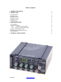
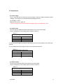
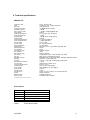
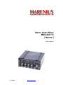
Stereo Audio Mixer MM-4220 T/C | Manual | Version 1.03 T/C 6/18/2009 www.marenius.se Table of contents 1. GENERAL DESCRIPTION 1 2. CONNECTIONS 2 2.1 POWER SUPPLY 2.2 AUDIO INPUTS 2.3 AUDIO OUTPUTS 2.4 PHONES OUTPUT 2.5 DIGITAL OUTPUT 2.6 USB SOCKET 2 2 2 3 3 4 3. USER INSTRUCTIONS 5 3.1 AUDIO MIXER 3.2 AUDIO RECORDER 3.2.1 16 / 24 bits mode selection 3.2.2 Checking recording buffer state 3.3 SETTING THE INTERNAL CLOCK 3.4 TIME CODE SYNCHRONIZATION (JAM) 3.5 POWER SUPPLY 4. TECHNICAL SPECIFICATIONS 6/18/2009 5 6 6 7 7 8 8 9 www.marenius.se 1. General description MM-4220 includes: 4 low-noise mic/line inputs Compact Flash recorder Re-chargeable batteries Heavy-duty metal case Compact size 1 kHz test tone 48V phantom power AES3-id digital out LTC time code jam input A highly accurate crystal oscillator The MM-4220 is a true professional stereo Mixer for portable use, made by MARENIUS. It offers four mic/line input channels, built-in Compact Flash card recorder, PPM metering with 2 x 8 multicolored LED’s, low-noise amplifiers and power supply based on re-chargeable NiMH cells for up to 8 hours use. All this is housed in a compact, all-metal heavy-duty case. The front panel holds all controls for the mixer. On top of the panel are toggle switches for Power, Test Tone and Battery Test. 48V phantom power may be selected for 0, 2 or 4 inputs. Each of the four channels has a gain control pot and a pan pot. In addition there is a gain selector switch for 0, 24 or 48 dB gain. The gain pot adds up to 12 dB and the master pot adds another 12 dB for a total of 72 dB gain, input-to-output. There is also a toggle switch for inserting a HP-filter for wind and bass cut. On the upper part of the front panel is the PPM bar graph with 16 multicolor LED’s covering the range -50 to 0 dB in optimized step size. You will also find the master pot and the headphones pot, as well as a switch for selecting 48V phantom power for 0, 2 or 4 channels. The CF card slot will accept up to 16 GB cards. Recordings are saved in uncompressed WAV format on FAT32 formatted cards. Recordings are stereo, 16-24 bits @ 48 kHz, selectable in setup menu by a PC connected to the USB port, or by front panel switches during power-up. The backside panel holds all sockets for inputs, outputs and external power supply. There are four input sockets (XLR-3F) for the input channels and two sockets (XLR-3M) for the main outputs L and R. A 3.5 mm stereo socket is intended for headphones (32 - 2000 ohms impedance). There is also an AES3-id RCA socket output and a USB socket for configuration of the mixer. External power supply can be used for prolonged working time or when the mixer is used in a non-portable mode. The external power should be 18 V @ 1 A. When powered from internal accumulator, expect a total working time of 6-8 hours, depending on battery status and temperature. A high-speed charger function is included for a charging time of about 2.5 hours. Along with a specially made cable connected to the USB port a LTC time code signal may be connected for jamming the internal clock to frame accuracy. 6/18/2009 1 2. Connections 2.1 Power supply The 2.1 mm power jack on the back of the unit accepts a clean DC voltage for powering and/or charging. The polarity can be switched without damaging the mixer. Input voltage: 18 VDC Minimum input current: 1000 mA ! Caution: Voltages above the recommended supply voltage can damage the device. 2.2 Audio inputs The mixer has four balanced XLR3 female sockets for mic or line level signals. The pin configuration of the analog inputs is shown in table 2.1. Table 2.1 Balanced analog audio input Connector type Ground Hot Cold XLR Female Pin 1 Pin 2 Pin 3 In case a line level signal is connected, make sure the 48V front panel switch is set to OFF (mid position). For an unbalanced line level signal connect in accordance with table 2.2. Table 2.2 Unbalanced analog audio input Connector type Ground Signal Ground XLR Female Pin 1 Pin 2 Pin 3 2.3 Audio outputs There are two balanced XLR3 male sockets for line level outputs. The pin configuration of the analog outputs is shown in table 2.3. Table 2.3 Balanced analog audio output Connector type Ground Hot Cold 6/18/2009 XLR Male Pin 1 Pin 2 Pin 3 2 For an unbalanced line level output signal connect in accordance with table 2.4. Table 2.4 Unbalanced analog audio output Connector type Ground Signal Do not connect! XLR Male Pin 1 Pin 2 Pin 3 2.4 Phones output The headphones output is a 3.5 mm 3-pole socket for standard headphones with an impedance equal to 32 - 2000 ohms. Table 2.5 Phones output Connector type Ground Left Right 3.5 mm, 3-pole sleeve tip ring 2.5 Digital output The digital audio output conforms to the AES3-id format. This is essentially a professional AES/EBU format in an unbalanced RCA socket. Data format is AES/EBU3 while electrical interface is equal to that for coaxial S/PDIF (0.5 Vpp, 75 ohms). Table 2.6 Unbalanced digital audio output Connector type Hot Ground 6/18/2009 RCA Center Chassis 3 2.6 USB socket The mixer has a mini-USB socket for connection to a PC for setting the internal real-time clock. This is used for adding a time-stamp to each recording. Instructions for setting the clock are described in chapter 3.3 in this manual. The USB socket is also used for setting 16 or 24 bits recording resolution. Along with a specially made cable connected to the USB port a LTC time code signal may be connected for jamming the internal clock to frame accuracy. This cable uses pin 4 for LTC signal and pin 5 for GND. The LTC signal level should be approx. 1 Vp-p for proper jamming. The USB socket may also be used for software updates. Instructions for use are included with the update, when available. Check for updates frequently at http://www.marenius.se. 6/18/2009 4 3. User instructions 3.1 Audio Mixer The audio mixer functions are very straight-forward. Connect desired number of microphones and/or line level input signals to the XLR sockets INPUT1 - 4 on the back panel. If required, connect the output signal from the XLR sockets OUTPUT LEFT and RIGHT. If required, connect a headphone to the phones socket. If required connect the digital output to an external unit with a suitable digital input. If available, use mains power supply through the mains adapter/charger unit. Set the 48V switch to off, mid position. Power-on the mixer by the toggle switch POWER. Check battery status by setting TEST switch to BAT position. The lower meter will indicate the battery status between 0% and 100%. Turn gain control knobs 1 – 4 fully down, anti-clockwise. Set MASTER knob to 0 dB. Switch on the 1 kHz TEST tone, left position. The test tone is a highly stable and very low-distortion sine wave. The output signal on the XLR sockets is 12 dB higher than what is indicated by the PPM meter. This is because MM-4220 is basically a digital mixer/recorder with a maximum signal level = 0 dB. At this maximum level the maximum output level on the XLR line outputs is +12 dBu. Calibrate the gain in external analog equipment that is connected to the XLR line output sockets. (Equipment connected to the digital output needs no gain calibration.) MM-4220 is now ready to be used as an ordinary mixer. Select 48V phantom power for microphone inputs 1 and 2 or 1, 2, 3 and 4 if required. Note that the sum of all phantom currents used must not exceed 5 mA. Also note that phantom power does drain the battery more. Adjust gain for each input by turning the knob and setting the 3-way gain switch in 0/24/48 dB position, as required. Adjust panning by turning the PAN pot. Select low-cut HPF filter if required. This may be useful for cutting wind noise. Adjust the phones knob for a good listening level with headphones. The MASTER knob may be used for adjusting the sum of all inputs. However, it is advised that it is left in the range close to 0 dBu. Setting master knob to a low value while any of the inputs has too much gain will result in distortion. On the other hand, setting the master knob to a high value while the inputs are set to low gain may increase the noise level. Use of the input knobs at the lower range, below -12 dB, is not recommended with high level signals. In that case, reduce pre-gain by the gain switch. If this is already set to 0 dB then the signal level is too high and external attenuation is required. Maximum input level is + 12 dBu (3 Vrms). Good audio mixing is a matter of balance between noise floor and clipping level, for maximum dynamic range. 6/18/2009 5 3.2 Audio Recorder The Compact Flash Recorder is located close to the left edge of the front panel. Before use a formatted CF card is required. Uses a suitable CF card adapter connected to a PC (or Mac) and format the card according to the FAT32 standard. Any other formats will be useless in MM-4220. Suitable CF cards have a capacity between 2 GB and up. High-speed cards are preferred. For 24 bits recordings this is required. Some example CF cards that usually work with this mixer are KINGSTON 133x and 266x and SANDISK Ultra III. Do not put any other files onto the card, only files generated by MM-4220 should be on it. The card fits into the front panel slot, facing left. When a CF card is inserted and found to be correct the MODE LED will be violet, Otherwise it will be blue. There are five keys for controlling the recorder: >> >> is used for skipping forward between recordings and within recordings. This key is valid only while in playback mode. A brief press will skip to next file (unless file played is the last recorded). Press-hold will skip forward within the file. << << is used for skipping backwards between recordings and within recordings. This key is valid only while in playback mode. A brief press will skip to previous file (unless file played is the first recorded). Press-hold will skip backwards within the file. This is the STOP key. It will end a recording and save the file with a new file number. In playback mode it will halt playback and return the mixer outputs to mixer mode. This is the RECORD key. Pressing it will immediately start a new recording. The MODE LED will turn red. This is the PLAYBACK key. The last file recorded will play back when this key is pressed. The MODE LED will turn green. Pressing it again will enter PAUSE mode and the MODE LED will flash. Files are recorded in uncompressed standard Wav-format with 48 kHz sample rate and 16 or 24 bits resolution. The files are automatically numbered REC00000.wav and up. Each file will get a correct time stamp, provided the real-time clock has been set correctly. Maximum length for a single file is 2 hours. Files recorded may be played back in any PC or Mac directly from the CF card, with a suitable CF card reader. 3.2.1 16 / 24 bits mode selection For selecting 24 bits recording mode, hold the >> >> key while powering on the mixer. The bar graph will show 3 + 3 LEDs lit. For selecting 16 bits recording mode, hold the << << key while powering on the mixer. The bar graph will show 2 + 2 LEDs lit. 6/18/2009 6 3.2.2 Checking recording buffer state The recording buffer is an on-board memory that holds enough samples for compensating for the periodically slower CF card. With some CF cards and, in particular, in 24 bits mode there may be risqué for buffer overrun. To see the buffer status, press both keys >> >> and << << while in recording mode. The bar graph will show a low level for a good state and a higher level for buffer problem. In case of buffer overrun recording mode is cancelled. 3.3 Setting the internal clock There are a few steps to perform in order to set the clock. 1. Download the most suitable Windows or Mac driver for the USB COM port from http://www.ftdichip.com/Drivers/VCP.htm and unzip the files to a separate folder. 2. Power on MM-4220. IMPORTANT! Power on the mixer before connecting the USB cable. Also, remove the CF card, if one is inserted! 3. Connect a USB cable between the PC and MM-4220. Avoid using a USB hub; a direct USB socket is preferred. 4. The ‘found new hardware’ wizard starts. Follow the on-screen instructions, pointing the wizard to the folder where the unzipped driver files are located. If a window appears with a note about the driver not being verified, agree to install anyway. 5. When done a message will show up indicating that the driver for a USB serial converter has been installed. 6. To see what COM port number has been assigned to the USB COM port, look into the Control Panel / Hardware Devices / Ports. 7. Use terminal software of your choice. An example is Tera Term, available for free from http://www.ayera.com/teraterm/. 8. Run the terminal software and make sure to select the COM port that was previously indicated to be used for the MM-4220 connection. Communication parameters are 9600, N, 8, 1. 9. Hit <Enter>. A short menu will show up: T Set time D Set date R Recording resolution C Time code (Only for MM-4220TC) Q Quit 10. When done, power off MM-4220 and disconnect the USB cable. 6/18/2009 7 3.4 Time code synchronization (jam) The internal clock is driven by a highly accurate clock oscillator. It is possible to synchronize the clock with an external LTC time code signal. Note that only hh:mm:ss:ff will be synchronized, yy:mm:dd (year/month/date) will not be affected. Perform the following steps for correct time code synchronization: 1. Follow the steps outlined in 3.3 to enable time code mode and also set the clock to correct date. 2. Use the specially made cable (optional) with a mini-USB plug and a XLR-3F socket. 3. Power on the mixer and connect the cable to the mixer’s USB socket and to a suitable LTC signal source. Note that only XLR pin 2 is used, with pin 1 = GND. 4. Press and hold the STOP key 5. The bar graph will flash once per second while jamming. 6. Release the STOP key after a few flashes and disconnect the cable. The internal clock is now synchronized to the external LTC time code. Whenever a new recording starts the time code data will be written in the BWF file header. Note that a new recording will always start on the increment of seconds; hence the frame number written is 00. 3.5 Power Supply MM-4220 runs from an internal NiMH power pack. This is a high capacity pack with rechargeable accumulators for a full working day without need for additional charging. The included mains adapter/charger unit can be used for both charging and powering the mixer. The power supply has a 2.1 mm plug, polarity is any. For both powering and charging the minimum current capacity must be 1 A @ 18 V DC. When connected the LED next to the socket will be lit red. When the mixer is fully charged the LED will be lit green. This may take up to 2.5 hours for a fully discharged unit. There is no need to discharge the unit before charging. The internal, intelligent charging circuitry handles the complete charging cycle. 6/18/2009 8 4. Technical specifications MM-4220 T/C Frequency range THD Max. gain Signal-to-noise ratio Crosstalk at full pan Equiv. input ref. noise Input sockets Audio input impedance Audio input level max. High-pass filter Output sockets Audio output impedance Audio output level max. Phones socket Phones output Phones impedance Digital output Sampling frequency A/D resolution A/D dynamic range D/A resolution D/A dynamic range File memory File type Recorder functions Metering Test tone Real-time clock accuracy LTC jam input Ltc jam input signal level Phantom power Power supply Current drain Charge current Size W x H x D Weight Battery charger Carrying case 25 Hz - 22 kHz (-3 dB) <0,004% @ 1 kHz, +12 dBu output level 72 dB (48+12+12) >94 dB@0 dB gain, A-weight <-50 dB <-122 dBu, A-weighted @max gain XLR-3F 2 K ohms (mic), 20 K ohms (line) +12 dBu -3 dB @ 180 Hz, -20 dB @ 30 Hz XLR-3M 2 x 100 ohms balanced +12 dBm (600 ohms) 3.5 mm 3-pole 2.0 Vrms into 300 ohms 32 - 2000 ohms AES3-id, 75 ohms, 1 Vpp, S/PDIF compatible, RCA 48 kHz 24 bits 98 dB, A-weighted 24 bits 98 dB, A-weighted Compact Flash, type I, FAT32 formatted, max 16 GB BWF, stereo, uncompressed, 48/16-24 RECORD, STOP, PLAY, FFWD, FREV, SKIPFWD, SKIPREV, PAUSE 2x8 LED´s, 3 colors, PPM mode 1000 Hz +/-0,001% @ -12 dBFS (0 dBu) output level +-2 ppm USB socket pin 4, GND = pin 5 300 mVp-p to 3 Vp-p 48 V+-6 V, max 5 mA @ 90% internal NiMH or ext. 18 V DC@1 A <220 mA 750 mA approx. 140 x 60 x 136 mm, excl. sockets and knobs approx. 950 grams included, 90-240 VAC PortaBrace original, optional Specifications are subject to change without notice. Box contains: Qty Item 1 1 1 1 1 MM-4220 Stereo Mixer / Recorder Mains adapter / charger 18V CF card USB cable User´s manual Option: 6/18/2009 Time Code jam cable 9