1
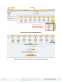
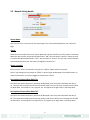
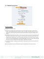
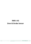
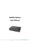
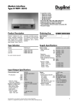
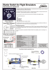
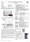
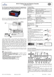
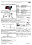
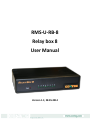
RMS-U-RB-8 Relay box 8 User Manual Version 1.1; 28.05.2014 © 2013 CONTEG, spol. s r.o. All rights reserved. No part of this publication may be used, reproduced, photocopied, transmitted or stored in any retrieval system of any nature, without the written permission of the copyright owner. Although this manual was prepared and checked with the best care, CONTEG, spol. s r.o. cannot accept any liability for omissions or errors in this publication. Due to the continuous development and progress, CONTEG, spol. s r.o. also reserves the right to change details and technical specifications of the products described in this manual. Such changes along with eventual errors or printing errata shall not constitute grounds for compensation. 2 Content 1. 2. 3. Introduction .......................................................................................................................................... 3 1.1. What is RMS-U-RB-8?.................................................................................................................... 3 1.2. Where to use this RMS-U-RB-8? ................................................................................................... 3 Installing and configuring the Relay Box 8 ............................................................................................ 4 2.1. Plug it on intelligent sensor port ................................................................................................... 4 2.2. Log in ............................................................................................................................................. 4 2.3. Go on Sensor tab ........................................................................................................................... 4 2.4. Setting ........................................................................................................................................... 4 2.5. Normal Setting details................................................................................................................... 6 2.6. Advanced Setting details ............................................................................................................... 7 Relay Box 8 specification: ..................................................................................................................... 8 1. Introduction 1.1. What is RMS-U-RB-8? The Relay Box 8 allows for remote use of electrical devices over the Internet. It provides eight highpower SPDT 5V relays in one array. It includes Metal Oxide Varistors (MOVs) and Snubber circuits to protect the open contact of the relays from high-voltage spikes or noise transients. It monitors the power load and accepts a control signal which is sent from the unit. The RMS-U-RB-8 is designed to work with the RAMOS Ultra only. 1.2. Where to use this RMS-U-RB-8? Power Switch On/Off Control Activate Alarms Process Control Energy Management Systems 3 2. Installing and configuring Relay Box 8 2.1. Plug it into intelligent sensor port Plug the sensor into one of the RJ45 ports on the rear panel of the unit. If you are going to use more than 1 Relay Box 8 unit, then a 7.5 volt, 3A external power supply is required. 2.2. Log in Type the IP address of the RAMOS Ultra unit (default, 192.168.0.100) into your web browser. Log in as the administrator using your administrator password (default: public). You will then be taken to the summary page. 2.3. Go to “Sensors” tab From the summary or main page, you need to select the “Sensors” tab. The layout of the next page will vary depending on your unit, so please refer to your unit’s manual. 2.4. Setting You should now be able to configure the settings of your Relay Box, including the sensor name, the descriptions of each relay status, the relay control mode, etc. The first screen shot below shows our 8 Port Sensor Control Relay on port 8 of our unit Move cursor over the intelligent port where is connected the Relay Box 8. You will be able to see all relays and select each for individual settings, including advanced settings. 4 The each line present one relay and with click you will open a setting. Click on a relay to open setting shown below: Each relay setting is entered on this page, including the advanced settings. 5 2.5. Normal Setting details Sensor Name: Here you can enter a new name for the relay output. This name will be displayed on the “Summary” page. Status: Shows the current state of the relay output. When the relay box is offline, the relay status is “No Status”. When the relay is online and its Normal State field is “ON”, then the status is “Normal”. When the relay is online and its Normal State Field is “OFF”, then the status is “Critical”. If at any time, communications with the Relay Box 8 are lost, the status is changed to “Sensor Error”. Sensor currently: Click to switch “online” (activate this relay port) or “offline” (deactivate the relay port). Note: if you change the relay output to “offline” it will no longer be displayed on the web interface. In order to reactivate it, you have to toggle the relay back to “online”. Description of Status When Relay On: This field is the custom description, which will be displayed in the relay status field when the relay is on. The same text is listed as one of the relay actions used to turn on the relay. Examples for this field are Open Door, Turn Pump On, Turn Light On, etc. This applies to all eight relays in the Relay Box 8. Description of Status When Relay Off: This field is the custom description, which will be displayed in the relay status field when the relay is off. The same text is listed as one of the relay actions used to turn off the relay. Examples for this field are Close Door, Turn Pump Off, Turn Light Off, etc. This applies to all eight relays in the Relay Box 8. 6 2.6. Advanced Setting details Relay Control Mode: Configuration examples include: a) Manual Control allows you to manually control each of the eight relays using the “Relay Control” option. You will be able control the cycle of the relay in an on-off-on or an off-on-off cycle. You can also set the “Cycle Time” here in seconds and manually test each relay using the “Test Relay Cycle” button. b) Notification Control allows you to link any of the relays to an action. The actions can be selected from the “Action” drop-down menu after clicking on “To set notification controlled relay click here”. The following actions can be chosen: Turn on until sensor normal; turn off until sensor normal; cycle the relay; turn on until acknowledged; turn off until acknowledged. You can also turn the “Sensor Normal Relay State” to on or off and test each relay using the “Test Relay Cycle” button. c) Time Control: Displays a calendar to setup what days and times you want or do not want each relay to be active. d) Thermostat: Option to select a thermostat for ports 1 through 8 which will control the relay. 7 3. Relay Box 8 specification: Power Supply: 7.5VDC 3A “RMS-U-PW” is required. Relay contacts rated at 15 A @ 220 VAC, 25VDC with Resistive Load 8 A @ 220 VAC, 25VDC with Inductive Load (P.F=0.4, L/R=7 mS) Contact Material AgCdO Max. Operating Voltage: 380 VAC, 125 VDC Max. Switching Capacity: 4,000 VA, 480W with Resistive Load 2,000 VA, 240W with Inductive Load (P.F=0.4) Power Consumption: Typically 2.5 W, 0.5A Communications cable - RJ-45 jack to sensor using UTP Cat 5 wire. Sensor type: Open/Close contact switches (8) The unit auto detects the presence of Relay Box 8 Full autosense including disconnected alarm Metal Oxide Varistors (MOVs) and Snubber circuit protect the open contacts of the relays from high voltage spike. LEDs across the front panel indicate the status of each Relay and the Power Supply. Dimensions : 216(W) x 138(H) x 46(D) mm Operating Temperature: -40°C to 85°C Storage Temperature: -40°C to 85°C 8