1
• SAFETY PRECAUTIONS •
(Be sure to read these instructions before using the product.)
Before using this product, read this manual and the relevant manuals introduced in this manual carefully
and handle the product correctly with full attention to safety.
Note that these precautions apply only to this product. Refer to the user's manual of the CPU module for
safety precautions on programmable controller systems.
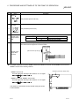
In this manual, the safety instructions are ranked as "DANGER" and "CAUTION".
DANGER
Indicates that incorrect handling may cause hazardous conditions,
resulting in death or severe injury.
CAUTION
Indicates that incorrect handling may cause hazardous conditions,
resulting in minor or moderate injury or property damage.
Note that failure to observe the ! CAUTION level instructions may also lead to serious results depending
on the circumstances.
Be sure to observe the instructions of both levels to ensure personal safety.
Please keep this manual in accessible place and be sure to forward it to the end user.
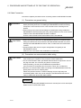
[Design Instructions]
!
DANGER
• Make sure to see this manual for information about each station's operating status when a
communication error occurs in the network. Erroneous outputs and malfunctions may result in
serious accidents.
• If a coaxial cable is disconnected, this may destabilize the line, and a data link communication
error may occur in multiple stations. Make sure to create an interlock circuit in the sequence
program so that the system will operate safely even if the above error occurs. Failure to do so
may result in a serous accident due to faulty output or malfunctions.
• Provide a safety circuit outside the programmable controller so that the entire system will
operate on the safety side even when an error occurs with the personal computer.
There is a risk of an accident due to faulty output or malfunctioning.
(1) Construct circuits outside the programmable controller, including an emergency stop circuit,
protection circuit, interlock circuit for reciprocal operations such as forward and reverse, and
interlock circuit for positioning high and low limits to prevent damage to the equipment.
(2) If the station in which the MELSECNET/H board (Q80BD-J71LP21-25/Q81BD-J71LP2125/Q80BD-J71LP21S-25/Q80BD-J71LP21G/Q80BD-J71LP21GE/Q80BD-J71BR11) is
installed is disconnected from the data link due to a data link error, the data output from that
station and written in other stations will remain the same as immediately before the error
occurred in the data link. This data will be retained until the data link for that station is
reopened (returned to system).
Provide a mechanism to monitor the status of data link and handle errors for each station
that is connected to the data link system.
A-1
A-1
[Design Instructions]
!
CAUTION
• Do not bunch the control wires or communication cables with the main circuit or power wires, or
install them close to each other.
They should be installed 100 mm (3.94 inch) or more from each other.
Not doing so could result in noise that would cause malfunctioning.
[Installation Instructions]
!
CAUTION
• Use the MELSECNET/H board in an environment as described in the general specifications
listed in this operating manual.
If the board is used in an environment outside the ranges described in the general
specifications, it may result in an electric shock, fire, malfunctioning, damage to or deterioration
of the product.
• Be sure to shut off all phases of the external power supply used by the system before installing
or removing the MELSECNET/H board. If all power is not turned off, this will result in failure of
the MELSECNET/H board or malfunctioning.
• Securely mount the MELSECNET/H board to the PCI bus slot of the mounting device.
If the MELSECNET/H board is not mounted correctly, this may lead to malfunctioning, failure or
cause the board to fall.
• Insert the communication cable securely into the MELSECNET/H board connector. After it has
been inserted, check to make sure that it is not being lifted up.
A faulty connection can lead to faulty input or output.
• When mounting the MELSECNET/H board, take care not to become injured by the components
that are installed or surrounding materials.
• Always make sure to touch the grounded metal to discharge the electricity charged in the body,
etc., before touching the MELSECNET/H board.
Failure to do so may cause a failure or malfunctions of the MELSECNET/H board.
A-2
A-2
[Wiring Instructions]
!
DANGER
• Be sure to shut off all phases of the external power supply used by the system before
performing work such as installing the MELSECNET/H board and wiring.
If all power is not turned off, there is a risk of electric shock or damage to the product.
• When turning on the power and operating the module after having installed the MELSECNET/H
board and doing the wiring, always attach the cover for the device module in which the
MELSECNET/H board is installed.
There is a risk of electric shock if the module cover is not attached.
!
CAUTION
• Solder the coaxial cable properly.
If the soldering is incomplete, it may cause the module malfunction.
• For the communication cable, specialized skills and tools are required to connect the plug and
cable. The connector plug itself is a custom part.
When purchasing, consult your local Mitsubishi representative.
If the connection is incomplete, this can result in a short, fire or malfunction.
• Be sure to fix communication cables connecting to the MELSECNET/H board by placing them in
the duct or clamping them.
Cables not placed in the duct or without clamping may be hang freely and accidentally pulled,
which may cause damage to the MELSECNET/H board or cable, or malfunction due to bad
cable contacts.
• When removing the cable from the MELSECNET/H board, do not pull the cable.
Pulling the cable that is still connected to the MELSECNET/H board may cause damage to the
MELSECNET/H board or cable, or malfunction due to bad cable contacts.
• Prevent foreign matter such as chips or wiring debris from getting on the MELSECNET/H board.
Failure to do so can result in fire, breakdowns or malfunction.
• Verify the rated voltage and pin assignment of the product and connect the external power
supply cable properly.
Connecting a power supply with a different voltage rating, imperfect cable crimping or faulty
wiring may cause a fire or failure.
• Use a specified tool for crimping of the cable and contacting pin. Imperfect crimping may cause
malfunction.
• Verify the pin assignment and fully insert the crimped contacting pin into the connector.
Imperfect insertion may cause failure or malfunction.
• Insert the wired external power supply cable into the external power supply cable connector until
a click is heard. Imperfect insertion may cause failure or malfunction.
• Keep the external power supply cable away from the main circuit cable, power cables and/or
load cables connected to other than programmable controllers. Ensure a distance of 100mm
(3.94 in.) between them. Failure to do so may result in malfunction due to noise, surge or
induction.
• Always ground the personal computer. Failure to do so may cause malfunction.
A-3
A-3
[Startup/Maintenance Instructions]
!
DANGER
• Do not attach or remove the communication cable while the power supply is on.
This may result in malfunctioning.
• Tighten the board fixing screws after turning off the power supply.
There is a risk of electric shock if the screws are tightened while power is on.
!
CAUTION
• Thoroughly read the operating manual and carefully check to make sure everything is safe
before performing operations such as making changes to the program while the module is
operating, forced outputs, RUN, STOP and PAUSE.
Operation errors will result in damage to the equipment or accidents.
• Do not dismantle or rebuild the MELSECNET/H board.
This will result in breakdowns, malfunctioning, injury or fire.
• Be sure to shut off all phases of the external power supply used by the system before installing
or removing the MELSECNET/H board.
If all power is not turned off, this will result in failure of the MELSECNET/H board or
malfunctioning.
• The MELSECNET/H board internal microprocessor reaches very high temperatures when it is
running. Do not touch it directly when replacing the MELSECNET/H board.
This will result in breakdowns, malfunctioning or injury.
• Always make sure to touch the grounded metal to discharge the electricity charged in the body,
etc., before touching the MELSECNET/H board.
Failure to do so may cause a failure or malfunctions of the MELSECNET/H board.
[Disposal Instructions]
!
CAUTION
• When disposing of this product, treat it as industrial waste.
A-4
A-4
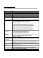
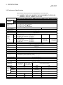
REVISIONS
The manual number is given on the bottom left of the back cover.
Print Date
Manual Number
Nov., 2000 SH (NA)-080128-A First printing
Mar., 2001 SH (NA)-080128-B Model addition
Revision
Q80BD-J71LP21G, Q80BD-J71LP21GE
Correction
Section 1.3, Appendix 3.1
Jun., 2001 SH (NA)-080128-C
Correction
About the Generic Terms and Abbreviations, Section 1.2, Section 1.3,
Section 2.5, Section 7.1, Section 7.1.1, Section 7.1.2, Section 7.4,
Section 8.2.3, Section 9.1.2, Section 9.2, Section 10.3.2, Section 10.4,
Appendix 3, Appendix 3.1
Addition
Section 10.8, Section 12.2, Chapter 13
Jan., 2002 SH (NA)-080128-D
Correction
Section 2.5, Section 3.1, Section 3.2, Section 5.6, Section 9.1.2,
Section 10.7, Section 12.2, Section 12.2.2
Addition
About the Generic Terms and Abbreviations, Sections 9.1.2,
Chapter 13
Dec., 2002 SH (NA)-080128-E
Correction
Safety Precautions, Section 8.2.3, Section 8.2.8, Section 8.3.3,
Section 9.1.2, Chapter 10, Section 12.2, Appendix 3.1, Appendix 4.1,
Appendix 4.2
Addition
Precautions for use, Generic Terms and Abbreviations, Section 1.2,
Section 1.3, Section 2.5, Section 5.4.2, Section 7.1.1, Section 7.1.2,
Section 7.2, Section 7.3, Section 8.1.1, Section 10.3, Chapter 13,
Section 14.3, Section 14.3.1, Section 14.5.4, Section 14.6
May, 2004 SH (NA)-080128-F
Correction
Safety Precautions, Precautions for use, Section 3.1, Section 3.2,
Section 6.3.1, Section 8.2.5, Section 8.2.10, Section 12.2, Section 12.2.1,
Section 12.2.2, Section 12.2.3, Section 12.3.3, Chapter 13,
Section 14.4.4, Section 14.7, Appendix 5.1
Addition
Generic Terms and Abbreviations, Section 1.2, Section 1.3, Section 2.4,
Section 2.5, Section 4.2.1, Section 5.2.1, Section 5.3, Section 5.4.3,
Chapter 6, Section 6.3.6, Section 8.2.1, Section 8.2.3, Section 10.3,
Section 10.3.3, Section 10.3.4, Section 10.8, Section 11.3, Chapter 12,
Section 14.4, Section 14.5.5, Section 14.6, Appendix 3
A-5
A-5
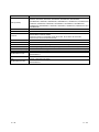
The manual number is given on the bottom left of the back cover.
Print Date
Manual Number
Revision
Dec., 2004 SH (NA)-080128-G Chapter numbers of 5 to 14 were changed to 6 to 15 respectively.
Correction
Precautions for use, Generic Terms and Abbreviations, Chapter 1,
Section 1.1, Section 1.2, Section 1.3, Section 2.1, Section 2.4,
Section 2.5, Section 3.2, Chapter 7, Section 7.1, Section 7.2.4,
Section 9.2.2, Section 9.2.3, Section 9.2.5, Section 9.2.10,
Section 9.2.11, Section 10.1.2, Section 10.2, Section 13.2.1,
Section 15.4.3
Addition
Section 2.6, Chapter 5, Section 15.7
Jun., 2005 SH (NA)-080128-H Model addition
Q80BD-J71LP21S-25
Correction
SAFETY PRECAUTIONS, INTRODUCTION,
Generic Terms and Abbreviations, Product List,
Section 1.2, Section 2.1, Section 2.5, Section 3.2, Section 4.1,
Section 6.1, Section 6.3, Section 6.4, Section 6.5, Section 6.6,
Section 7.2.1, Section 8.1.2, Section 9.2.2, Section 9.2.6,
Section 9.3.5, Section 11.4, Section 11.6, Section 12.3, Chapter 13,
Chapter 14, Section 15.2, Section 15.4.4, Section 15.6, Section 15.7,
Section 15.8, Appendix 4, Appendix 5
Addition
Section 6.4.4, Section 15.6, Appendix 4, Appendix 6.2
Jul.,2005
SH(NA)-080128-I
Correction
Section 2.5, Appendix 6.2
Oct.,2005
SH(NA)-080128-J
Correction
Section 2.5, Section 8.1.1, Section 8.1.2, Section 8.3, Section 9.1,
Section 15.2
Mar., 2007 SH(NA)-080128-K
Correction
Generic Terms and Abbreviations, Section 2.2.4, Section 2.5,
Section 6.4.1, Section 6.4.2, Section 8.1.1, Section 8.1.2, Section 10.1.2,
Section 10.2, Section 11.2, Section 11.6, Section 11.8, Section 15.4.5
Addition
Section 11.3.5, Section 11.3.6, Section 11.7
Oct., 2007
SH(NA)-080128-L
Correction
Generic Terms and Abbreviations, Section 1.2, Section 1.3, Section 2.5,
Chapter 5, Section 8.1.1, Section 8.3, Section 9.1, Chapter 14,
Section 15.2, Section 15.3.1
Section 8.1.2 changed to Section 8.1.3
Addition
Section 8.1.2, Appendix 5
A-6
A-6
The manual number is given on the bottom left of the back cover.
Print Date
Manual Number
Jan., 2008 SH(NA)-080128-M
Revision
Correction
Generic Terms and Abbreviations, Section 2.5, Section 6.5.1,
Section 6.5.2, Section 6.5.3, Section 6.6.1, Section 6.6.2, Section 8.1.1,
Section 8.1.3, Section 10.1.2, Section 10.2, Section 11.6, Section 11.7
May, 2008 SH(NA)-080128-N
Model addition
Q81BD-J71LP21-25
Correction
SAFETY PRECAUTIONS, Precautions for Use, INTRODUCTION,
Generic Terms and Abbreviations, Product List, Section 1.2,
Section 1.3, Section 2.1, Section 2.5, Section 3.1, Section 3.2,
Section 6.3, Section 6.4.1, Section 6.4.3, Section 6.5.1, Section 6.5.2,
Section 6.5.3, Section 6.6.1, Section 6.6.2, Section 8.1.1, Section 8.1.3,
Section 8.2, Section 8.3, Section 9.1, Section 9.1.1, Section 9.2.2,
Section 9.2.6, Section 10.1.2, Section 11.3, Section 15.2, Section 15.3,
Section 15.4.4
Appendix 3 to 6 changed to Appendix 2 to 5
Addition
Appendix 5.4
Deletion
Appendix 2, Appendix 2.1
Jun., 2008 SH(NA)-080128-O
Correction
Section 1.3, Section 2.5, Section 9.2.4, Section 15.4.4,
Appendix 4.2
Oct., 2008 SH(NA)-080128-P
Addition
Generic Terms and Abbreviations, Section 2.5, Section 10.1.2
Japanese Manual Version SH-080129-P
This manual confers no industrial property rights or any rights of any other kind, nor does it confer any patent
licenses. Mitsubishi Electric Corporation cannot be held responsible for any problems involving industrial property
rights which may occur as a result of using the contents noted in this manual.
© 2000 MITSUBISHI ELECTRIC CORPORATION
A-7
A-7
Precautions for Use
(1) Transfer function between loops and routing transfers
The MELSECNET/H board cannot be used as a relay station for the transfer
function between data links and during routing transfers.
If the transfer function between data links and routing transfers are used, use
the network module as a relay station.
(2) Remote I/O Network
The MELSECNET/H board cannot be used in a remote I/O net.
It can be used only in a PLC to PLC network.
(3) Multi-thread Communications
Multi-thread communications cannot be carried out.
(4) Multiprocessor-based personal computers
For details on the compatible operating system and driver software version
when using multiprocessor-based personal computers, refer to (2) in
Section 2.5.
(5) Compatibility with Hyper-Threading technology
For details on the compatible operating system and driver software version
when using the hyper-threading technology on the personal computer, refer to
(2) in Section 2.5.
(6) Operating environment of the personal computer used
Refer to Section 2.5 in this manual.
A-8
A-8
INTRODUCTION
Thank you for purchasing the Q80BD-J71LP21-25/Q81BD-J71LP21-25/Q80BD-J71LP21S-25/Q80BDJ71LP21G/Q80BD-J71LP21GE/Q80BD-J71BR11MELSECNET/H Interface Board.
Please read this manual carefully so that equipment is used to its optimum.
CONTENTS
SAFETY PRECAUTIONS..............................................................................................................................A- 1
REVISIONS ....................................................................................................................................................A- 5
Precautions for Use........................................................................................................................................A- 8
INTRODUCTION............................................................................................................................................A- 9
CONTENTS....................................................................................................................................................A- 9
Manuals ..........................................................................................................................................................A-14
How to Use This Manual................................................................................................................................A-15
Generic Terms and Abbreviations .................................................................................................................A-17
Meaning and Contents of the Terms .............................................................................................................A-19
Product List.....................................................................................................................................................A-19
1 OVERVIEW
1- 1 to 1- 8
1.1 Overview.................................................................................................................................................. 1- 1
1.2 Features .................................................................................................................................................. 1- 2
1.3 Combinations of Boards with Existing Software .................................................................................... 1- 5
2 SYSTEM CONFIGURATION
2- 1 to 2-12
2.1 MELSECNET/H Board System Configuration ....................................................................................... 2- 1
2.2 Single Network System........................................................................................................................... 2- 3
2.2.1 Optical loop system.......................................................................................................................... 2- 3
2.2.2 Coaxial bus system .......................................................................................................................... 2- 3
2.2.3 Setting items..................................................................................................................................... 2- 4
2.2.4 Usable device ranges....................................................................................................................... 2- 4
2.3 Multiple Network System ........................................................................................................................ 2- 5
2.3.1 Configuration .................................................................................................................................... 2- 5
2.3.2 Setting items..................................................................................................................................... 2- 6
2.3.3 Usable device range ........................................................................................................................ 2- 6
2.4 If used in a Multiple CPU System or Redundant CPU System ............................................................. 2- 7
2.5 Operating Environment........................................................................................................................... 2- 8
2.6 Checking Versions .................................................................................................................................. 2-11
3 SPECIFICATIONS
3.1
3.2
3.3
3.4
3- 1 to 3- 4
General Specifications ............................................................................................................................ 3Performance Specifications .................................................................................................................... 3Optical Fiber Cable Specification ........................................................................................................... 3Coaxial Cable Specification .................................................................................................................... 3-
A-9
A-9
1
2
4
4
4 FUNCTION
4- 1 to 4- 4
4.1 Function List ............................................................................................................................................ 4- 1
4.2 Specifications of the Link Data Sending/Receiving Processing Time................................................... 4- 2
4.2.1 Link data sending/receiving processing .......................................................................................... 4- 2
5 EMC AND LOW VOLTAGE DIRECTIVE
5- 1 to 5- 6
5.1 Requirements for Conformance to EMC Directive ................................................................................ 55.1.1 Standards applicable to the EMC Directive..................................................................................... 55.1.2 Installing devices in the control panel.............................................................................................. 55.1.3 Cables............................................................................................................................................... 55.1.4 Ferrite core ....................................................................................................................................... 55.1.5 Noise filter (power supply line filter)................................................................................................. 55.2 Requirements for Conformance to Low Voltage Directive .................................................................... 56 PROCEDURE AND SETTINGS UP TO THE POINT OF OPERATION
1
1
2
3
4
4
5
6- 1 to 6-28
6.1 Procedure Up to the Point of Operation ................................................................................................. 6- 1
6.2 Installation ............................................................................................................................................... 6- 2
6.2.1 Precautions when handling.............................................................................................................. 6- 2
6.2.2 Installation environment ................................................................................................................... 6- 2
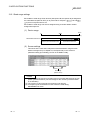
6.3 Names of Each Part and Their Settings................................................................................................. 6- 3
6.4 Cable Connection.................................................................................................................................... 6- 6
6.4.1 Optical loop system.......................................................................................................................... 6- 8
6.4.2 Coaxial bus system .......................................................................................................................... 6-10
6.4.3 Connecting the connector for the coaxial cable .............................................................................. 6-15
6.4.4 External power supply cable wiring ................................................................................................. 6-17
6.5 Standalone Check of the MELSECNET/H Board (Offline Tests).......................................................... 6-19
6.5.1 Self-loopback test............................................................................................................................. 6-20
6.5.2 Internal self-loopback test ................................................................................................................ 6-22
6.5.3 H/W test............................................................................................................................................ 6-24
6.6 Offline Tests ............................................................................................................................................ 6-25
6.6.1 Station to station test........................................................................................................................ 6-25
6.6.2 Forward loop/Reverse loop test....................................................................................................... 6-28
7 PARAMETER SETTINGS
7- 1 to 7-12
7.1 Board Information Settings ..................................................................................................................... 7- 2
7.2 Network Settings ..................................................................................................................................... 7- 3
7.2.1 Network No....................................................................................................................................... 7- 3
7.2.2 Station No......................................................................................................................................... 7- 3
7.2.3 Control station/Normal station ......................................................................................................... 7- 3
7.2.4 Group No. ......................................................................................................................................... 7- 4
7.2.5 Mode setting ..................................................................................................................................... 7- 4
7.2.6 Parameter setting example.............................................................................................................. 7- 5
7.3 Common Parameters.............................................................................................................................. 7- 6
7.3.1 Send range for each station (LB/LW settings) ................................................................................ 7- 6
7.3.2 Send range for each station (LX/LY settings) ................................................................................. 7- 8
A - 10
A - 10
7.3.3 Total station ...................................................................................................................................... 7-10
7.3.4 Designation of the I/O master station .............................................................................................. 7-10
7.3.5 Reserved station setting .................................................................................................................. 7-10
7.3.6 Pairing Setting .................................................................................................................................. 7-10
7.4 Supplementary Setting ........................................................................................................................... 7-11
7.5 Control Station Return Setting................................................................................................................ 7-12
8 INSTALLING AND UNINSTALLING THE SOFTWARE PACKAGE
8- 1 to 8-22
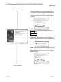
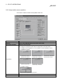
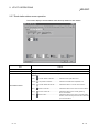
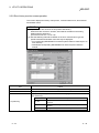
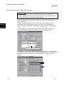
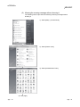
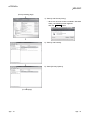
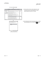
8.1 Installation ............................................................................................................................................... 8- 1
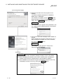
8.1.1 Installing the Driver........................................................................................................................... 8- 2
8.1.2 Updating the Driver .......................................................................................................................... 8-10
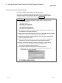
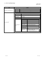
8.1.3 Installing the utility ............................................................................................................................ 8-12
8.2 Icons to be Registered ............................................................................................................................ 8-19
8.3 Uninstalling the Software Package......................................................................................................... 8-20
8.4 Copying the Program to Floppy Disks, then Installing It........................................................................ 8-22
9 UTILITY OPERATIONS
9- 1 to 9-40
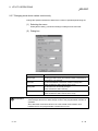
9.1 Utility Common Operations..................................................................................................................... 9- 1
9.1.1 Starting an utility............................................................................................................................... 9- 1
9.1.2 Ending an utility ................................................................................................................................ 9- 2
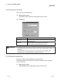
9.1.3 Displaying the help screen............................................................................................................... 9- 3
9.1.4 Verifying the version......................................................................................................................... 9- 4
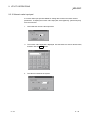
9.2 MNETH Utility.......................................................................................................................................... 9- 6
9.2.1 Operating procedure ........................................................................................................................ 9- 6
9.2.2 Board list screen operation .............................................................................................................. 9- 7
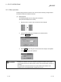
9.2.3 Board information screen operation ................................................................................................ 9- 9
9.2.4 Routing Parameter Setting screen operation.................................................................................. 9-11
9.2.5 Common parameter setting screen operation................................................................................. 9-12
9.2.6 Loop monitor screen operation........................................................................................................ 9-16
9.2.7 Each station status screen operation .............................................................................................. 9-17
9.2.8 Error history monitor screen operation ............................................................................................ 9-18
9.2.9 Memory, I/O Test screen operation................................................................................................. 9-21
9.2.10 Target screen operation................................................................................................................. 9-22
9.2.11 Driver screen operation.................................................................................................................. 9-23
9.3 Device Monitor Utility .............................................................................................................................. 9-26
9.3.1 Operation procedure ........................................................................................................................ 9-26
9.3.2 Setting as batch monitoring ............................................................................................................. 9-27
9.3.3 Setting as 16 point entry monitor..................................................................................................... 9-28
9.3.4 Setting the monitoring destination ................................................................................................... 9-29
9.3.5 Setting the device to be monitored .................................................................................................. 9-30
9.3.6 Changing word device values.......................................................................................................... 9-31
9.3.7 Changing word device values continuously .................................................................................... 9-32
9.3.8 Tuning on/off a bit device................................................................................................................. 9-33
9.3.9 Switching the display form ............................................................................................................... 9-33
9.3.10 Numeric value input pad ................................................................................................................ 9-34
9.3.11 Other operations ............................................................................................................................ 9-35
A - 11
A - 11
9.4 Error Viewer Operation ........................................................................................................................... 9-37
9.4.1 Screen description ........................................................................................................................... 9-37
9.4.2 Log menu.......................................................................................................................................... 9-38
9.4.3 Display menu.................................................................................................................................... 9-39
10 ACCESSIBLE DEVICES AND RANGES
10- 1 to 10- 6
10.1 Accessible Devices ............................................................................................................................. 1010.1.1 Host (personal computer (control/normal station equivalent)).................................................... 1010.1.2 Other station................................................................................................................................. 1010.2 Accessible Range ............................................................................................................................... 1011 MELSEC DATA LINK LIBRARY
1
1
2
5
11- 1 to 11-14
11.1 Overview of the MELSEC Data Link Library...................................................................................... 11- 1
11.2 Function List ........................................................................................................................................ 11- 2
11.3 Settings for Using Functions............................................................................................................... 11- 3
11.3.1 When using Visual Basic 5.0 and Visual Basic 6.0................................................................. 11- 3
11.3.2 When using Visual C++ 5.0 and Visual C++ 6.0..................................................................... 11- 3
11.3.3 When using Visual Basic .NET 2003......................................................................................... 11- 4
11.3.4 When using Visual C++ .NET 2003........................................................................................... 11- 4
11.3.5 When using Visual Basic 2005 .................................................................................................. 11- 5
11.3.6 When using Visual C++ 2005 .................................................................................................... 11- 6
11.4 Procedure for Programming ............................................................................................................... 11- 9
11.5 Channel ............................................................................................................................................... 11-11
11.6 Station Number Settings..................................................................................................................... 11-11
11.7 Network Number and Station Number Specification for Extended Functions .................................. 11-11
11.8 Device Types ...................................................................................................................................... 11-12
11.9 Sample Programs ............................................................................................................................... 11-14
R
R
R
R
R
R
R
R
12 PROGRAMMING
12- 1 to 12- 6
12.1 Cautions in Programming ................................................................................................................... 1212.1.1 Interlock related signals ............................................................................................................... 1212.2 Cyclic Transmission ............................................................................................................................ 1212.2.1 Block guarantee of cyclic data per station................................................................................... 1212.3 Link Special Relays (SB)/Registers (SW) .......................................................................................... 1213 APPLICATION FUNCTIONS
1
1
3
4
5
13- 1 to 13-22
13.1 Direct Access to the Link Devices ...................................................................................................... 13- 1
13.2 Low-Speed Cyclic Transmission Function ......................................................................................... 13- 2
13.2.1 Send range settings ..................................................................................................................... 13- 3
13.2.2 Send timing................................................................................................................................... 13- 4
13.2.3 Startup .......................................................................................................................................... 13- 7
13.3 Transient Transmission Function ....................................................................................................... 13- 9
13.3.1 Communication function .............................................................................................................. 13-10
13.3.2 Routing function ........................................................................................................................... 13-13
13.3.3 Group function.............................................................................................................................. 13-21
13.4 Multiplex Transmission Function (Optical Loop System) .................................................................. 13-22
A - 12
A - 12
14 ERROR CODE
14- 1 to 14- 8
15 TROUBLESHOOTING
15- 1 to 15-24
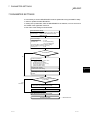
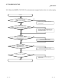
15.1 When Performing Troubleshooting .................................................................................................... 15- 1
15.2 Cause Determination Methods by Type of Trouble........................................................................... 15- 2
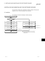
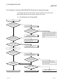
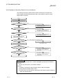
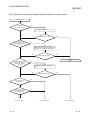
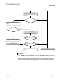
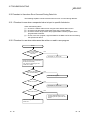
15.3 Flowchart to Use when MELSECNET/H Board did not Operate Normally....................................... 15- 4
15.3.1 Table of error event messages that may occur during driver startup......................................... 15- 6
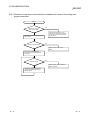
15.4 Flowchart to Use when Data Link is not Achieved ............................................................................ 15- 8
15.4.1 Flowchart to use when RUN LED is unlit .................................................................................... 15- 9
15.4.2 Flowchart to use when SD/RD LED does not turn on ................................................................ 15-10
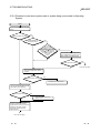
15.4.3 Flowchart to use when L.ERR. LED turns on ............................................................................. 15-11
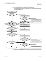
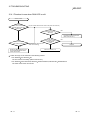
15.4.4 Flowchart to use when unable to achieve data link for entire system........................................ 15-12
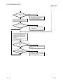
15.4.5 Flowchart to use when unable to achieve data link for specific station...................................... 15-14
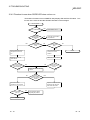
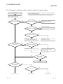
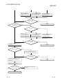
15.5 Flowchart to Use when Error Occurred During Data Link ................................................................. 15-16
15.5.1 Flowchart to use when unexpected value is input to specific link device .................................. 15-16
15.5.2 Flowchart to use when data cannot be written or read in user program.................................... 15-16
15.5.3 Flowchart to use when communication is disabled from time to time during user program
execution...................................................................................................................................... 15-17
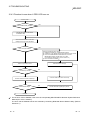
15.5.4 Flowchart to use when system reset or system hang-up occurred in Operating System ......... 15-18
15.5.5 Precautions for installing other optional board............................................................................ 15-20
15.6 When the Q80BD-J71LP21S-25’s external power supply function does not work properly............ 15-21
15.7 Measures for WDT error occurrence.................................................................................................. 15-22
15.8 Measures for Slow PC Operation....................................................................................................... 15-23
15.9 Information Needed when Calling with Inquiry .................................................................................. 15-24
APPENDIX
App- 1 to App-16
Appendix 1 Channel No. Assignment Method .........................................................................................App- 1
Appendix 2 Cautions for Accessing Redundant CPU System ................................................................App- 3
Appendix 3 Host station status at power ON/OFF when using the Q80BD-J71LP21S-25....................App- 9
Appendix 4 Warning Message Appears on Windows Vista .................................................................App-10
Appendix 4.1 Overview of warning message .......................................................................................App-10
Appendix 4.2 Methods for preventing the warning message...............................................................App-10
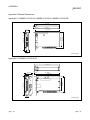
Appendix 5 External Dimensions..............................................................................................................App-15
Appendix 5.1 Q80BD-J71LP21-25, Q80BD-J71LP21G, Q80BD-J71LP21GE...................................App-15
Appendix 5.2 Q80BD-J71LP21S-25.....................................................................................................App-15
Appendix 5.3 Q80BD-J71BR11 ............................................................................................................App-16
Appendix 5.4 Q81BD-J71LP21-25 .......................................................................................................App-16
R
A - 13
A - 13
Manuals
The following table lists the manuals relevant to this product.
You can order them as necessary.
Relevant Manuals
Manual Number
(Model Code)
Manual Name
Q corresponding MELSECNET/H Network System Reference Manual (PLC to PLC network)
This manual explains the system configuration, performance specification, function, handling, wiring and
troubleshooting for MELSECNET/H network system.
(Option)
QnA/A4AR corresponding MELSECNET/10 Network System Reference Manual
This manual explains the system configuration, performance specification, function, handling, wiring and
troubleshooting for MELSECNET/10 network system.
This manual explains the system configuration, performance specification, function, handling, wiring and
A - 14
IB-66690
(13JF78)
(Option)
Type A70BDE-J71QLP23/A70BDE-J71QLP23GE/A70BDE-J71QBR13/A70BDE-J71QLR23
MELSECNET/10 Interface Board User's Manual (For SW3DNF-MNET10)
troubleshooting for MELSECNET/10 board.
SH-080049
(13JF92)
IB-0800035
(13JL93)
(Option)
A - 14
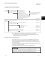
How to Use This Manual
"How to Use This Manual" differs depending on the purpose for which the
MELSECNET/H board is used. Use this manual with reference to the following
contents.
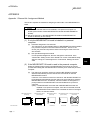
(1) When desiring an overview or to know the features of the
MELSECNET/H board (Chapter 1)
Chapter 1 gives an overview of the MELSECNET/H board and its features.
(2) When desiring to know about the system configuration
(Chapter 2)
Chapter 2 gives the system configuration.
(3) When desiring to know the specifications of the MELSECNET/H
board (Chapter 3)
Chapter 3 gives the specifications of the MELSECNET/H board.
(4) When desiring to know the functions of the MELSECNET/H board
(Chapter 4)
Chapter 4 gives the functions of the MELSECNET/H board.
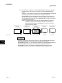
(5) When desiring to know the procedure up to the point of operation
of the MELSECNET/H board and settings (Chapter 6)
Chapter 6 gives the procedures up to the point of operation and the settings.
(6) When desiring to know the parameter settings for the
MELSECNET/H board (Chapter 7)
Chapter 7 gives the parameter settings.
(7) When desiring to know the procedure for installing and
uninstalling the software package (Chapter 8)
Chapter 8 gives the procedure for installing and uninstalling the software
package.
(8) When desiring to know the operation of each utility (Chapter 9)
Chapter 9 gives the operation methods for each utility.
(9) When desiring to know the devices which can access the
MELSECNET/H board and access ranges (Chapter 10)
Chapter 10 gives the devices which can access the MELSECNET/H board and
access ranges.
(10) When desiring to know about the MELSEC Data Link Library
(Chapter 11)
Chapter 11 gives details concerning the MELSEC Data Link Library.
A - 15
A - 15
(11) When desiring to know the interlock related signals (Chapter 12)
Chapter 12 gives the interlock related signals.
(12) When desiring to know the application functions (Chapter 13)
Chapter 13 gives the MELSECNET/H board's application functions.
(13) When desiring to know the MELSECNET/H board’s error codes
(Chapter 14)
Chapter 14 gives the error codes.
(14) When desiring to know about troubleshooting (Chapter 15)
Chapter 15 gives information on troubleshooting.
(15) When desiring to know how to assign channel No. (Appendix)
The appendix gives channel No. assignment methods for the MELSECNET/H
board.
A - 16
A - 16
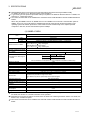
Generic Terms and Abbreviations
Unless otherwise specified, this manual uses the following generic terms and abbreviations to describe
MELSECNET/H interface board.
Generic Term/Abbreviation
Q80BD-J71LP21-25
Q80BD-J71LP21S-25
Q80BD-J71LP21G
Q80BD-J71LP21GE
Q80BD-J71BR11
Q81BD-J71LP21-25
MELSECNET/H board
MNETH utility
Personal computer
Description
Abbreviation for Q80BD-J71LP21-25 MELSECNET/H interface board.
Abbreviation for Q80BD-J71LP21S-25 MELSECNET/H interface board.
Abbreviation for Q80BD-J71LP21G MELSECNET/H interface board.
Abbreviation for Q80BD-J71LP21GE MELSECNET/H interface board.
Abbreviation for Q80BD-J71BR11 MELSECNET/H interface board.
Abbreviation for Q81BD-J71LP21-25 MELSECNET/H interface board.
Generic term for Q80BD-J71LP21-25, Q81BD-J71LP21-25, Q80BD-J71LP21S-25, Q80BDJ71LP21G, Q80BD-J71LP21GE, Q80BD-J71BR11.
Abbreviation for MELSECNET/H utility
PC/AT compatible computer
Microsoft Windows 95 Operating System (English version),
Microsoft Windows 98 Operating System (English version),
Microsoft Windows 98 Second Edition Operating System (English version),
Microsoft Windows NT Workstation 4.0 Operating System (English version),
Microsoft Windows 2000 Operating System (English version),
Microsoft Windows XP Professional Operating System (English version),
Microsoft Windows Vista Home Basic Operating System (English version),
Microsoft Windows Vista Home Premium Operating System (English version),
Microsoft Windows Vista Business Operating System (English version),
Microsoft Windows Vista Ultimate Operating System (English version),
Microsoft Windows Vista Enterprise Operating System (English version),
Microsoft Windows Server 2003 R2 Operating System (English version).
Generic term of Microsoft Windows Vista Home Basic Operating System,
Microsoft Windows Vista Home Premium Operating System,
Microsoft Windows Vista Business Operating System,
Microsoft Windows Vista Ultimate Operating System and
Microsoft Windows Vista Enterprise Operating System.
General product name for product model names SWnD5C-GPPW-E, SWnD5C-GPPW-EA,
SWnD5C-GPPW-EV, SWnD5C-GPPW-EVA.(n denotes the version number)
General product name for product model names SWnD5F-CSKP-E
(n denotes the version number)
General product name for product model names SWnD5C-ACT-E, SWnD5C-ACT-EA
(n denotes the version number)
Abbreviation for A70BDE-J71QLP23/A70BDE-J71QLP23G E/A70BDE-J71QBR13/A70BDEJ71QLR23 MELSECNET/10 interface board.
Generic term for A0J2HCPU, A1SCPU, A1SCPU-S1, A1SCPUC24-R2, A1SHCPU,
A1SJCPU, A1SJCPU-S3, A1SJHCPU, A1NCPU, A2CCPU, A2CCPUC24, A2CCPUC24PRF, A2CJCPU, A2NCPU, A2NCPU-S1, A2SCPU, A2SCPU-S1, A2SHCPU, A3NCPU,
A1FXCPU.
Generic term for A2ACPU, A2ACPU-S1, A2ACPUP21/R21, A2ACPUP21/R21-S1,
A3ACPUP21/R21, A3ACPU.
Generic term for A2UCPU, A2UCPU-S1, A2ASCPU, A2ASCPU-S1, A2ASCPU-S30,
A2USHCPU-S1, A3UCPU, A4UCPU.
Generic term for AnNCPU, AnACPU, AnUCPU.
Generic term for Q2ACPU, Q2ACPU-S1, Q2ASCPU, Q2ASCPU-S1, Q2ASHCPU,
Q2ASHCPU-S1, Q3ACPU, Q4ACPU, Q4ARCPU.
Generic term for Q02CPU-A, Q02HCPU-A and Q06HCPU-A.
R
R
R
R
R
R
R
Windows
R
R
R
R
R
R
R
R
R
R
R
R
R
R
R
R
R
R
R
Windows Vista
R
GX Developer
MX Links
MX Component
MELSECNET/10
AnNCPU
AnACPU
AnUCPU
ACPU
QnACPU
QCPU (A mode)
A - 17
R
R
R
R
R
R
R
R
R
A - 17
Generic Term/Abbreviation
MELSECNET/H
Description
Generic term for Q00JCPU, Q00UJCPU, Q00CPU, Q00UCPU, Q01CPU, Q01UCPU,
Q02CPU, Q02HCPU, Q02UCPU, Q03UDCPU, Q03UDECPU, Q04UDHCPU,
Q04UDEHCPU, Q06HCPU, Q06UDHCPU, Q06UDEHCPU, Q10UDHCPU, Q10UDEHCPU,
Q12HCPU, Q12PHCPU, Q12PHCPU, Q12PRHCPU, Q13UDHCPU, Q13UDEHCPU,
Q20UDHCPU, Q20UDEHCPU, Q25HCPU, Q25PHCPU, Q25PRHCPU, Q26UDHCPU and
Q26UDEHCPU.
Generic term for Q12PHCPU and Q25PHCPU.
Generic term for Q12PRHCPU and Q25PRHCPU.
Abbreviation for QJ71LP21, QJ71LP21G, Q71LP21GE, QJ71LP21-25, QJ71LP21S-25,
MELSECNET/H network module.
However, if shown for a particular model, QJ71LP21, QJ71LP21G, Q71LP21GE,
QJ71LP21-25, QJ71LP21S-25 is entered.
Abbreviation for QJ71BR11 MELSECNET/H network module.
Generic term for QJ71LP21, QJ71BR11
Abbreviation for Q corresponding MELSECNET/H network system.
MELSECNET/10
AnU corresponding, QnA/Q4AR corresponding MELSECNET/10 network system.
MELSECNET/H (10 Mbps)
MELSECNET/H (25 Mbps)
Abbreviation in case of using MELSECNET/H board with communication rate of 10 Mbps.
QCPU (Q mode)
Process CPU
Redundant CPU
QJ71LP21
QJ71BR11
Network module
MELSECNET/H mode
MELSECNET/H Extended
mode
MELSECNET/10 mode
A - 18
Abbreviation in case of using MELSECNET/H board with communication rate of 25 Mbps.
Abbreviation in case of using MELSECNET/H board and network module with
MELSECNET/H.
Abbreviation for the extended MELSECNET/H mode, which is extended in the maximum
number of link points per station.
Abbreviation in case of using MELSECNET/H board and network module with
MELSECNET/10.
A - 18
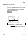
Meaning and Contents of the Terms
This section describes meaning and contents of the terms in this manual.
(1) Abbreviations for control station and normal station, and symbol format
This section explains abbreviations for control station and normal station, and
symbol format to be used in this manual.
(a) Abbreviation
Abbreviation
Name
MP
Control station
NS
Normal station (Station that can serve as a control station)
(b) Symbol format
Mp —
Group number (1 to 32) : G
Station number (1 to 64)
Abbreviation
Network No. (1 to 239)
[Example]
1) Network No. 3, control station, staiton nmber 6: 3MP6
2) Network No. 5, normal station, staiton nmber 3: 5NS3
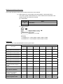
Product List
The packing list of the MELSECNET/H board is given below.
Quantity
Part name
Type Q80BD-J71LP21-25
MELSECNET/H Interface Board
Type Q81BD-J71LP21-25
MELSECNET/H Interface Board
Type Q80BD-J71LP21S-25
MELSECNET/H Interface Board
Type Q80BD-J71LP21G
MELSECNET/H Interface Board
Type Q80BD-J71LP21GE
MELSECNET/H Interface Board
Type Q80BD-J71BR11
MELSECNET/H Interface Board
Connector Set
Q80BDJ71LP21-25
Q81BDQ80BDJ71LP21-25 J71LP21S-25
Q80BDJ71LP21G
Q80BDJ71LP21GE
Q80BDJ71BR11
1
---
---
---
---
---
---
1
---
---
---
---
---
---
1
---
---
---
---
---
---
1
---
---
---
---
---
---
1
---
---
---
---
---
---
1
(for External Power Supply
Cable)
---
---
1
---
---
---
F-type Connector
---
---
---
---
---
1
1
1
1
1
1
1
1
1
1
1
1
1
Software License Agreement
1
1
1
1
1
1
Software Registration Card
1
1
1
1
1
1
MELSECNET/H Interface Board
User’s Manual (Hardware)
SW0DNC-MNETH-B
MELSECNET/H Software
Package (CD-ROM)
A - 19
A - 19
MEMO
A - 20
A - 20
1 OVERVIEW
MELSEC
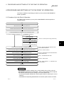
1 OVERVIEW
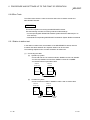
This is a manual you read when using the MELSCNET/H board in the MELSECNET/H
mode or MELSECNET/H Extended mode. When using the MELSCNET/H board in
the MELSCNET/H network, refer to "Q Corresponding MELSECNET/H Network
System Reference Manual (PLC to PLC network)". Also, when using the board in the
MELSECNET/10 network system, refer to "For QnA/Q4AR Corresponding
MELSECNET/10 network system reference manual".
1.1 Overview
The MELSECNET/H is a network system which is used to connect multiple sequencer
modules and personal computers, and is equipped with functions and performance
realized in the MELSECNET/10 for general control of a production line.
In the MELSECNET/H, there is a network system which includes an optical loop
system (communication rates: 10 Mbps, 25 Mbps) and a coaxial bus system
(communications rate: 10 Mbps), enabling large volume communications at high
speeds.
Also, in order to improve the performance of the MELSECNET/10 network and achieve
upward compatibility, MELSECNET/H supports the MELSECNET/ H and
MELSECNET/H Extended modes (high performance, high speed mode) and the
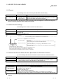
MELSECNET/10 Mode (function compatible and performance compatible mode).
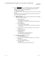
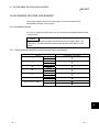
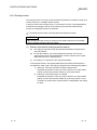
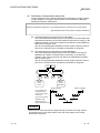
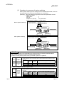
Mode
MELSECNET/H mode
Description
Set this mode when all CPUs within the network are QCPUs.
The maximum number of link points per station has been increased
MELSECNET/H Extended compared with the MELSECNET/H mode.
mode
In excess of 2000 bytes, a maximum of 35840 bytes can be set.
Set this mode when the system uses many link points per station.
MELSECNET/10 mode
Personal Computer
MELSECNET/H Board
(Q80BD-J71LP21-25)
GX Developer
This mode is used to operate the MELSECNET/H board on a
MELSECNET/10 network where the QnA/AnU exists.
QCPU 1
2
Personal Computer
MELSECNET/H Board
(Q80BD-J71BR11)
MELSECNET/10
Mode
QCPU
MELSECNET /H
MELSECNET /10
MELSECNET/H
QCPU
1
QCPU
QCPU
QCPU 1
2
QnA
QCPU
AnU
1: The multiple CPU system compatible network module is for function version B and subsequent products.
2: In the multiple CPU system, a network module that becomes a relay station is the same as the control CPU.
1-1
1-1
1
1 OVERVIEW
MELSEC
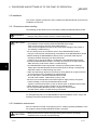
POINT
(1) For the MELSECNET/H, please select the QCPU (Q Mode) and Q compatible
network modules.
(2) If the QnACPU or ACPU are included in the same network, select the
MELSECNET/10 mode which is compatible with the MELSECNET/10.
(3) All of network modules and MELSECNET/H boards within the same network
must be set to the same mode (network type) 1.
1
1: MELSECNET/H mode, MELSECNET/H Extended mode and
MELSECNET/10 mode are available.
1.2 Features
The features of the MELSECNET/H board are as shown below.
(1) A personal computer can be incorporated into MELSECNET/H.
By mounting the MELSECNET/H board in a personal computer, the personal
computer can be used as a MELSECNET/H or MELSECNET/10 control station
or normal station.
Board model name
Q80BD-J71LP21-25
Q81BD-J71LP21-25
Q80BD-J71LP21S-25
Q80BD-J71BR11
Mode
MELSECNET/H Mode,
MELSECNET/H Extended Mode
MELSECNET/H (10 Mbps / 25 Mbps) Optical
Loop System
MELSECNET/10 Mode
MELSECNET/10 Optical Loop System
MELSECNET/H Mode,
MELSECNET/H Extended Mode
MELSECNET/H (10 Mbps) Coaxial Bus
System
MELSECNET/10 Coaxial Bus System
MELSECNET/H (10 Mbps) Optical Loop
System
MELSECNET/10 Optical Loop System
MELSECNET/10 Mode
Q80BD-J71LP21G
Q80BD-J71LP21GE
Supported network
MELSECNET/H Mode,
MELSECNET/H Extended Mode
MELSECNET/10 Mode
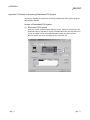
(2) Through the use of the PCI bus, it is not necessary to carry out
troublesome switch settings.
The system can be used simply by installing the MELSECNET/H board in the
personal computer, then installing the software.
The channel No., station No. and other settings can be carried out easily in the
MNETH Utility.
(3) Compatibility with the previous MELSECNET/10 board’s operations
is maintained.
(a) Upward compatibility of user programs
The MELSECNET/H board is the same as the previous MELSECNET/10
board when it comes to the maximum number of boards that can be
installed in a personal computer (No. of MELSECNET/10 boards and
MELSECNET/H boards combined) and the channel No., etc. so you can
continue to use your existing MELSECNET/10 boards.
(b) Compatible with the GX Developer, MX Links and MX
Component.
It is possible to access the programmable controller CPU using the GX
Developer, MX Links and MX Component from a personal computer where
the MELSECNET/H board is installed.
1-2
1-2
1 OVERVIEW
MELSEC
(4) Compatible with QCPU (Q Mode) multiple CPU systems.
By using logical station No. station designations in the MNETH utility, it is
possible to communicate with each CPU (Q Mode) in a multiple CPU system.
(5) Compatible with redundant CPU systems.
Only by specifying whether the destination is a control or standby station using
the user program, access is simply made without considering the current
operating system state of the redundant CPU system.
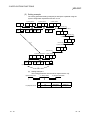
(6) Compatible with MELSECNET/H Extended mode
The MELSECNET/H Extended mode is the extended MELECNET/H mode,
which is extended in the maximum number of link points per station. With this
mode, the maximum number of link points per station can be set to 2000 bytes or
more, i.e., up to 35840 bytes.
This mode is suitable for the system that needs many number of link points per
station. However, inapplicable to the redundant CPU system.
(7) Drivers are provided for compatibility with each OS.
Each type of driver is provided, so it is easy to build a system that is compatible
with the user environment.
Compatible OS:
Microsoft Windows 95 Operating System (English Version) 1
Microsoft Windows 98 Operating System (English Version) 1
Microsoft Windows NT Workstation Operating System Version 4.0 (English Version)
R
R
R
R
R
Microsoft
Microsoft
Microsoft
Microsoft
Microsoft
Microsoft
Microsoft
Microsoft
R
R
R
R
R
R
R
R
R
Windows 2000 Professional Operating System (English Version)
Windows XP Professional Operating System (English Version)
Windows Vista Home Basic Operating System (English Version)
Windows Vista Home Premium Operating System (English Version)
Windows Vista Business Operating System (English Version)
Windows Vista Ultimate Operating System (English Version)
Windows Vista Enterprise Operating System (English Version)
Windows Server 2003 R2 Operating System (English Version)
R
R
R
R
R
R
R
R
*1: The Q81BD-J71LP21-25 is not compatible.
(8) User programming functions are provided.
Through Microsoft Visual Basic and Microsoft Visual C++ compatible
functions, it is possible to carry out remote control of a programmable controller
CPU or read and write to devices, and user programs can be created easily.
R
1-3
R
R
R
1-3
1
1 OVERVIEW
MELSEC
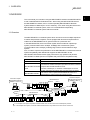
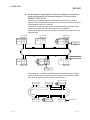
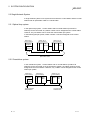
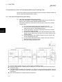
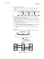
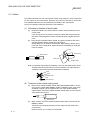
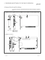
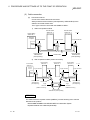
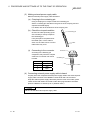
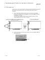
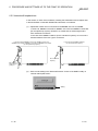
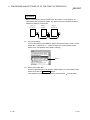
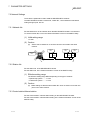
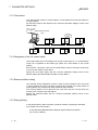
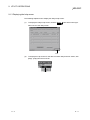
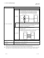
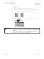
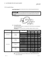
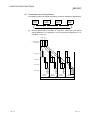
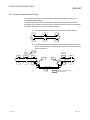
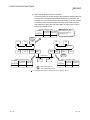
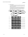
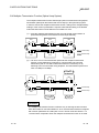
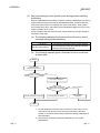
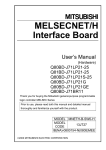
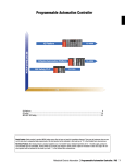
(9) External power supply allows continuous network communication
even during power-off of personal computer. (Function of the
Q80BD-J71LP21S-25)
Since power is supplied externally, the Q80BD-J71LP21S-25 can continue
network communication (baton passing) even if a personal computer is powered
off and data link cannot be performed.
Therefore, a normally operating station connected between other stations with
power-off computers will not be disconnected from the data link.
Another advantage is that the link scan time is stabilized since loopback can be
also prevented.
Control station
(Station No.1)
Personal
computer
Q80BD
-J71
LP21
-25
Normal station
(Station No.2)
Q
CPU
QJ71
LP21
-25
Normal station
(Station No.3)
Personal
computer
Q80BD
-J71
LP21S
-25
External power
supply
Data link continued
Q80BD
-J71
LP21
-25
Normal station
(Station No.6)
Personal
computer
Personal
computer
Q80BD
-J71
LP21S
-25
Normal station
(Station No.5)
Q
CPU
QJ71
LP21
-25
Normal station
(Station No.4)
External power
supply
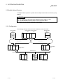
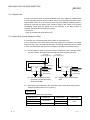
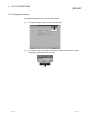
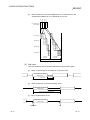
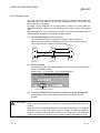
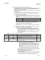
When station No. 3 and No.5 use MELSECNET/H boards without the external
power supply function and if their personal computers are powered off, station
No.4 is cut off from the network as well as No.3 and No.5.
Personal computer
Station No.1
Station No.2
Station No.3
Station No.6
Station No.5
Station No.4
Disconnected
Personal computer
1-4
1-4
1 OVERVIEW
MELSEC
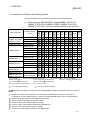
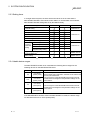
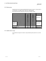
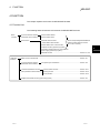
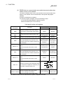
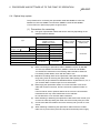
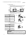
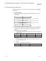
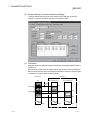
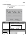
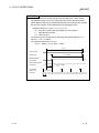
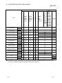
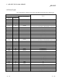
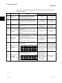
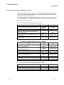
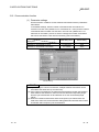
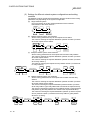
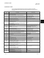
1.3 Combinations of Boards with Existing Software
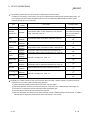
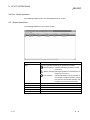
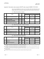
This section describes the combinations of boards with existing software.
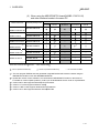
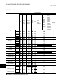
(1) When using the MELSECNET/H board(Q80BD-J71LP21-25/
Q80BD-J71LP21S-25/ Q80BD-J71BR11/ Q80BD-J71LP21G/
Q80BD-J71LP21GE) and other interface boards in the same PC
Supported OS
Board model name
A70BDE-J71QLP23
Software package
name
DOS
NT
Win
Win
Win
NT
Win
XP
XP
3.51
95
98
Me
4.0
2000
Pro
Home
Server
2003
Vista
7
6
SW0IVDWT-MNET10P
A70BDE-J71QLP23GE SW2DNF-MNET10
A70BDE-J71QBR13
SW3DNF-MNET10
A70BDE-J71QLR23
SW3DNF-MNET10
1
SW0DNF-CCLINK
1
SW1DNF-CCLINK
A80BDE-J61BT13
SW2DNF-CCLINK
SW3DNF-CCLINK
2
SW4DNF-CCLINK-B
A80BDE-J61BT11
SW3DNF-CCLINK
2
SW4DNF-CCLINK-B
SW0DNF-ANU
A80BDE-A2USH-S1
SW0DNF-ANU-B
SW1DNF-ANU-B
Q80BD-J61BT11N
SW1DNC-CCBD8-B
5
3
Q81BD-J61BT11
Q81BD-J71LP21-25
Q80BD-J71GP21-SX
Q80BD-J71GP21S-SX
SW0DNC-MNETH-B
4
SW1DNC-MNETG-B
DOS : MS-DOS 6.2
NT 3.51 : Windows NT Workstation 3.51
Win 95 : Windows 95 Win 98 : Windows 98
Win Me : Windows Me
NT 4.0 : Windows NT Workstation 4.0
Win 2000 : Windows 2000Professional
XP Pro: Windows XP Professional
XP Home : Windows XP Home Edition
Server 2003: Windows Server 2003 R2
Vista : Windows Vista
R
R
R
R
R
R
R
R
R
: Can be operated simultaneously.
R
: Cannot be operated simultaneously.
indicates an OS that is not supported by the MELSECNET/H board. It cannot be used on the same PC.
1 : Update the version of each software if it is used with the MELSECNET/H board on the same PC.
For details on version update products, contact your local Mitsubishi service center or representative.
2 : Version 40E or later supports Windows XP Professional.
3 : Version 1.04E or later supports Windows Vista .
4 : Version 1.02C or later supports Windows Vista .
5 : Version 1.06G or later supports Windows Server 2003 R2.
6 : Version 17T or later supports Windows Vista
7 : Version 19V or later supports Windows Server 2003 R2.
R
R
R
R
R
R
1-5
1-5
1 OVERVIEW
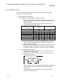
MELSEC
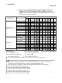
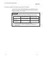
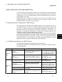
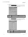
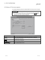
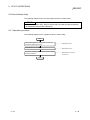
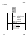
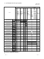
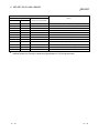
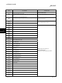
(2) When using the MELSECNET/H board(Q81BD-J71LP21-25)
and other interface boards in the same PC
Board model name
Software package name
Q80BD-J71GP21-SX
Q80BD-J71GP21S-SX
Supported OS
Win 2000
XP Pro
XP Home
—
—
Server 2003
6
Vista
SW1DNC-MNETG-B
Q80BD-J71LP21-25
SW0DNC-MNETH
Q80BD-J71BR11
SW0DNC-MNETH-B
1
—
Q80BD-J71LP21G
SW0DNC-MNETH-B
1
—
Q80BD-J71LP21S-25
SW0DNC-MNETH-B
1
—
2
Q80BD-J61BT11N
5
SW1DNC-CCBD2-B
Q81BD-J61BT11
A80BD-J61BT11
2
A80BD-J61BT13
2
A80BD-A2USH-S1
SW(0~3)DNF-CCLINK
—
—
3
SW4DNF-CCLINK-B
—
—
—
—
—
—
SW0DNF-ANU
—
—
—
—
—
SW0DNF-ANU-B
—
—
—
—
—
—
—
—
SW1DNF-ANU-B
R
Win 2000 : Windows 2000 Professional
R
Server 2003 : Windows Server 2003 R2
: Can be operated simultaneously.
R
XP Pro : Windows XP Professional
R
Vista : Windows Vista
: Cannot be operated simultaneously.
XP Home : Windows
—
R
XP Home Edition
— : No combination available
1 : The user program EXE file that was generated using MDFUNC32.LIB must be re-linked using the
MDFUNC32.LIB that comes with SW0DNC-MNETH-B.
2 : Update the version of each software if it is used with the MELSECNET/H board on the same PC.
For details on version update products, contact your local Mitsubishi service center or representative.
3 : Version 40E or later supports Windows XP Professional.
4 : Version 17T or later supports Windows Vista .
5 : Version 1.06G or later supports Windows Server 2003 R2.
6 : Version 19V or later supports Windows Server 2003 R2.
R
R
R
R
1-6
4
1-6
1 OVERVIEW
MELSEC
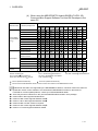
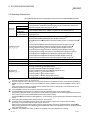
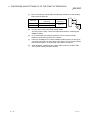
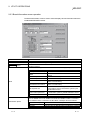
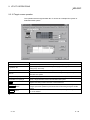
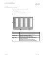
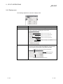
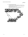
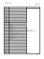
(3) When using the MELSECNET/H board (Q80BD-J71LP21-25/
Q80BD-J71LP21S-25/ Q80BD-J71BR11/ Q80BD-J71LP21G,
Q80BD-J71LP21GE),Communication Support Software Tool and
GX Developer in the same PC
Supported OS
Software name
Software package name
DOS
NT
3.51
Win
95
Win
98
Win
Me
NT 4.0
SW1D5F-CSKP-E
1
1
1
SW1D5F-CSKP-E
1
1
1
SW1D5F-OLEX-E
1
1
1
SW1D5F-XMOP-E
1
1
1
Win
2000
XP
Pro
XP Server
Home 2003
Vista
8
SW3D5F-CSKP-E
Communication Support
Software Tool 2
SW3D5F-OLEX-E
SW3D5F-XMOP-E
SW0D5C-ACT-E
SW2D5C-ACT-E
4
SW3D5C-ACT-E
5
SW1D5C-SHEET-E
SW1D5F-GPPW-E/
SW1D5C-GPPW-E
3
SW3D5F-GPPW-E/
SW3D5C-GPPW-E
SW4D5C-GPPW-E
GX Developer
SW5D5C-GPPW-E
SW6D5C-GPPW-E
SW7D5C-GPPW-E
SW8D5C-GPPW-E
GT Designer2 Version2
SW2D5C-GTD2-E
DOS : MS-DOS 6.2
NT 3.51 : Windows NT
Win Me : Windows Me
XP Pro: Windows XP Professional
Server 2003: Windows Server 2003 R2
R
R
R
7
6
R
Workstation 3.51
Win 95 : Windows 95
Win 98 : Windows 98
NT 4.0 : Windows NT Workstation 4.0
Win 2000 : Windows 2000Professional
XP Home : Windows XP Home Edition
Vista : Windows Vista
R
R
R
R
R
R
: Can be operated simultaneously.
: Cannot be operated simultaneously.
: Cannot access the MELSECNET/H board, and cannot access other stations via the MELSECNET/H board.
indicates an OS that is not supported by the MELSECNET/H board. It cannot be used on the same PC.
1 : Update the version of each software if it is used with the MELSECNET/H board on the same PC.
For details on version update products, contact your nearest Mitsubishi dealer.
2 : There may be some restrictions on the use of the MELSECNET/H board in each package.
3 : Version 30D or later supports Windows 98.
4 : Version 3.09K or later supports Windows Vista .
5 : Version 1.08J or later supports Windows Vista .
6 : Version 2.69X or a later version is required.
7 : Version 2.72A or later supports Windows Vista .
8 : Version 17T or later supports Windows Vista .
R
R
R
R
R
1-7
1-7
1 OVERVIEW
MELSEC
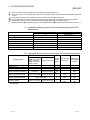
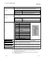
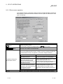
(4) When using the MELSECNET/H board (Q81BD-J71LP21-25),
Communication Support Software Tool and GX Developer in the
same PC
Supported OS
Software name
Software package name
NT
Win 95 Win 98
3.51
DOS
Win
Me
NT 4.0
SW1D5F-CSKP-E
1
1
1
SW1D5F-OLEX-E
1
1
1
SW1D5F-XMOP-E
1
1
1
Win
2000
XP
Pro
XP Server Vista
Home 2003
8
SW3D5F-CSKP-E
Communication
SW3D5F-OLEX-E
Support Software
SW3D5F-XMOP-E
2
Tool
SW0D5C-ACT-E
SW2D5C-ACT-E
SW3D5C-ACT-E
4
SW1D5C-SHEET-E
5
SW1D5F-GPPW-E/
SW1D5C-GPPW-E
3
SW3D5F-GPPW-E/
SW3D5C-GPPW-E
GX Developer
SW4D5C-GPPW-E
SW5D5C-GPPW-E
SW6D5C-GPPW-E
SW7D5C-GPPW-E
SW8D5C-GPPW-E
GT Designer2
Version2
SW2D5C-GTD2-E 6
DOS : MS-DOS 6.2
NT 3.51 : Windows NT
Win Me : Windows Me
XP Pro: Windows XP Professional
Server 2003: Windows Server 2003 R2
R
R
R
7
R
Workstation 3.51
Win 95 : Windows 95
Win 98 : Windows 98
NT 4.0 : Windows NT Workstation 4.0
Win 2000 : Windows 2000Professional
XP Home : Windows XP Home Edition
Vista : Windows Vista
R
R
R
R
R
R
: Can be operated simultaneously.
: Cannot be operated simultaneously.
: Cannot access the MELSECNET/H board, and cannot access other stations via the MELSECNET/H board.
indicates an OS that is not supported by the MELSECNET/H board. It cannot be used on the same PC.
1 : Update the version of each software if it is used with the MELSECNET/H board on the same PC.
For details on version update products, contact your nearest Mitsubishi dealer.
2 : There may be some restrictions on the use of the MELSECNET/H board in each package.
3 : Version 30D or later supports Windows 98.
4 : Version 3.09K or later supports Windows Vista .
5 : Version 1.08J or later supports Windows Vista .
6 : Version 2.69X or a later version is required.
7 : Version 2.72A or later supports Windows Vista .
8 : Version 17T or later supports Windows Vista .
R
R
R
R
R
1-8
1-8
2 SYSTEM CONFIGURATION
MELSEC
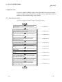
2 SYSTEM CONFIGURATION
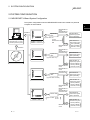
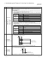
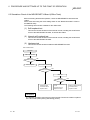
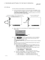
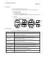
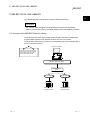
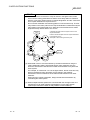
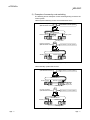
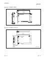
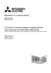
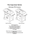
2.1 MELSECNET/H Board System Configuration
The system configuration when the MELSECNET/H board is mounted to a personal
computer is shown below.
2
Installation
Optical fiber
cable
Personal computer
equipped with 1 or more
PCI Bus (Half-size) slots.
Q80BD-J71LP21-25
Q81BD-J71LP21-25
Q80BD-J71LP21S-25
MELSECNET/H
mode,
MELSECNET/H
Extended mode
Type of cable : SI
H-PCF
Broad-band H-PCF
QSI
MELSECNET/10
mode
Installation
Optical fiber
cable
MELSECNET/H
mode,
MELSECNET/H
Extended mode
MELSECNET/H
Optical loop system
(QCPU (Q Mode))
MELSECNET/10
Optical loop system
QCPU (Q Mode)
QCPU (A Mode)
QnACPU, ACPU
MELSECNET/H
Optical loop system
(QCPU(Q Mode))
(Type of cable : GI)
Q80BD-J71LP21G
MELSECNET/10
Optical loop system
SW0DNC-MNETH-B
MELSECNET/10
mode
Optical fiber
cable
MELSECNET/H
mode,
MELSECNET/H
Extended mode
QCPU (Q Mode)
QCPU (A Mode)
QnACPU, ACPU
MELSECNET/H
Optical loop system
(QCPU(Q Mode))
(Type of cable : 62.5GI)
Q80BD-J71LP21GE
MELSECNET/10
Optical loop system
MELSECNET/10
mode
MELSECNET/H
mode,
MELSECNET/H
Extended mode
Coaxial cable
Q80BD-J71BR11
Type of cable : 3C-2V
5C-2V
MELSECNET/H
Coaxial bus system
(QCPU (Q Mode)
MELSECNET/10
Coaxial bus system
MELSECNET/10
mode
2-1
QCPU (Q Mode)
QCPU (A Mode)
QnACPU, ACPU
QCPU (Q Mode)
QCPU (A Mode)
QnACPU, ACPU
2-1
2 SYSTEM CONFIGURATION
MELSEC
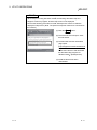
POINT
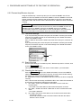
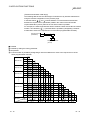
(1) When using the MELSECNET/H Extended mode
(a) Use the MELSECNET/H board of ROM version 2X or later and SW0DNCMNETH-B version 11M or later.
(b) When assigning 2000 bytes or more to the number of link points sent by a
station, set all stations including control stations and normal stations to the
MELSECNET/H Extended mode.
(2) When using the Q80BD-J71LP21S-25
Use the SW0DNC-MNETH-B version 12N or later.
(3) When using the Q80BD-J71LP21-25, Q81BD-J71LP21-25 or Q80BDJ71LP21S-25 at a communication speed of 25Mbps, errors may occur at all
stations if multiple boards with the same network number are installed, or the
operating systems are started up/shut down or the boards are reset
simultaneously on the adjacent personal computers. In this case, set the
communication speed to 10Mbps.
2
2-2
2-2
2 SYSTEM CONFIGURATION
MELSEC
2.2 Single Network System
A single network system is one system that connects the control station and the normal
stations with an optical fiber cable or a coaxial cable.
2.2.1 Optical loop system
In the optical loop system, 1 control station and 63 normal stations (a total of 64
stations) can be connected. Any station number can be assigned as the control station.
However, only one station can be set as the control station per system.
In the following sample system, station number 1 has been assigned as the control
station.
Station No. 1
(control station)
Power supply
Personal
computer
Q80BDJ71LP21-25
QCPU
Station No. 64
(normal station)
Power supply
Station No. 2
(normal station)
QJ71
LP21-25
QCPU
QJ71
LP21
Optical fiber cable
2.2.2 Coaxial bus system
In the coaxial bus system, 1 control station and 31 normal stations (a total of 32
stations) can be connected. As in the optical loop system, any station number can be
assigned as the control station. However, only 1 station can be assigned as the control
station per system.
QCPU QJ71
BR11
Station No. 32
(normal station)
Power supply
Q80BDJ71BR11
Station No. 2
(normal station)
Power supply
Station No. 1
(control station)
Personal
computer
QCPU QJ71
BR11
Coaxial cable
Terminal resistor
A6RCON-R75
2-3
Terminal resister
A6RCON-R75
2-3
2 SYSTEM CONFIGURATION
MELSEC
2.2.3 Setting items
In a single network system, the items which need to be set in the case that the
MELSECNET/H board is used as the control station or normal station are as follows.
MELSECNET/H board settings are set by the MNETH Utility.
Setting item
Control station
Normal station Reference section
Channel setting
Section 9.2.2
Network No.
Group No.
Section 9.2.3
Station No.
Control station/ Normal station
Mode Setting
Routing parameter setting
Section 9.2.4
B, W setting
Common
parameter
setting
X, Y setting
Section 9.2.5
Reserved station setting
Supplementary setting
Opposite party setting
(Logical station No.)
Section 9.2.10
Driver setting
Section 9.2.11
: Setting necessary
: Set as necessary
: Setting unnecessary
2.2.4 Usable device ranges
The MELSECNET/H board ca be used within the following device ranges for the
following devices on the MELSECNET/H board.
Device
Usable range
LB
0H to 3FFFH
(16384 points)
LW
0H to 3FFFH
(16384 points)
LX
0H to 1FFFH
(8192 points)
LY
0H to 1FFFH
(8192 points)
The function expansion areas of 2000H to 3FFFH are used for
the low-speed cyclic transmission. All areas can be used for the
normal cyclic transmission.
The use ranges for each MELSECNET/H board and network
module need to be assigned in the parameter settings for the
control station.
The use ranges for each MELSECNET/H board and network
module need to be assigned in the parameter settings for the
control station.
If the MELSECNET/H board is used in the MELSECNET/10 mode, the device range
for LB/LW becomes 0H to 1FFFH (8192 points).
2-4
2-4
2 SYSTEM CONFIGURATION
MELSEC
2.3 Multiple Network System
A multiple network system is a system where multiple networks are connected by relay
stations.
POINT
(1) The network No. can be set at any desired No. in the range 1 to 239.
(2) The MELSECNET/H board cannot be used as a relay station.
Please use the network module as a relay station.
2.3.1 Configuration
The following example shows how three networks can be connected.
Normal station Control station
1NS2
2MP1
Control station
1MP1
Power supply
Personal
computer
Q80BDJ71LP21-25
QCPU QJ71
LP21
QJ71
LP21
Q80BDJ71LP21-25
Control station
3MP1
1NS3
Normal
station
QCPU
QJ71
LP21-25 Normal station
2NS3
Power supply
Network No.3
QCPU QJ71
BR11
Q80BDJ71BR11
Personal
computer
3NS2
Normal station
2-5
Power supply
Network No.2
3NS3
Normal station
Power supply
Power supply
Network No.1
QCPU QJ71 QJ71
LP21-25 BR11
Normal station
2NS2
Personal
computer
QCPU QJ71
BR11
3NS4
Normal station
2-5
2 SYSTEM CONFIGURATION
MELSEC
2.3.2 Setting items
Setting items in the case that the MELSECNET/H board is used as a control station or
normal station in a multiple network system are explained below.
MELSECNET/H board settings are performed by the MNETH Utility.
Setting item
Channel setting
Control station
Normal station Reference section
Section 9.2.2
Network No.
Group No.
Section 9.2.3
Station No.
Control station/ Normal station
Mode setting
Routing parameter setting
Common
Parameter
Setting
Section 9.2.4
B, W setting
X, Y setting
Reserved station setting
Section 9.2.5
Supplementary setting
Opposite party setting
(Logical station No.)
Section 9.2.10
Driver setting
Section 9.2.11
2.3.3 Usable device range
The same device range as is used for a single network system (section 2.2.3) can be
used.
2-6
2-6
2 SYSTEM CONFIGURATION
MELSEC
2.4 If used in a Multiple CPU System or Redundant CPU System
For cautions in the case of installing MELSECNET/H in a multiple CPU system or
redundant CPU system, see "Q Corresponding MELSECNET/H Network System
Reference Manual (PLC to PLC network)."
POINT
When accessing a multiple CPU system or Redundant CPU system, use the
MELSECNET/H board and network module of the following function versions.
Programmable controller
MELSECNET/H board
Access to multiple
CPU system
Access to Redundant
CPU system, 2
side network module
All versions available
Function version D or later
Function version B or later
1
Function version D or later
1: When using a MELSECNET/H board of function version D or earlier,
access to a redundant CPU is not performed normally.
2: In the redundant CPU system, the MELSECNET/H Extended mode
cannot be used.
2-7
2-7
2 SYSTEM CONFIGURATION
MELSEC
2.5 Operating Environment
The following table shows the operating environment for the MELSECNET/H board.
Item
Description
Personal computer (including FC98-NX ) with one or more PCI bus slots, which meets
the specifications in "Applicable operating system and the corresponding required PC
performance" shown on the next page 1, 2, 3.
R
Personal
computer
CPU
Required memory
PCI bus
5V DC, 32-bit bus, Basic clock : 33MHz, Compliant with PCI standard Rev.2.2
specifications
PCI Express
3.3 V DC, Link width : 1lane, Basic clock : 100MHz, Compliant with PCI Express
Bus specifications standard Rev.1.0a
Microsoft Windows 95 Operating System (English version) 12
R
R
Microsoft Windows 98 Operating System (English version) 12
Microsoft Windows NT Workstation Operating System Version 4.0 (English version)
8, 12
R
R
R
R
7
Microsoft Windows 2000 Professional Operating System (English version)
R
Operating system
4, 5, 6, 11
Microsoft
Microsoft
Microsoft
Microsoft
R
R
R
R
R
7
Windows XP Professional Operating System (English version)
Windows Server 2003 R2 Operating System (English version)
Windows Vista Home Basic Operating System (English version) 7
Windows Vista Home Premium Operating System (English version)
R
R
R
R
R
R
R
R
R
R
7
7
Microsoft Windows Vista Business Operating System (English version)
Microsoft Windows Vista Ultimate Operating System (English version) 7
Microsoft Windows Vista Enterprise Operating System (English version)
Resolution: 800 600 dot or higher (Recommended: 1024 768 dot)
Display
7,
7
9
Available hard disk space
Disk drive
80MB or more
CD-ROM disk drive
Microsoft Visual Basic 5.0 (English version),
Microsoft Visual Basic 6.0 (English version),
Microsoft Visual Basic .NET 2003 (English version),
Programming
Microsoft Visual Studio 2005 Visual Basic (English version),
language 10, 11
Microsoft Visual C++ 5.0 (English version),
Microsoft Visual C++ 6.0 (English version),
Microsoft Visual C++ .NET 2003 (English version),
Microsoft Visual Studio 2005 Visual C++ (English version)
For
details
on
the
compatible
operating system and driver software version when using multiprocessor-based
1:
personal computers, refer to (2) in Section 2.5.
2: Personal computers that conform to the PCI Express standard for the Q81BD-J71LP21-25 and the PCI standard for
Q80BD-J71LP21-25, Q80BD-J71LP21S-25, Q80BD-J71LP21G , Q80BD-J71LP21GE and Q80BD-J71BR11 can be
used.
Using a personal computer not compliant with the standard may result in a problem due to a bad electrical contact,
erroneous operation or any other failures.
3: For the Q80BD-J71LP21S-25, 2 slots are required for one PCI bus.
4: The MELSECNET/H board does not support the Standby (Hibernate) mode of the operating system.
The Standby (Hibernate) mode may be preset to some personal computers so that it will be activated by pressing the
Power switch or by the UPS (Uninterruptible Power Supply system) setting.
For Windows 2000 Professional, select [Settings] – [Control Panel] – [Power Options] and disable the Standby mode
setting.
5: When exiting the operating system, always shut down the computer.
6: For details on the compatible operating system and driver software version when using the hyper-threading
technology on the personal computer, refer to (2) in Section 2.5.
When using the personal computer that includes the hyper-threading technology and Windows 95, Windows 98,
Windows NT Workstation 4.0 or Windows 2000 Professional, make sure to disable the function in the BIOS settings
of the personal computer.
7: Installation, uninstallation and usage of utilities are available only by the administrator’s authority.
R
R
R
R
R
R
R
R
R
R
R
R
R
R
R
R
R
R
R
2-8
R
R
2-8
2 SYSTEM CONFIGURATION
MELSEC
8: Service Pack3 or higher is required when using Windows NT Workstation 4.0.
9: This product does not comply with large-sized fonts when Windows 2000 Professional or Windows XP Professional
is used.
10: User programs created in the English environment work only in the English environment.
11: For the combination of operating system and programming language, refer to the Microsoft technical information.
R
R
12: The Q81BD-J71LP21-25 is not compatible with the Microsoft Windows 95 Operating System,
R
R
R
R
Microsoft Windows 98 Operating System or Microsoft Windows NT Workstation Operating System Version 4.0.
R
R
R
(1) Applicable operating system and the corresponding required PC
performance
Description
Operating system
Windows 95
Windows 98
Windows NT Workstation 4.0
Windows 2000 Professional
Windows XP Professional
Windows Server 2003 R2
Windows Vista
R
R
R
R
R
R
R
(2)
CPU
Required memory
Pentium 133MHz or higher
Pentium 133MHz or higher
Pentium 133MHz or higher
Pentium 133MHz or higher
Pentium 300MHz or higher
Pentium 550MHz or higher
800MHz or higher
32MB or more
32MB or more
32MB or more
64MB or more
128MB or more
256MB or more
512MB or more
R
R
R
R
R
R
Applicable driver versions and functions for the operating systems
SW0DNC-MNETH-B
Q80BD-J71LP21-25,
64-bit
MultiprocessorHyper-threading
Q80BD-J71LP21S-25,
Operating system
operating
based personal
technology
Q80BD-J71LP21G,
Q81BD-J71LP21-25 system
computer
Q80BD-J71LP21GE,
Q80BD-J71BR11
Windows 95
All versions
×
×
×
Windows 98
All versions
×
×
×
Windows NT Workstation 4.0
All versions
×
×
×
Version 19V or
Windows 2000 Professional
All versions
Version 19V or later
×
later
Version 11M or Version 19V or
Windows XP Professional
Version 70H or later Version 19V or later
×
later
later
Version 19V or Version 19V or
Windows Server 2003 R2
Version 19V or later
×
later
later
Version 17T or Version 19V or
Windows Vista
Version 17T or later Version 19V or later
×
later
later
R
R
R
R
R
R
R
×: Not applicable
2-9
2-9
2 SYSTEM CONFIGURATION
MELSEC
POINT
• Instruction for use of the PDF data
Use with addition of personal computer memory ensures comfortable operation.
• Note the following when using Windows XP.
The following functions cannot be used. If any of the following functions is used,
this product may not operate normally.
Start of application in Windows compatible mode
Fast user switching
Remote desktop
R
R
• Note the following when using Windows Vista .
1) The following is not supported.
Other than the default scale of 96DPI
Operating system sleep mode
2) The following functions cannot be used. If any of the following functions is
used, this product may not operate normally.
Start of application in Windows compatible mode
Fast user switching
Remote desktop
R
R
2 - 10
2 - 10
2 SYSTEM CONFIGURATION
MELSEC
2.6 Checking Versions
This section explains how to check the function version and ROM version of the
MELSECNET/H board and the SW0DNC-MNETH-B version.
(1) Checking the function/ROM version of the MELSECNET/H board
(a) Checking the MELSECNET/H board’s function version
The MELSECNET/H board’s function version can be identified at "Serial"
section on the MELSECNET/H board as shown below.
-D
Serial No.
RP
(b)
Function version
LB
Checking the MELSECNET/H board’s ROM version
The MELSECNET/H board’s ROM version is shown on "Board list" tab in
the MNETH utility.
2 - 11
2 - 11
2 SYSTEM CONFIGURATION
MELSEC
(2) Checking the SW0DNC-MNETH-B version
The SW0DNC-MNETH-B version is shown on "Version" tab in the MNETH utility.
Click!
REMARK
MELSECNET/H board’s new functions and compatible SW0DNC-MNETH-B version
MELSECNET/H board’s
ROM version
SW0DNC-MNETH-B
version
MELSECNET/H Extended mode
2X or later
11M or later
Compatibility with Hyper-Threading
technology
All versions
11M or later
New functions
2 - 12
2 - 12
3 SPECIFICATIONS
MELSEC
3 SPECIFICATIONS
This section explains the MELSECNET/H board general specifications, performance
specifications.
3.1 General Specifications
(1) This section explains the MELSECNET/H board general
specifications.
Specifications
3
Q80BD-J71LP21-25,
Q80BD-J71LP21S-25,
Q80BD-J71BR11,
Q80BD-J71LP21G,
Q80BD-J71LP21GE
Item
Q81BD-J71LP21-25
0 to 55 °C
Operating ambient temperature
-25 to 75 °C
Storage ambient temperature
Operating ambient humidity
5 to 95 % RH, No condensation
Storage ambient humidity
5 to 95 % RH, No condensation
Vibration
Resistance
Frequency
When there is Acceleration
intermittent
Amplitude
vibration
Sweep Count
Conforming
Frequency
to JIS B
When
there
is
3502(2000),
Acceleration
IEC 61132-2 continuous
Amplitude
vibration
Sweep Count
10 to 57Hz
57 to 150Hz
5 to 9Hz
9 to 150Hz
2
9.8m/s
—
9.8m/s
0.075mm
—
3.5mm
—
10 times each in X, Y and Z axis (80 minutes)
10 to 57Hz
57 to 150Hz
5 to 9Hz
9 to 150Hz
2
Operating environment
4.9m/s
—
4.9m/s
0.035mm
—
1.75mm
—
10 times each in X, Y and Z axis (80 minutes)
No corrosive gas present
Operating height
2000 m(6562 ft) or less
Installation area
On the control board
Pollution rate
2
2
—
Conforming to JIS B 3502(2000),
2
IEC 61131-2 (147 m/s , 3 times each in 3 directions)
Shock resistance
Over-voltage category
2
—
1
II or less
2 or less
1: This indicates the section of the power supply to which the equipment is assumed to be connected
between the public electrical power distribution network and the machinery within the premises. Category
II applies to equipment for which electrical power is supplied from fixed facilities. The surge voltage
withstand level for up to the rated voltage of 300 V is 2500 V.
2: This index indicates the degree to which conductive material is generated in terms of the environment in
which the equipment is used. Pollution level 2 is when only non-conductive pollution occurs. A temporary
conductivity caused by condensation must be expected occasionally.
(2) General specifications of the MELSECNET/H board or the personal
computer, whichever are lower, must be satisfied after installation.
3-1
3-1
3 SPECIFICATIONS
MELSEC
3.2 Performance Specifications
MELSECNET/H Board performance specifications are shown below.
(1) Q80BD-J71LP21-25, Q81BD-J71LP21-25,Q80BD-J71LP21S-25,
Q80BD-J71LP21G, Q80BD-J71LP21GE
Item
Specifications
Q81BD-J71LP21-25 Q80BD-J71LP21S-25 Q80BD-J71LP21G Q80BD-J71LP21GE
LX/LY
8192 Points
Maximum links
LB
16384 Points (When in the MELSECNET/10 Mode 1: 8192 Points)
in 1 network
LW
16384 Points (When in the MELSECNET/10 Mode 1: 8192 Points)
• MELSECNET/H mode, MELSECNET/10 mode 1
{(LY + LB) / 8 + (2
LW)} ≤ 2000 bytes
Maximum links in 1
station
• MELSECNET/H Extended mode 1
{(LY + LB) / 8 + (2
LW)} ≤ 35840 bytes
Communications rate 1
25 Mbps / 10 Mbps
10 Mbps
Number of stations
64 Stations (Control station: 1; Normal station: 63)
Connected to 1 network
Connection cable
Optical fiber cable
Total extension cable
30km (98430 ft.)
length
SI optical cable
: 200m (656.2 ft.)
25
H-PCF optical cable
: 400m (1312.4 ft.)
—
—
Mbps Broad-band H-PCF optical cable : 1km (3281 ft.)
Between
QSI optical cable
: 1km (3281 ft.)
stations
SI optical cable
: 500m (1640.5 ft.)
length 2
10
H-PCF optical cable
: 1km (3281 ft.)
GI optical cable
62.5 GI optical cable
Mbps Broad-band H-PCF optical cable : 1km (3281 ft.)
: 2km (6562 ft.)
: 2km (6562 ft.)
QSI optical cable
: 1km (3281 ft.)
Maximum networks
239
Maximum number of
32 (When in the MELSECNET/10 Mode: 9)
groups
Transmission channel
Duplex loop
format
Communications system
Token ring system
Synchronization system
Frame synchronization system
Encoding system
NRZI encoding (Non return to Zero inverted)
Transfer format
HDLC Standard (Frame format)
Error control system
CRC (X16 + X12 + X5 + 1) and retry by overtime.
• Loop back function (optical loop system only) by abnormal detection and cable disconnection.
• System down prevention through control station.
RAS function
• Error detection by the link special relay and link special register.
etc.
Transient transmission
N: N communications
Special cyclic
Low speed cyclic transmission
transmission
Number of boards that
Maximum 4 boards 3
can be installed
PC PCI Express
PC PCI bus slot
Installation slot
X1, X2, X4, X8, X16
PC PCI bus slot (half size)
(half size)
slot (half size)
Exclusive slots
1 slot
2 slot
1 slot
Voltage
—
20.4 to 31.2 V DC
—
Current
—
0.16 A
—
External
Connector set
power
Connector
—
—
(Accessory)
supply
2
Suitable
0.50 to 1.25 mm
—
—
cable size
[AWG20-16]
5 V DC Internal current
0.46 A
—
0.46 A
0.45 A
consumption
3.3 V DC Internal current
—
0.95 A
—
—
consumption
Weight
0.10 kg
0.20 kg
0.11 kg
Q80BD-J71LP21-25
3
3-2
3-2
3 SPECIFICATIONS
MELSEC
1: MELSECNET/H board communications rate and Mode settings are performed using the MNETH Utility.
For details, see Section 9.2.3, "Board information screen operation".
2: L type and H type of the previous optical fiber cable (A-2-
) differ in the distances between stations. For details, see
Section 6.4.1, "Optical loop system".
3: The number of boards that can be installed is the combined number of MELSECNET/H boards and MELSECNET/10
boards.
When using the Q80BD-J71LP21-25, Q81BD-J71LP21-25 or Q80BD-J71LP21S-25 at a communication speed of
25Mbps, errors may occur at all stations if multiple boards with the same network number are installed, or the
operating systems are started up/shut down or the boards are reset simultaneously on the adjacent personal
computers. In this case, set the communication speed to 10Mbps.
(2) Q80BD-J71BR11
Item
Maximum links
in 1 network
LX/LY
LB
LW
Maximum links in 1 station
Communications rate 1
Number of stations Connected
to 1 network
Connection cable
Specifications
Q80BD-J71BR11
8192 Points
16384 Points (When in the MELSECNET/10 Mode
16384 Points (When in the MELSECNET/10 Mode
• MELSECNET/H mode, MELSECNET/10 mode 1
{(LY + LB) / 8 + (2
LW)} ≤ 2000 bytes
• MELSECNET/H Extended mode 1
{(LY + LB) / 8 + (2
LW)} ≤ 35840 bytes
10 Mbps
Maximum networks
Maximum number of groups
Transmission channel format
Communications system
Synchronization system
Encoding system
Transfer format
Error control system
RAS function
Transient transmission
Special cyclic transmission
Number of boards that can be
installed
Installation slot
Exclusive slots
5 V DC Internal current
consumption
Weight
: 8192 Points)
: 8192 Points)
1
32 Stations (Control station: 1; normal station: 31)
Optical fiber cable
Cable name
Total extension cable length in
1 network
1
Coaxial cable
Total extension
cable length
Length between
stations
3C-2V
300 m (Between stations: 300 m)
2
5C-2V
500 m (Between stations: 500 m)
2
Can be extended to 2.5 km (8202.5 ft.) using a repeater unit (A6BR10, A6BR10-DC).
239
32 (When in the MELSECNET/10 Mode: 9)
Single Bus
Token bus system
Frame synchronization system
NRZI encoding (Non return to Zero inverted)
Manchester encoding
HDLC Standard (Frame format)
CRC (X16 + X12 + X5 + 1) and retry by overtime.
• Loop back function (optical loop system only) by abnormal detection and cable disconnection.
• System down prevention through control station.
• Error detection by the link special relay and link special register.
etc.
N:N communications
Low speed cyclic transmission
Maximum 4 boards
3
PC PCI bus slot (half size)
1 slot
0.67 A
0.11 kg
1: MELSECNET/H board communications rate and Mode settings are performed using the MNETH Utility.
For details, see Section 9.2.3, "Board information screen operation".
2: Depending on the number of stations connected, there are limits to the cable length between stations. For details, see
section 6.4.2, "Coaxial bus system".
3: The number of boards that can be installed is the combined number of MELSECNET/H boards and MELSECNET/10
boards.
3-3
3-3
3 SPECIFICATIONS
MELSEC
3.3 Optical Fiber Cable Specification
For the optical fiber cable specification, see "Q corresponding MELSECNET/H network
system reference manual (PLC to PLC network)".
3.4 Coaxial Cable Specification
For the coaxial cable specification, see "Q corresponding MELSECNET/H network
system reference manual (PLC to PLC network)".
3-4
3-4
4
FUNCTION
MELSEC
4 FUNCTION
This chapter explains the function of MELSECNET/H board.
4.1 Function List
The following flowchart shows the function list for MELSECNET/H board.
Basic
functions
Cyclic transmission function
(Periodical communication)
Communication LB/LW
RAS function
Automatic return function
Communication LX/LY
Control station switch function
Control station return control function
See Q corresponding MELSECNET/H
network system reference manual
(PLC to PLC network)
Loopback function (optical loop system)
4
Prevention of station failure by using external
power supply (optical loop system)
Diatnostic function ········································································· Section 6.5, 6.6
Application
functions
Direct access to link devices ················································································································ Section 13.1
Cyclic transmission function
(Periodical communication)
Transient transmission function
(Non-periodical communication)
Low-speed cyclic transmission ······················································· Section 13.2
Communication function ··························································· Section 13.3.1
Routing function ······································································· Section 13.3.2
Group function ········································································· Section 13.3.3
Multiple transmission function (optical loop system) ··········································································· Section 13.4
4-1
4-1
4
FUNCTION
MELSEC
4.2 Specifications of the Link Data Sending/Receiving Processing Time
This section explains the link data sending/receiving processing in the MELSECNET/H
network system with MELSECNET/H board.
4.2.1 Link data sending/receiving processing
(1) Link data sending/receiving processing
In the cyclic transmission, communication is performed using the LB/LW/LX/LY
devices of the network module and MELSECNET/H board.
This section explains the case when the link relay (B) is used on the personal
computer side.
1)
2)
3)
4
4)
5)
6)
7)
B0 on the sending station (personal computer) turns on.
By a link refresh, the B0 information is stored in the refresh data
storage area (LB) of the MELSECNET/H board.
The B0 information in the refresh data storage area (LB) is stored in
the link data storage area (LB).
By a link scan, the B0 information in the link data storage area (LB) is
stored in the link data storage area (LB) of the network module on the
receiving station.
The B0 information in the link data storage area (LB) is stored in the
refresh data storage area (LB).
By a link refresh, the B0 information is stored in the device memory
storage area (B) of the CPU module.
B0 on the receiving station turns on.
1: The link refresh interval is set on the "Driver" screen in the MNETH Utility.
2: Set by the GX Developer’s "Station Inherent Parameters." (If not set, they are stored in the common
parameters state.)
3: If the MELSECNET/H board is a control station, it is set in the "Common Parameter Setting" screen in
the MNETH Utility. If the network module is a control station, it is set in the GX Developer’s "Common
Parameters."
4: Set in the GX Developer’s "Network Refresh Parameters."
4-2
4-2
4
FUNCTION
MELSEC
(2) Link scan and link refresh
The link scan is executed "asynchronous" with the sequence scan of the CPU
module.
The link refresh is executed by the "END processing" of the CPU module.
Sequence scan
0
0
END
END
Link refresh
0
END
Link refresh
0
END
Link refresh
Link scan
(3) Link data when a communication error station or communication
stop station occurs on the network
When a communication error or communication stop station occur on the network
during the data link, the receive data from those stations immediately before the
error occurrence is retained.
(A "communication stop station" refers to a station whose cyclic transmission has
been stopped by a peripheral device.)
(a)
The receive data from a communication error station or communication stop
station is retained by a normally communicating station.
(b)
The receive data from other station is retained by a communication stop
station.
(Example)
When a communication error has occurred to 1NS2 due to cable disconnection
Cable disconnection
1MP1
Communication
error station
1NS2
1NS3
Cable disconnection
Link data status after disconnection
1MP1
1NS2
1NS3
Link data
Link data
Link data
1MP1
1MP1
1MP1
1NS2
1NS2
1NS2
1NS3
1NS3
1NS3
· · · · · · Area where the link data is retained
4-3
4-3
4
FUNCTION
MELSEC
(4) SB/SW when a communication error station/communication stop
station occurs on the network
The status of whether there are any communication error/communication stop
stations on the network can be checked with the link special relay/register
(SB/SW).
Use them as interlocks for programs.
For interlock program examples, refer to the following manual.
Q Corresponding MELSECNET/H Network System
Reference Manual (PLC to PLC network)
Link special relays and registers
Link special
Description
relay/register
Signal status
Off
On
Normal
Abnormal
The baton pass is
The baton pass is
being executed
stopped
Normal
Abnormal
The baton pass is
Occurrence of
being executed on
communication
all stations
stop station
The baton pass is
The baton pass is
being executed
stopped
Indicates the operation status of the network
SB20
module and the communication status with the
CPU.
SB47
SB49
Shows the baton pass execution status of the
host.
Shows the cyclic transmission status of the host.
Shows the baton pass execution status of all
SB70
stations (including the host). However, it only
shows the status for the number of stations set
with parameters.
Shows the baton pass execution status of each
SW70 to 73
station.
Each bit corresponds to the status of each
station.
Shows the cyclic transmission status of all
SB74
stations (including the host). However, it only
shows the status for the number of stations set
All stations
Occurrence of
normal
abnormal station
Normal
Abnormal
with parameters.
Shows the cyclic transmission status of each
SW74 to 77
station.
Each bit corresponds to the status of each
station.
SB7A
Shows the low-speed cyclic transmission status.
SB7A, 7B
The transmission completion is indicated by the
SB7B
on/off status of either bit SB7A or 7B.
Low-speed cyclic interval
Shows the redundant CPU system status
SW1FC to SW1FF (Control or Standby) of each station.
Control system
1
Standby system
Each bit corresponds to each station status.
1: Stations in other than the redundant CPU system configuration are OFF.
4-4
4-4
5 EMC AND LOW VOLTAGE DIRECTIVE
MELSEC
5 EMC AND LOW VOLTAGE DIRECTIVE
For the products sold in European countries, the conformance to the EMC Directive,
which is one of the European Directives, has been a legal obligation since 1996. Also,
conformance to the Low Voltage Directive, another European Directive, has been a
legal obligation since 1997.
Manufacturers who recognize their products must conform to the EMC and Low
Voltage Directives are required to declare that their products conform to these
Directives and put a "CE mark" on their products.
5.1 Requirements for Conformance to EMC Directive
The EMC Directive specifies that products placed on the market must "be so
constructed that they do not cause excessive electromagnetic interference (emissions)
and are not unduly affected by electromagnetic interference (immunity)". The
applicable products are requested to meet these requirements. The sections 5.1.1
through 5.1.5 summarize the precautions on conformance to the EMC Directive of the
machinery constructed using the MELSECNET/H board.
The details of these precautions has been prepared based on the control requirements
and the applicable standards . However, we will not assure that the overall machinery
manufactured according to these details conforms to the above-mentioned directives.
The final decision on the method for the EMC Directive conformance and the
application must be made by the manufacturer of the machinery.
5.1.1 Standards applicable to the EMC Directive
The standards applicable to the EMC Directive are listed below.
All test items were tested by installing each device on a personal computer bearing a
CE certification logo.
Specification
Test item
Test details
EN55011
Radiated noise
Electromagnetic emissions from the
product are measured.
EN55011
Conducted noise
Electromagnetic emissions from the
product to the power line is measured.
EN50081-2 :
1995
Standard value
30M-230MHz QP : 30dB µ V/m
(30 m in measurement range)
230M-1000MHz QP : 37 dB µ V/m
(30 m in measurement range)
150k-500kHz QP: 79 dB,
Mean: 66 dB 1
500k-30MHz QP: 73 dB,
Mean: 60 dB
EN61000-4-2
Electrostatic immunity
Immunity test in which static electricity is
15kV Aerial discharge
applied to the cabinet of the equipment.
Power line: 2kV
Immunity test in which burst noise is
Digital I/O (24V or higher): 1kV
EN61000-4-4
applied to the power line and signal
(Digital I/O (24V or less)) > 250V
Fast transient burst noise
EN61131-2 :
lines.
(Analog I/O, signal lines) > 250V
1996
EN61000-4-3
Immunity test in which field is irradiated 10V/m, 26-1000MHz,
Radiated field AM modulation to the product.
80%AM modulation@1kHz
Immunity test in which a damped
EN61000-4-12
Power line: 1kV
oscillatory wave is superimposed on the
Damped oscillatory wave
Digital I/O (24V or higher): 1kV
power line.
immunity
1 : QP : Quasi-peak value, Mean : Mean value
5-1
1
5-1
5
5 EMC AND LOW VOLTAGE DIRECTIVE
MELSEC
5.1.2 Installing devices in the control panel
Installing devices in the control panel has a considerable effect, not only securing
safety but also shielding the noise generated from the personal computer in the control
panel.
(1) Control panel
(a)
Use a conductive control panel.
(b)
When attaching the control panel's top plate or base plate, mask painting
and weld so that good surface contact can be made between the panel and
plate.
(c)
To ensure good electrical contact with the control panel, mask the paint on
the installation bolts of the inner plate in the control panel so that contact
between surfaces can be ensured over the widest possible area.
(d)
Ground the control panel with a thick wire so that a low impedance
connection to ground can be ensured even at high frequencies.
(e)
Holes made in the control panel must be 10 cm (3.94 in.) diameter or less.
If the holes are 10 cm (3.94 in.) or larger, radio frequency noise may be
emitted.
In addition, because radio waves leak through a clearance between the
control panel door and the main unit, reduce the clearance as much as
practicable. The leakage of radio waves can be suppressed by the direct
application of an EMI gasket on the paint surface.
5
Maker name
KITAGAWA INDUSTRIES CO., LTD.
ZIPPERTUBING (JAPAN) LTD.
SEIWA ELECTRIC MFG CO., LTD.
Series type
US series
71TS series
E02S
A
Our tests have been carried out on a panel having the damping
characteristics of 37 dB max. and 30 dB mean (measured by 3 m method
with 30 to 300 MHz).
(2) Connection of power and ground cable
The power supply cable and ground cable for a personal computer should be laid
out as follows:
5-2
(a)
Provide a grounding point near the power supply of personal computer.
Ground the FG (frame ground) terminal of the personal computer and the
SLD (shield) terminal of the MELSECNET/H board with the thickest and
shortest grounding wire (wire for grounding) possible (about 30 cm (11.81
in.) or less in length). Since the FG and SLD terminals function to ground
the noise generated in the personal computer, it is necessary to ensure the
lowest possible impedance.
As the wires are used to relieve the noise, the wire itself contains a large
amount of noise and thus short wiring prevents from functioning as an
antenna.
(b)
Twist the ground cable leading to the ground point with the power supply
cable. By twisting it with the ground cable, the noise leaking from the power
supply cable may be grounded at a higher rate. However, twisting the
power supply cable with the ground cable may not be necessary if a noise
filter is installed on the power supply cable.
5-2
EMC AND LOW VOLTAGE DIRECTIVE
MELSEC
5.1.3 Cables
The cables extracted from the control panel contain a high frequency noise component.
On the outside of the control panel, therefore, they serve as antennas to emit noise.
Use shielded cable for the to be extracted to the outside of the control panel.
The use of a shielded cable also increases noise resistance.
(1) Grounding of shielded of shield cable
(a)
Ground the shield of the shield cable as near the exit as possible from the
control panel.
If the ground point is not near the outlet, the cables after the ground point
will cause electromagnetic induction, and will generate a higher harmonic
noise.
(b)
Peel part of the shielded cable's sheath, and ground a wide section of the
exposed shielded section against the control panel.
Clamp fittings can be used as shown below. Note that the painting on the
inner side of the control panel, against which the clamp fitting is contacted,
must be masked.
Screw
Clamp fitting
Shield section
Paint mask
Shielded cable
Note) The method of grounding by soldering a wire onto the shield section of the
shielded cable as shown below is not recommended. The high frequency
impedance will increase and the shield will be ineffective.
Shielded cable
Wire
Crimp terminal
(2) Treatment of the coaxial cable ground
(a)
Always use a double-shielded coaxial cable (MITSUBISHI CABLE : 5C-2VCCY) for the coaxial cables Q80BD-J71BR11. Radiated noise in the range
of 30MHz or higher can be suppressed by use of the double-shielded
coaxial cables. Ground the double-shielded coaxial cable by connecting its
outer shield to the ground.
Ground here.
(b)
5-3
Attach a ferrite core to the double-shielded coaxial cable connected to the
Q80BD-J71BR11.
The ferrite core should be attached on each cable near the outlet of the
control panel.
Refer to section "5.1.4 Ferrite core" for details.
5-3
EMC AND LOW VOLTAGE DIRECTIVE
MELSEC
5.1.4 Ferrite core
A ferrite core has the effect of reducing radiated noise in the 30MHz to 100MHz band.
It is not required to fit ferrite cores to cables, but it is recommended to fit ferrite cores if
shield cables pulled out of the enclosure do not provide sufficient shielding effects. It
should be noted that the ferrite cores should be fitted to the cables in the position
immediately before they are pulled out of the enclosure. If the fitting position is
improper, the ferrite will not produce any effect.
y Ferrite core
Type: ZCAT3035-1330 (TDK ferrite core)
5.1.5 Noise filter (power supply line filter)
A noise filter is a component which has an effect on conducted noise.
It is not required to fit the noise filter to the power supply line, but fitting it can further
suppress noise. (The noise filter has the effect of reducing conducted noise of 10MHz
or less.) The precautions required when installing a noise filter are described below.
(1)
Do not bundle the wires on the input side and output side of the noise filter. When
they are bundled, the output side noise will induct into the input side wires.
Input side
(power supply side)
Input side
(power supply side)
Introduction
Filter
Filter
Output side
Output side
(device side)
(device side)
(a) The noise will induct into input
side when the input and output
wires are bundled.
(2)
(b) Separate the input and output
wires.
Ground the ground terminal of the noise filter to the control panel using as short
wiring as possible (about 10 cm (3.94 in.)).
REMARK
Reference noise filters are shown below.
Noise filter type
FN343-3/01
FN660-6-06
ZHC2203-11
5-4
Maker name
SCHAFFNER
TDK
Rated current
Rated voltage
3A
6A
250V
3A
5-4
EMC AND LOW VOLTAGE DIRECTIVE
MELSEC
5.2 Requirements for Conformance to Low Voltage Directive
The MELSECNET/H board is out of the requirement for conformance to the Low
Voltage Directive, since it does not use the power supply in the range of 50 to 1000V
AC and 75 to 1500V DC.
5-5
5-5
EMC AND LOW VOLTAGE DIRECTIVE
MELSEC
MEMO
5-6
5-6
6 PROCEDURE AND SETTINGS UP TO THE POINT OF OPERATION
MELSEC
6 PROCEDURE AND SETTINGS UP TO THE POINT OF OPERATION
This section explains the operating procedure up to the point the MELSECNET/H
board is operated.
6.1 Procedure Up to the Point of Operation
An outline of the procedure up to the point of MELSECNET/H board operation is
explained below.
Start
When the PC is powered on, power off it.
Install the MELSECNET/H board to the PCI bus slot of the PC.
Fix the MELSECNET/H board with the PC's board fixing screws.
For other than Q80BD-J71LP21S-25
For Q80BD-J71LP21S-25
Make an external
power supply cable.
········See 6.4.4, External power supply cable wiring
Connect the external power supply
cable to the Q80BD-J71LP21S-25.
6
Turn on the external power supply.
Power off the PC and install the SW0DNC-MNETH-B.
Perform the wiring between the MELSECNET/H board and each station.
Perform standalone check of MElSECNET/H board.
········See 8, "INSTALLING AND UNINSTALLING
SOFTWARE PACKAGE."
········See 6.4 "Cable connection".
········See 6.5 "Standardalone check MELSECNET/H
board (Offline tests)
Perform parameter setting for MELSECNET/H.
·······See 7, "PARAMETER SETTING"
Perform offline tests of MELSECNET/H board.
·······See 6.6, "Offline Tests"
Execute user program or each utiility.
······See 9, "Utility Operation", 11, "MELSEC DATA
LINK LIBRARY"
Complete
REMARK
It is necessary to perform settings on the control station side in order to use the
MELSECNET/H board as a normal station. Set the control station side as required.
See manuals listed below for the setting on the control station side.
• Q corresponding MELSECNET/H network system reference manual (PLC to PLC
network)
• QnA/Q4AR Corresponding MELSECNET/10 network system reference manual
6-1
6-1
6 PROCEDURE AND SETTINGS UP TO THE POINT OF OPERATION
MELSEC
6.2 Installation
This section explains precautions when handling the MELSECNET/H board and the
installation environment.
6.2.1 Precautions when handling
The following are precautions to be noted when handling the MELSECNET/H board.
DANGER
• While energizing, do not touch the connector.
Doing so may result in electric shock or cause malfunctioning.
CAUTION
• Fasten the MELSECNET/H board securely using the installation screws and tighten
the installation screws securely within the specified torque range.
If the screws are loose, this may cause malfunctioning.
If the screws are tightened too much, this could cause damage to the screws or
unit, leading to malfunctioning.
• Do not directly touch the conductive section of the MELSECNET/H board.
Doing so could result in malfunctioning or breakdown of the MELSECNET/H board.
• Before handling the MELSECNET/H board, touch a grounded metal object to
discharge the static electricity from the human body.
Failure to do so may cause failure or malfunction of the MELSECNET/H board.
• Handle the MELSECNET/H board in a location where there is no static electricity.
Static electricity could result in failure or malfunctioning.
• The MELSECNET/H board is packed in a bag for preventing static electricity.
Always place the MELSECNET/H board in this bag when storing or transporting.
Otherwise, failure or malfunctioning may result.
• Take care that foreign objects such as chips or wiring debris do not get into the PC.
This could result in fire, breakdowns or malfunctioning.
• Do not dismantle or rebuild the MELSECNET/H board.
This will result in failure, malfunctioning, injury or fire.
• Be sure to shut off all phases of the external power supply used by the system
before installing or removing the MELSECNET/H board.
If power is not turned off, there is a risk of electric shock or damage to the product.
• When disposing of the product, handle it as an industrial waste.
• Do not drop the MELSECNET/H board or subject it to strong impact.
This will result in failure or malfunctioning of the board.
6
For the tightening torque of the MELSECNET/H board installation screws, refer to the
handling instructions supplied with the personal computer.
6.2.2 Installation environment
See the instruction manual accompanying the PC module regarding installation of the
PC module in which the MELSECNET/H board is mounted.
CAUTION
6-2
• Always ground the PC module using grounding type D (Class 3 grounding).
Otherwise, there is the risk of malfunctioning.
6-2
6 PROCEDURE AND SETTINGS UP TO THE POINT OF OPERATION
MELSEC
6.3 Names of Each Part and Their Settings
The names of each part of the MELSECNET/H board and their settings are explained
below.
(1) Q80BD-J71LP21-25, Q81BD-J71LP21-25, Q80BD-J71LP21G, Q80BD-J71LP21GE, Q80BD-J71BR11
1)
4)
L
RUN ERR.
SD
L
RUN ERR.
SD
RD
RD
IN
3)
2)
OUT
Q80BD-J71BR11
Q80BD-J71LP21-25
Q81BD-J71LP21-25
Q80BD-J71LP21G
Q80BD-J71LP21GE
(2) Q80BD-J71LP21S-25
1)
4)
5)
L
RUN ERR.
EXT.PW
SD RD
IN
6)
EXT.PW
CLASS2 ONLY
2)
7)
OUT
+24V
24G
NC
6-3
6-3
6 PROCEDURE AND SETTINGS UP TO THE POINT OF OPERATION
No.
Name
MELSEC
Description
Shows the MELSECNET/H board's operating state.
When the LED is lighted up, there are two display formats, one for the normal mode and the
other for the error mode.
(1) Normal Mode
In the normal mode, if a communications error occurs, judge that it is an error from the LED
state in the MELSECNET/H utility "Board Information."
As for the LED state in the "Board Information" screen, see Section 9.2.3, "Board information
screen operations."
LED name
RUN.
Indicator LED
1)
L
RUN ERR.
SD
RD
L.ERR
SD
RD
Status
Off
Lighted up
Off
Lighted up
Off
Lighted up
Off
Lighted up
Description
A WDT error has occurred, or the board is being reset.
Operating normally.
A communications error has not occurred.
A communications error has occurred.
Data not transmitted.
Data are being transmitted.
Data not received.
Data are being received.
(2) Error mode
When the RUN LED is blinking, the LED display format is the error mode.
In the error mode, is an error occurs, confirm the content of the error using the error viewer
or the event viewer.
For details, see Section 9.4, "Error Viewer Operation."
LED name
RUN.
L.ERR
SD
RD
Status
Blinking
Off
Lighted up
Off
Lighted up
Off
Lighted up
Off
Lighted up
Description
Shows that it is in the error mode.
No error
An OS starting error has not occurred.
An OS starting error has occurred.
A driver response error has not occurred.
A driver response error has occurred.
A PCI bus error has not occurred.
A PCI bus error has occurred.
Connector for connecting optical fiber cable.
(1) The cable terminal is as shown below.
L
RUN ERR.
LED
SD
RD
IN
2)
Connector for
connecting
optical fiber cable
IN
Reverse loop transmission
IN
Forward loop reception
Optical fiber cable
connection connector
OUT
OUT Forward loop transmission
OUT Reverse loop reception
(2) See Section 6.4, "Cable Connections." for wiring of the optical fiber cable.
Connector for connecting coaxial cable.
(1) The cable terminal is as shown below.
3)
Connector for
connecting
coaxial cable
L
RUN ERR.
LED
SD RD
Coaxial cable
connection connector
(2) See Section 6.4, "Cable Connections." for wiring of the coaxial cable.
6-4
6-4
6 PROCEDURE AND SETTINGS UP TO THE POINT OF OPERATION
No.
Name
Jumper
4)
MELSEC
Description
1
RP
LB
Use prohibited (Fixed to RP side)
DIP switch
Use prohibited (Fixed to OFF)
5)
The external power supply status is indicated.
6)
External power
supply indicator
LED
LED name
EXT.PW
Status
Unlit
Lit
Description
No external power supplied
External power supplied
Connector for connecting external power supply cable
The cable terminal assignment is as shown below.
EXT.PW
7)
External power
supply cable
connector
(With the board top facing up)
EXT.PW
CLASS2 ONLY
24V
24G
1: The jumper is provided for all of the Q80BD-J71LP21S-25, Q81BD-J71LP21-25, and the Q80BD-J71LP21-25 and
Q80BD-J71LP21G of the following serial No.
Q80BD-J71LP21-25:
The sixth digit (from the left) of the serial No. is 7 or higher.
7
-
Serial No. (Check the "Serial" field.)
RP
LB
Q80BD-J71LP21G, Q80BD-J71LP21GE:
The sixth digit (from the left) of the serial No. is 4 or higher.
4
-
The serial No. of the board can be verified at the part shown
in the illustration.
6-5
6-5
6 PROCEDURE AND SETTINGS UP TO THE POINT OF OPERATION
MELSEC
6.4 Cable Connection
This section explains precautions when connecting cables to MELSECNET/H board.
(1) Precautions on general wiring
DANGER
• Be sure to shut off all phases of the external power supply used by the system
before performing work such as installing the MELSECNET/H board and wiring.
If all power is not turned off, there is a risk of electric shock or damage to the
product.
• When turning on the power and operating the module after having installed the
MELSECNET/H board and doing the wiring, always attach the cover for the device
module in which the MELSECNET/H board is installed.
There is a risk of electric shock if the module cover is not attached.
CAUTION
• When removing the cable from the MELSECNET/H board, do not pull the cable.
Pulling the cable that is still connected to the MELSECNET/H board may cause
damage to the MELSECNET/H board or cable, or malfunction due to bad cable
contacts.
• Prevent foreign matter such as chips or wiring debris from getting on the
MELSECNET/H board.
Failure to do so can result in fire, breakdowns or malfunction.
(2) Precautions on communication cable wiring
CAUTION
• Solder the coaxial cable properly.
If the soldering is incomplete, it may cause the module malfunction.
• For the communication cable, specialized skills and tools are required to connect
the plug and cable. The connector plug itself is a custom part.
When purchasing, consult your local Mitsubishi representative.
If the connection is incomplete, this can result in a short, fire or malfunction.
• Be sure to fix communication cables connecting to the MELSECNET/H board by
placing them in the duct or clamping them.
Cables not placed in the duct or without clamping may be hang freely and
accidentally pulled, which may cause damage to the MELSECNET/H board or
cable, or malfunction due to bad cable contacts.
REMARK
See "Q corresponding MELSECNET/H reference manual (PLC to PLC network) for
details of each communication cable.
6-6
6-6
6 PROCEDURE AND SETTINGS UP TO THE POINT OF OPERATION
MELSEC
(3) Precautions on external power supply cable wiring
CAUTION
6-7
• Verify the rated voltage and pin assignment of the product and connect the external
power supply cable properly.
Connecting a power supply with a different voltage rating, imperfect cable crimping
or faulty wiring may cause a fire or failure.
• Use a specified tool for crimping of the cable and contacting pin. Imperfect crimping
may cause malfunction.
• Verify the pin assignment and fully insert the crimped contacting pin into the
connector. Imperfect insertion may cause failure or malfunction.
• Insert the wired external power supply cable into the external power supply cable
connector until a click is heard. Imperfect insertion may cause failure or
malfunction.
• Keep the external power supply cable away from the main circuit cable, power
cables and/or load cables connected to other than programmable controllers.
Ensure a distance of 100mm between them. Failure to do so may result in
malfunction due to noise, surge or induction.
6-7
6 PROCEDURE AND SETTINGS UP TO THE POINT OF OPERATION
MELSEC
6.4.1 Optical loop system
The precautions for connecting the optical fiber cable with Q80BD-J71LP21-25,
Q81BD-J71LP21-25, Q80BD-J71LP21S-25, Q80BD-J71LP21G and Q80BDJ71LP21GE in an optical loop system are given below.
(1) Precautions for connecting
(a)
The types of optical fiber cables that can be used vary depending on the
distance between stations.
Distance between stations (m)
Q80BD-J71LP21-25,
Type
SI type optical fiber cable
(Old type: A-2P- )
Q81BD-J71LP21-25,
Q80BD-J71LP21S-25
L type
H type
10Mbps
25Mbps
500 (1640.5 ft.)
200 (656.2 ft.)
300 (984.3 ft.)
100 (328.1 ft.)
SI optical fiber cable
500 (1640.5 ft.)
200 (656.2 ft.)
H-PCF optical fiber cable
1000 (3281 ft.)
400 (1312.4 ft.)
Broad-band H-PCF optical fiber cable
1000 (3281 ft.)
1000 (3281 ft.)
QSI optical fiber cable
1000 (3281 ft.)
1000 (3281 ft.)
Not allowed
Not allowed
GI optical fiber cable
62.5 GI optical fiber cable
(b)
(c)
(d)
(e)
(f)
(g)
6-8
Q80BD-J71LP21G
10Mbps (fixed)
Not allowed
Q80BD-J71LP21GE
10Mbps (fixed)
Not allowed
2000 (6562 ft.)
Not allowed
2000 (6562 ft.)
When connecting an optical fiber cable to Q80BD-J71LP21-25, Q81BDJ71LP21-25, Q80BD-J71LP21S-25, Q80BD-J71LP21G and Q80BDJ71LP21GE the restrictions on the bending radius should be observed.
For bending radius details, check with the cable to use.
Maintain the bending radius of the optical fiber cable within the allowable
range using a tool for securing the optical fiber cable bending radius.
This tool may be purchased from Mitsubishi Electric System Service, Inc, or
your nearest dealer. Please inquire for more information.
When laying the optical-fiber cables, do not touch the fiber cores of the
cable and module connectors, and do not let dust or particles collect on
them.
If oil from hands, dust or particles adhere to the cores, the accumulated
transmission loss may cause malfunctions in the data link.
Do not detach the cover until the cable is attached.
When attaching or detaching the optical fiber cable to/from the module, pull
or insert the cable by holding the cable connector securely with your hand.
Connect the cable and module connectors securely until you hear a "click"
sound.
When attaching or detaching the optical fiber cable to/from the module,
make sure to power off the personal computer and external power supply.
6-8
6 PROCEDURE AND SETTINGS UP TO THE POINT OF OPERATION
MELSEC
(2) Cable connection
How to connect the cable
Connect the IN and OUT terminals with optical fiber cables as shown below.
Stations do not have to be connected in the order of station numbers.
Any station number can be assigned as the control station.
Control station
Normal station
Station
No. 2
Personal
computer
Q80BDJ71LP21-25
IN
(b)
Power supply
Station
No. 1
QCPU QJ71
LP21
-25
OUT
IN
Normal station
Station
No. n
Power supply
(a)
n ≤ 64
QCPU QJ71
LP21
-25
OUT
IN
OUT
Installing the optical fiber cable
The following shows how to install the optical fiber cable:
Jack
Start (Installation)
Power off the personal computer and external power
supply.
Insert the plug by aligning the groove of the plug with
the projection of the jack.
Projection
Q80BDJ71LP21-25
Plug
Groove
Push the plug in until the plug fixing hole catches the
hook of the jack.
Pull the plug lightly in the direction of the arrow to make
sure that it is securely connected.
Complete
(c)
Removing the optical fiber cable
The following shows how to remove the optical fiber cable:
Start (Removal)
Power off the personal computer and external power
supply.
Plug
Press the fixed sections of the plug in the directions of
the arrows and pull out the plug.
Put the covers, which were attached to the plug before
installation, back on both the plug and jack to store.
Cover
Complete
POINT
Data link operation may be executed even if IN and IN or OUT and OUT are
connected with an optical fiber cable. However, the loopback function, the network
diagnostic function and some of other functions do not operate normally. So, make
sure to connect IN and OUT.
6-9
6-9
6 PROCEDURE AND SETTINGS UP TO THE POINT OF OPERATION
MELSEC
6.4.2 Coaxial bus system
This section explain precautions for connection of the coaxial cable and Q80BDJ71BR11 in the coaxial bus system.
(1) Precautions in connecting
(a)
Restrictions on the cable length between the stations
1)
When connecting between the network modules, the cable lengths
indicated in the table below should be used according to the number of
stations connected.
A communication error may occur if a cable length other than the
lengths indicated in the table is used.
Number of stations
connected
2 to 9 stations
10 to 33 stations
Station-to-station cable length
Cable type
3C – 2V
0 to 1 m (3.28 ft.)
5C – 2V
3C – 2V
5C – 2V
(cable less than 1m (3.28 in.) in length cannot be used.)
1 (3.28 ft.) to 5 m (16.4 ft.)
5 (16.4 ft.) to 13 m (42.65 ft.)
13 (42.65 ft.) to 17 m (55.78 ft.)
17 (55.78 ft.) to 25 m (175.63 ft.)
25 (175.63 ft.) to 300 m (984.3 ft.)
300 (984.3 ft.) to 500 m (1640.5 ft.)
: Allowed
2)
3)
(b)
: Not allowed
If there is a possibility of adding more stations to expand the existing
system, the cables should be installed by considering restriction 1)
mentioned above in advance.
When using a repeater module (models A6BR10 or A6BR10-DC), use
the station-to-station cable length for "10 to 33" stations, regardless of
the number of stations connected or the number of repeater modules.
Cable installation precautions
1)
2)
Install the coaxial cables at least 100 mm (3.94 in.) away from other
power cables and control cables.
Consider to use double-shielded coaxial cables in locations where
there is excessive noise.
Double-shielded coaxial cable
Mitsubishi Cable · · · 5C-2V-CCY
Ground
5C-2V connector plug can be applied to double-shielded coaxial cable.
Connect the plug to the coaxial cable inside the double-shielded
coaxial cable.
Ground the shielded section, external part of the double-shielded
coaxial cable, as shown above.
6 - 10
6 - 10
6 PROCEDURE AND SETTINGS UP TO THE POINT OF OPERATION
(c)
6 - 11
MELSEC
When connecting a coaxial cable, the following restrictions on the bending
radius must be observed.
Cable type
Allowable bending radius
r [mm (in.)]
3C – 2V
23 (0.91)
5C – 2V
30 (1.18)
Connector
A (mm (in.))
A
55 (2.17)
r
(d)
Do not pull any of the connected coaxial cables.
This may cause a faulty contact and cable disconnection, or damage the
Q80BD-J71BR11.
(e)
In the coaxial bus type network system be sure to connect terminal
resistors in both end terminals in the network.
(f)
There is a possibility that of a white oxidation product forming on the type F
connector due to the use environment, but it does not occur on the portions
that are fitted together, so functionally, there will be no problem.
(g)
When attaching or detaching the coaxial cable to/from the module, make
sure to power off the personal computer.
6 - 11
6 PROCEDURE AND SETTINGS UP TO THE POINT OF OPERATION
MELSEC
(2) Cable connection
(a)
Connection method
Connect the coaxial cable as shown below.
Always install a terminal resistor (sold separately: A6RCON-R75) to the
stations connected at both ends.
The F-type connector comes with the Q80BD-J71BR11.
1)
Without a repeater module
Normal station
Station No. 2
Normal station
Station No. n
QJ71BR11
QJ71BR11
Control station
Station No. 1
Personal
computer
F-type connector
F-type connector
n ≤ 32
F-type connector
Q80BDJ71BR11
Terminal resistor
A6RCON-R75
(sold separately)
2)
Terminal resistor
A6RCON-R75
(sold separately)
Coaxial cable
With a repeater module (series connection)
Normal station
Normal station
Normal station
Control station
Station No. 2
Station No. 3
Station No. n
Station No. 1
QJ71BR11
Personal
computer
F-type connector
QJ71BR11
F-type connector
n ≤ 32
QJ71BR11
F-type connector
F-type connector
Q80BDJ71BR11
Terminal resistor
A6RCON-R75
(sold separately)
Coaxial cable
Coaxial cable
T-type
A6BR10
connector
T-type
Terminal resistor
A6RCON-R75
(sold separately)
connector
(A6BR10 accessory)
(A6BR10 accessory)
Terminal resistor
A6RCON-R75 (sold separately)
REMARK
For details about the repeater module (A6BR10), see the following user's manual
attached to the product:
Model A6BR10/A6BR10-DC MELSECNET/10 Coaxial Bus System
Repeater Module User's Manual (IB-66499)
6 - 12
6 - 12
6 PROCEDURE AND SETTINGS UP TO THE POINT OF OPERATION
3)
With a repeater module (branch connection)
Normal station
Normal station
Control station
Station No. 2
Station No. 3
Station No. 1
QJ71BR11
Personal
computer
MELSEC
F-type connector
Q80BD-
QJ71BR11
F-type connector
F-type connector
T-type connector
J71BR11
(A6BR10 accessory)
Terminal resistor Coaxial cable
A6RCON-R75
(sold separately)
A6BR10
Coaxial cable Terminal resistor
A6RCON-R75
(sold separately)
Normal station
Normal station
Station No. 4
Station No. n
QJ71BR11
Terminal resistor
A6RCON-R75
(sold separately)
n ≤ 32
QJ71BR11
F-type connector
F-type connector
T-type connector
(A6BR10 accessory)
Coaxial cable
Terminal resistor
A6RCON-R75
(sold separately)
POINT
(1)
By setting stations that will be connected in future (stations that are included in
the number of stations but not actually connected) as reserved stations, a
communication error can be prevented and the link scan time will not be
affected.
(2)
The two connectors of the F-type connector are not dedicated to IN and OUT.
A coaxial cable can be connected to either of them.
(3)
A terminal resistor can be placed on either side of the F-type connector.
or
6 - 13
6 - 13
6 PROCEDURE AND SETTINGS UP TO THE POINT OF OPERATION
(b)
MELSEC
Installing the coaxial cable
The following shows how to install the coaxial cable:
Q80BD-J71BR11
Start (Installation)
Power off the personal computer.
Jack
Plug
Projection
Insert the plug by aligning the groove of the plug with
the projection of the jack.
Groove
Rotate the plug in the direction of the arrow (clockwise)
securely to the position shown in the second figure from
above.
Complete
(c)
Removing the coaxial cable
The following shows how to remove the coaxial cable:
Start (Removal)
Plug
Q80BD-J71BR11
Power off the personal computer.
Rotate the plug in the direction of the arrow and
unhook it.
Hold the plug by hand and pull it out in the direction of
the arrow as shown in the bottom diagram.
Complete
(d)
6 - 14
Terminal reisistor
Coaxial bus system needs the terminal resistor at the both ends of the
network.
The user need to arrange the terminal resistor (A6RCON-R75) as it is not
included in Q80BD-J71BR11.
6 - 14
6 PROCEDURE AND SETTINGS UP TO THE POINT OF OPERATION
MELSEC
6.4.3 Connecting the connector for the coaxial cable
The following section explains how to attach the BNC connector (connector plug for
the coaxial cable) to the cable.
(1) Structure of the BNC connector and coaxial cable
The following shows the structure of the BNC connector and coaxial cable.
Structure of the coaxial cable
Parts comprising the BNC connector
External conductor
Nut
Washer
Gasket
Outer sheath
Insulation material
Plug shell
Clamp
Contact
Internal conductor
(2) How to attach the BNC connector and the coaxial cable
(a)
Cut off the outer sheath of the coaxial cable to the length shown in the
diagram below.
Cable
3C-2V
5C-2V, 5C-2V-CCY
A
A
15mm (0.59 in.)
10mm (0.39 in.)
Cut this portion of the outer sheath.
(b)
Pass the nut, washer, gasket and clamp over the coaxial cable as shown
below and unfasten the external conductor.
Clamp
Nut
Washer
Gasket
(c)
Cut the external conductor, insulation material and internal conductor to the
dimensions shown below. However, cut the external conductor to the same
dimension as the tapered section of the clamp and smooth it down to the
clamp.
Internal
conductor
Insulation
material
Cable
3C-2V
C
B
(d)
Clamp and
external conductor
5C-2V, 5C-2V-CCY
B
6mm
(0.24 in.)
7mm
(0.28 in.)
C
3mm
(0.12 in.)
5mm
(0.20 in.)
Solder the contact to the internal conductor.
Solder here.
6 - 15
6 - 15
6 PROCEDURE AND SETTINGS UP TO THE POINT OF OPERATION
(e)
MELSEC
Insert the connector assembly in (d) into the plug shell and screw the nut
into the plug shell.
REMARK
(1) Note the following precautions when soldering the internal conductor and
contact.
• Make sure that the solder does not bead up at the soldered section.
• Make sure there are no gaps between the connector and cable insulator or
they do not cut into each other.
• Perform soldering quickly so the insulation material does not become
deformed.
(2) Before handling the coaxial cable connector, touch a grounded metal object to
discharge the static electricity from the human body.
Failure to do so may cause failure of the MELSECNET/H board.
6 - 16
6 - 16
6 PROCEDURE AND SETTINGS UP TO THE POINT OF OPERATION
MELSEC
6.4.4 External power supply cable wiring
This section explains how to connect the external power supply cable to the Q80BDJ71LP21S-25.
(1) Connection steps
Connect the external power supply cable to the Q80BD-J71LP21S-25 in the
following steps:
Start
Check if necessary parts have been prepared.
See (2) in this section
Make an external power supply cable.
See (3) in this section
Connect the external power supply cable
to the Q80BD-J71LP21S-25.
See (4) in this section
End
(2) Parts and tool required for making an external power supply cable
To make an external power supply cable, the following parts and a tool are
required.
(a) Connector set (Accessory)
Check that the following parts are contained in the connector set supplied
with the product.
Parts
Model
Applicable cable size
Quantity
Connector
1-178288-3
----
1
Contacting pin
175218-2
AWG#20-16
3 (1 spare)
(b) Cable
Use an external power supply cable with heat-resistant vinyl sheath of 0.50
2
to 1.25mm [AWG 20 to 16].
(c) Tool
Be sure to use the following specified tool.
6 - 17
Model
Applicable cable size
Inquiry
91558-1
AWG#20-16
Tyco Electronics
6 - 17
6 PROCEDURE AND SETTINGS UP TO THE POINT OF OPERATION
MELSEC
(3) Making external power supply cable
Make an external power supply cable as follows:
(a) Crimping to the contacting pin
Using a crimping tool, crimp the cable and contacting pin.
Set the contacting pin and cable in the grooves of the crimping tool and
squeeze the handle tightly.
For details, refer to the instructions of the crimping tool.
(b) Check the crimped condition
Contacting pin
Check if the cable (including a part
of the sheath) is evenly crimped to
the contacting pin.
If only wire part is crimped and not
the sheath part, or if the cable is
stuck out, the cable can be cut off or
malfunction may occur.
Cable
(c) Connecting to the connector
According to the following pin
assignment, fully insert the crimped
cable to the connector until a click
is heard.
Pin No.
Description
1
24V
2
24G
3
Open
Connector
1
2
3
Contacting pin
24V
24G
(4) Connecting external power supply cable to board
Properly insert the completed external power supply cable to the external power
supply cable connector of the Q80BD-J71LP21S-25 until a click is heard.
Keep the external power supply cable away from the main circuit cable, power
cables and/or load cables connected to other than programmable controllers.
(Ensure a distance of 100mm (3.94 in.) between them.)
POINT
Be sure to twist the external power supply cable.
6 - 18
6 - 18
6 PROCEDURE AND SETTINGS UP TO THE POINT OF OPERATION
MELSEC
6.5 Standalone Check of the MELSECNET/H Board (Offline Tests)
Before executing the data link operation, check the MELSECNET/H board and the
cables.
Select a test item using the mode setting switch on the "Board information" screen in
the MNETH Utility.
The following three test are available for the offline tests:
(1) Self-loopback test
This test checks the hardware of the internal circuits, including the send/receive
circuit of the MELSECNET/H board, as well as the cables.
(2) Internal self-loopback test
This test checks the hardware of the internal circuits, including the send/receive
circuit of the MELSECNET/H board.
(3) Hardware test
This test checks the hardware inside the MELSECNET/H board.
Flow of offline tests
Test start
Self-loopback test
Test result?
NG
OK
Test completed
Internal self-loopback test
Test result?
NG
OK
H/W test
Test result?
NG
OK
Defective cable
Corrective action:
Replace cable
Defective send/receive
circuit
Corrective action:
Replace module
Defective internal circuit
Corrective action:
Replace module
REMARK
The data link operation cannot be executed normally if at least one station is placed
in the test mode (offline) during data linking (online).
6 - 19
6 - 19
6 PROCEDURE AND SETTINGS UP TO THE POINT OF OPERATION
MELSEC
6.5.1 Self-loopback test
In this section, a check of the hardware, including the MELSECNET/H board itself, the
transmission and reception lines in the transmission system and the cable, is
conducted.
(1)
Connect optical fiber cables to the IN and OUT connectors of the Q80BDJ71LP21-25, Q81BD-J71LP21-25, Q80BD-J71LP21S-25, Q80BD-J71LP21G
and Q80BD-J71LP21GE.
In the case of the Q80BD-J71BR11 (for the coaxial bus system), connect
terminal resistors to the two Type F connectors.
In the case of the Q80BD-J71LP21-25, Q81BD-J71LP21-25,
Q80BD-J71LP21S-25, Q80BD-J71LP21G and Q80BD-J71LP21GE
(for the optical loop system)
In the case of the Q80BD-J71BR11
(for the coaxial bus system)
IN
OUT
Terminal
resistors
(2)
Set the mode setting in the "Board Information" screen of the MNETH Utility on
"Self-loopback test. "
Setting
6 - 20
6 - 20
6 PROCEDURE AND SETTINGS UP TO THE POINT OF OPERATION
(3)
MELSEC
Click the Board Set button in the "Board Information" screen of the MNETH
utility to run the self-loopback test, checking the LED status in the "Board
Information" screen to confirm the execution state.
T. PASS blinks during the test.
If T. PASS blinks 20 times and ERROR LED does not blink, the test is completed
normally.
Also, if the test ends abnormally, the ERROR LED will blink as shown below to
indicate the relevant error information.
(a)
(b)
6 - 21
Optical Loop System
(Q80BD-J71LP21-25, Q81BD-J71LP21-25, Q80BD-J71LP21S-25, Q80BDJ71LP21G, Q80BD-J71LP21GE)
1)
"TIME" LED lights up
• The forward loop cable is broken.
• The forward loop's transmission side and reception side cables are
not connected.
2)
"DATA" LED lights up
• The reverse loop cable is broken.
• The reverse loop's transmission side and reception side cables are
not connected.
3)
The "CRC", "OVER" and "AB.IF" LEDs light up on the F.LOOP and
R.LOOP sides
• The cable is defective.
4)
"UNDER" LED lights up
• Hardware error.
• The cable was disconnected during the test.
• The cable was broken during the test.
Coaxial Bus System (Q80BD-J71BR11)
1) "TIME" LED lights up
• The connector is disconnected.
2)
The "CRC", "OVER" and "AB.IF" LEDs light up on the F.LOOP and
R.LOOP sides
• The connector is defective.
3)
"DATA" and "UNDER" LED lights up
• Hardware error.
• The connector was disconnected during the test.
6 - 21
6 PROCEDURE AND SETTINGS UP TO THE POINT OF OPERATION
MELSEC
6.5.2 Internal self-loopback test
In this section, a check of the hardware, including the transmission and reception lines
in the transmission on the MELSECNET/H board itself, is conducted.
(1)
Optical fiber cables are not connected to the Q80BD-J71LP21-25, Q81BDJ71LP21-25, Q80BD-J71LP21S-25, Q80BD-J71LP21G and Q80BD-J71LP21GE
(for the optical loop system). However, be careful that no external light enters
from outside the connectors.
In the case of the Q80BD-J71BR11 (for the coaxial bus system), do not connect
terminal resistors to the two Type F connectors.
In the case of the Q80BD-J71LP21-25, Q81BD-J71LP21-25,
Q80BD-J71LP21S-25, Q80BD-J71LP21G and Q80BD-J71LP21GE
(for the optical loop system)
In the case of the Q80BD-J71BR11
(for the coaxial bus system)
Do not connect
anything.
Be careful of
external light
getting in.
(2)
Set the mode setting in the "Board Information" screen of the MNETH utility on
"Internal self-loopback test."
Setting
6 - 22
6 - 22
6 PROCEDURE AND SETTINGS UP TO THE POINT OF OPERATION
(3)
MELSEC
Click the Board Set button in the "Board Information screen of the MNETH
utility to run the Internal self-loopback test, checking the LED status in the "Board
Information" screen to confirm the execution state.
T. PASS blinks during the test.
If T. PASS blinks 20 times and ERROR LED does not blink, the test is completed
normally.
Also, if the test ends abnormally, the ERROR LED will blink as shown below to
indicate the relevant error information.
(a)
Optical Loop System
(Q80BD-J71LP21-25, Q81BD-J71LP21-25, Q80BD-J71LP21S-25, Q80BDJ71LP21G, Q80BD-J71LP21GE)
1)
(b)
The "CRC", "OVER", "AB.IF", "TIME", "DATA" and "UNDER" LEDs
light up.
• Hardware error.
Coaxial Bus System (Q80BD-J71BR11)
2) The "CRC", "OVER", "AB.IF", "TIME", "DATA" and "UNDER" LEDs
light up.
• Hardware error.
REMARK
If an error occurs in the coaxial bus system, the "M/S.E" LED or "PRM.E" LED may
light up besides the "CRC", "OVER", "AB.IF", "TIME", "DATA" and "UNDER" LEDs
lighting up.
When requesting repairs of the MELSECNET/H board, be sure to inform the service
technician of the LED lighting state.
6 - 23
6 - 23
6 PROCEDURE AND SETTINGS UP TO THE POINT OF OPERATION
MELSEC
6.5.3 H/W test
This test checks the internal hardware on the MELSECNET/H board.
(1)
Connect the optical fiber cables to the IN and OUT sides of the Q80BD-J71LP2125, Q81BD-J71LP21-25, Q80BD-J71LP21S-25, Q80BD-J71LP21G and Q80BDJ71LP21GE (for the optical loop system).
In the case of the Q80BD-J71BR11 (for the coaxial bus system), do not connect
a Type F connector or any terminal resistors.
In the case of the Q80BD-J71LP21-25, Q81BD-J71LP21-25,
Q80BD-J71LP21S-25, Q80BD-J71LP21G and Q80BD-J71LP21GE
(for the optical loop system)
In the case of the Q80BD-J71BR11
(for the coaxial bus system)
IN
Do not connect
anything.
OUT
(2)
Set the "H/W test" in the mode settings in the "Board Information" screen of the
MNETH utility.
Setting
(3)
Click the Board Set button in the "Board Information" screen in the MNETH
utility to run the H/W test, and check the execution state by the status of the
LED's in the "Board Information" screen.
T. PASS blinks during the test.
If T. PASS blinks 20 times and ERROR LED does not blink, the test is completed
normally.
Also, if the test ends abnormally, the ERROR LED will blink as shown below to
indicate the relevant error information.
6 - 24
(a)
Both the optical loop system (Q80BD-J71LP21-25, Q81BD-J71LP21-25,
Q80BD-J71LP21S-25, Q80BD-J71LP21G, Q80BD-J71LP21GE) and the
coaxial bus system (Q80BD-J71BR11) in common
If the following LED's light up, it means that the corresponding error has
occurred, so replace the MELSECNET/H board.
1. "CRC" LED lights up ·······ROM Check Error
2. "OVER" LED lights up ······RAM Check Error
3. "AB.IF" LED lights up ·······Timer, interrupt function check error
(b)
Optical loop system (Q80BD-J71LP21-25, Q81BD-J71LP21-25, Q80BDJ71LP21S-25, Q80BD-J71LP21G, Q80BD-J71LP21GE) only
1. "TIME" LED lights up ·······Forward loop broken line check error
2. "DATA" LED lights up ······Reverse loop broken line check error
6 - 24
6 PROCEDURE AND SETTINGS UP TO THE POINT OF OPERATION
MELSEC
6.6 Offline Tests
The offline tests check the cable connection status of the network module and
MELSECNET/H board.
REMARK
This section explains concerning the MELSECNET/H board.
See the following manuals concerning network module settings.
• Q corresponding MELSECNET/H Network System Reference Manual (PLC to
PLC network)
• QnA/Q4AR Corresponding MELSECNET/10 Network System Reference Manual
6.6.1 Station to station test
In the station to station test, the hardware of the MELSECNET/H board, network
modules and cables between two adjacent stations can be checked.
The following explains how to conduct the station to station test:
(1)
Connecting the cable
(a)
Optical loop system
Connect IN and OUT of network modules, Q80BD-J71LP21-25, Q81BDJ71LP21-25, Q80BD-J71LP21S-25, Q80BD-J71LP21G or Q80BDJ71LP21GE with an optical fiber cable.
Station to
execute test
Station
No. n
IN
Side OUT
Station to
be tested
Station
No. n+1
IN
Side OUT
Optical fiber cable
(b)
Coaxial bus system
Connect network modules or Q80BD-J71BR11 with a coaxial cable.
Station to
execute test
Station to
be tested
Station
No. n
Station
No. n+1
Side
Side
Coaxial cable
Terminal
resistor
6 - 25
Terminal
resistor
6 - 25
6 PROCEDURE AND SETTINGS UP TO THE POINT OF OPERATION
MELSEC
REMARK
Before conducting the station to station test when three or more stations are
connected by the coaxial bus system, any stations that are not tested should be
switched to offline or powered off.
Station to
execute test
(2)
Station to
be tested
Offline or
powered off
Test mode settings
In the mode settings in the MNETH utility's "Board Information" screen, set the
Station No. n, Station No. n + 1 stations' respective "Test between master
station" and "Test between slave station" settings.
Setting
(3)
Start of inter-station test
Set the mode setting on "Test between master station" or "Test between slave
station" and click the Board Set button.
This operation is performed in the order of control station
6 - 26
normal station.
6 - 26
6 PROCEDURE AND SETTINGS UP TO THE POINT OF OPERATION
(4)
MELSEC
Click the Board Set button in the "Board Information" screen of the MNETH
utility to run the station to station test, checking the LED status in the "Board
Information" screen to confirm the execution state.
If T. PASS blinks 20 times and ERROR LED does not blink, the test is completed
normally.
Also, if the test ends abnormally, the following ERROR LED or L. ERR. LED will
blink as shown below to indicate the relevant error information.
(a)
(b)
6 - 27
Optical Loop System
(Q80BD-J71LP21-25, Q81BD-J71LP21-25, Q80BD-J71LP21S-25, Q80BDJ71LP21G, Q80BD-J71LP21GE)
1)
"TIME" LED lights up
• The forward loop cable is broken.
• The forward loop's transmission side and reception side cables are
not connected.
2)
"DATA" LED lights up
• The reverse loop cable is broken.
• The reverse loop's transmission side and reception side cables are
not connected.
3)
The "CRC", "OVER" and "AB.IF" LEDs light up on the F.LOOP and
R.LOOP sides
• The cable is defective.
4)
"UNDER" LED lights up
• Hardware error.
• The cable was disconnected during the test.
• The cable was broken during the test.
Coaxial Bus System (Q80BD-J71BR11)
1)
"TIME" LED lights up
• The connector is disconnected.
2)
The "CRC", "OVER" and "AB.IF" LEDs light up on the F.LOOP and
R.LOOP sides
• The connector is defective.
3)
"DATA" and "UNDER" LED lights up
• Hardware error.
• The connector was disconnected during the test.
6 - 27
6 PROCEDURE AND SETTINGS UP TO THE POINT OF OPERATION
MELSEC
6.6.2 Forward loop/Reverse loop test
Using the forward loop / reverse loop test you can check the Q80BD-J71LP21-25,
Q81BD-J71LP21-25, Q80BD-J71LP21S-25, Q80BD-J71LP21G, Q80BD-J71LP21GE
network module and cable hardware after all the stations have been connected with
optical fiber cable, and can also check if the IN and OUT cables have been connected
correctly.
POINT
The forward loop/reverse loop test can be used only when the Q80BD-J71LP21-25,
Q81BD-J71LP21-25, Q80BD-J71LP21S-25, Q80BD-J71LP21G or Q80BDJ71LP21GE is used as the control station. If it is a normal station, carry out the test
from the control station of the network where the normal station is connected.
(1) Test mode settings
If you are performing the forward loop test, set the station executing the forward
loop test on "Forward loop test" in the mode settings in the "Board Information"
screen of the MNETH utility.
Also, for stations other than the station where the test is being run, treat them as
Online.
If you are performing the reverse loop test, set the station executing the forward
loop test on "Reverse loop test" in the mode settings in the "Board Information"
screen of the MNETH utility.
Setting
(2) Start of the test
Set the mode setting on "Forward loop test," "Reverse loop test" or "Online", then
click the Board Set button.
This operation is performed in the order of control station
normal station.
(3) Checking the test results
Click the Board Set button in the "Board Information" screen in the MNETH
utility to run the forward loop/reverse loop test, and check the execution state by
the status of the LED's in the "Board Information" screen.
If T. PASS blinks 20 times and ERROR LED does not blink, the test is completed
normally.
Also, if the test ends abnormally, the ERROR LED or the L.ERR.LED will blink as
shown below to indicate the relevant error information.
1) The "TIME," "DATA" and "UNDER" LED's blink on the F.LOOP and
R.LOOP sides.
• The cable or the other station is abnormal and loop back occurred.
2) The "CRC", "OVER" and "AB.IF" LED's blink on the F.LOOP and R.LOOP
sides.
• The cable is defective.
3) The "TIME" and "DATA" LED's blink on the F.LOOP and R.LOOP sides.
• The wiring is wrong.
Check and correct the cable connections before and after the station
where the error occurred.
6 - 28
6 - 28
7 PARAMETER SETTINGS
MELSEC
7 PARAMETER SETTINGS
It is necessary to set the MELSECNET/H board's parameters using the MNETH utility
in order to operate the MELSECNET/H.
In setting of the parameters, after the MELSECNET/H is selected, it can be set even to
the details of the application functions.
A flow chart of the settings is shown below.
Board information settings
1) Channel···············MELSECNET/H (1st board to 4th board)
2) Network type·······MNET/H mode, MNET/H EX mode,
MNET/10 mode
Network settings
1) Network No.·············1 to 239
2) Station No.···············1 to 64 (Optical loop),
1 to 32 (Coaxial bus)
3) Control station / Normal station settings
Set the following items as necessary.
4) Group No.················1 to 32
Control station?
Yes
No
Common parameters
1) Transmission range of each station
(LB/LW, LX/LY settings)
2) Total number of link stations
Set the following items as necessary.
3) I/O master station setting
4) Reserved station setting
Supplementary settings
7
Control station return setting
Transmitting the common parameters to the MELSECNET/
H board.
Set the following functions
as necessary.
Not
necessary
Necessary
Opposite party setting (when accessing a multiple
CPU system or redundant CPU system)
Routing parameter setting/transmission
MELSECNET/H board information update
Connection of cables
7-1
··········See section 6.4.
7-1
7 PARAMETER SETTINGS
MELSEC
REMARK
Data links can be executed even if the parameters are not set.
In that case, the MELSECNET/H board operates with the default state displayed in
the "Board Information" screen for the channel, network type, network No., station
No., control station/normal station settings and group No.
When the network type of the control station is the MELSECNET/H Extended mode,
the following condition occurs in a normal station with no parameters set.
In the case of a programmable controller: LINK PARA ERROR occurs.
In the case of a MELSECNET/H board: "L.ERR." LED lights up.
In such a case, set parameters to the normal station.
7.1 Board Information Settings
This sets the channel and network type for the MELSECNET/H board that is being
used. Perform the settings in the "Board Information" screen of the MNETH utility.
(1) Channel
Select the MELSECNET/H board for which settings are performed in the MNETH
utility.
A maximum of 4 MELSECNET/H boards can be installed in one personal
computer. The channels that are assigned to each MELSECNET/H board can be
checked by clicking the Channel No. Confirm button in the "Board List"
screen.
(2) Network type
The settings in the mode for the network system where the MELSECNET/H
board is connected can be changed.
7
Item
Corresponding network
MNET/H mode, MNET/H EX mode
MELSECNET/H
MNET/10 mode
MELSECNET/10
(3) Precautions
(a)
(b)
(c)
(d)
7-2
Set an identical network type for stations within the same network.
If any different network type is included, the system does not operate
normally.
For the MELSECNET/H Extended mode, use the MELSECNET/H board of
ROM version 2X or later and the SW0DNC-MNETH-B of version 11M or
later. When a MELSECNET/H board incompatible with the
MELSECNET/H Extended mode is used, the system does not operate
normally.
When connecting a QnA or A series MELSECNET/10 network module, use
it in the MELSECNET/10 mode.
If used in any other mode, the system does not operate normally.
Set a transmission speed matched with that of the network.
When an incorrect transmission speed is set, the system does not operate
normally.
7-2
7 PARAMETER SETTINGS
MELSEC
7.2 Network Settings
These are the parameters used to build the MELSECNET/H network.
The MELSECNET/H board’s network No., station No., control station/normal station
setting and group No. are set.
7.2.1 Network No.
Set the Network No. of the network which the MELSECNET/H board is connected to.
To set the network No, set it in the "Board Information" screen in the MNETH utility.
(1) Valid setting range
1 to 239
(2) Caution
(a)
Set the same network No. to all of the devices connected to the same
network.
Network
No.1
Network
No.2
2NS1
Network
No.1
Network
No.1
CPU QJ71
CPU QJ71 QJ71
1MP2
1NS3 1NS4
7.2.2 Station No.
Set the station No. of the MELSECNET/H board.
Set the station No. in the "Board Information" screen of the MNETH utility.
(1) Effective setting range
The effective setting range differs depending on the type of network.
• Optical loop system··········1 to 64
• Coaxial bus system··········1 to 32
(2) Caution
(a)
Make settings so that the same station No. does not exist in more than one
place in the same network.
7.2.3 Control station/Normal station
Set the Control station / Normal station setting on the MELSECNET/H board.
Set the Control station / Normal station setting in the "Board Information" screen of the
MNETH utility.
7-3
7-3
7 PARAMETER SETTINGS
MELSEC
7.2.4 Group No.
This sets the MELSECNET/H board's group No.
Set the group No. setting in the "Board Information" screen of the MNETH utility.
(1) Valid setting range
0: No group setting
1 to 9: When in the MELSECNET/10 Mode
1 to 32: When in the MELSECNET/H Mode and MELSECNET/H Extended Mode
(2) Cautions
(a)
Only one Group No. can be set for 1 station.
Group No. 1
Personal
computer
Group No. 2
CPU
CPU
CPU
NS2
M P1
NS6
CPU
NS8
CPU
NS3
NS4
CPU
Personal
computer
NS7
NS5
7.2.5 Mode setting
This sets the MELSECNET/H board's operating mode.
Selection item
Content
Online (auto. reconnection)
Normal operation (return to system) is selected.
When the system is started up, data communications is started and automatic return to
system operations, etc. are carried out.
Offline
Operation stop (disconnecting the station) is selected.
Handshake and data communications with other stations is not done.
Forward loop test
The connection state with the forward loop side's optical fiber cable is checked. The
hardware test operation is selected.
For details, see section 6.6.2, "Forward loop / Reverse loop test."
Reverse loop test
The connection state with the reverse loop side's optical fiber cable is checked. The
hardware test operation is selected.
For details, see section 6.6.2, "Forward loop / Reverse loop test."
Test between master station
Selects the control station side for performing the hardware test for checking the lines
between two stations. For details, see section 6.6.1, "Station to station test."
Test between slave station
Selects the normal station side for performing the hardware test for checking the lines
between two stations. For details, see section 6.6.1, "Station to sation test."
Self-loopback test
Selects a hardware test of the MELSECNET/H board itself with the connection cables.
For details, see section 6.5.1, "Self-loopback test."
Internal self-loopback test
Selects a hardware test of the MELSECNET/H board itself.
For details, see section 6.5.2, "Internal self-loopback test."
H/W test
Selects the internal hardware test for the MELSECNET/H board itself.
For details, see section 6.5.3, "H/W test."
7-4
7-4
7 PARAMETER SETTINGS
MELSEC
7.2.6 Parameter setting example
An example of setting the MELSECNET/H board parameters is shown below.
(1) System example
Control Station
(1Mp1) Port No. 51
MELSECNET/H (25 Mbps)
Network No. 1
1Ns2
to
1Ns8
(2) Setting screen (Board information screen)
7-5
7-5
7 PARAMETER SETTINGS
MELSEC
7.3 Common Parameters
The common parameters are used to set the cyclic transmission ranges of LB, LW, LX
and LY that can be sent by each station in a single network. The common parameter
settings are required only for the control station. The data of the common parameters
are sent to the normal stations when the network starts up.
7.3.1 Send range for each station (LB/LW settings)
Assign the send ranges of the link devices (LB/LW) for each station in 16 point units for
0 to end
F) and in one point unit for LW.
LB (start
The following example shows send range for each station (LB/LW settings) when each
of 512 points is assigned to station numbers 1 to 8.
(1) Setting example
1MP1
1NS2
1NS3
1NS4
1NS6
1NS5
Network No. 1
1NS8
Send range
for each station
0
to
1FF
200
to
3FF
400
to
5FF
600
to
7FF
800
to
9FF
A00
to
BFF
C00
to
DFF
E00
to
FFF
1MP1
1NS2
1MP1
Host's
send range
1NS2
1NS7
1NS2
1NS3
1NS8
1MP1
1MP1
1MP1
Host's
send range
1NS2
1NS2
1NS3
1NS3
1NS3
1NS3
Host's
send range
1NS4
1NS4
1NS4
1NS4
1NS4
1NS5
1NS5
1NS5
1NS5
1NS5
1NS6
1NS6
1NS6
1NS6
1NS6
1NS7
1NS7
1NS7
1NS7
1NS7
1NS8
1NS8
1NS8
1NS8
Host's
send range
3FFF
7-6
7-6
7 PARAMETER SETTINGS
MELSEC
(2) Screen settings (Common parameter setting screen)
Perform the setting of each station's transmission range (LB/LW settings) in the
"Common parameter setting" screen in the MNETH utility.
POINT
In order to validate the guarantee of 32-bit data, it is necessary that the number of
points in each station's transmission range be a multiple of 20H for LB and a
multiple of 2 for LW and that each station's top device No. be set so that the LB is a
multiple of 20H and the LW is a multiple of 2. (For details on guaranteeing 32-bit
data, see the "Q corresponding MELSECNET/H Network System Reference
Manual (PLC to PLC Network).)"
7-7
7-7
7 PARAMETER SETTINGS
MELSEC
7.3.2 Send range for each station (LX/LY settings)
Set send ranges for each station of LX/LY, which represent the amount of data that
can be sent by each station in a single network in one (two) block units.
The link devices (LX/LY) between the I/O master station (M station) and other station
(L station) are assigned 1:1.
The following example shows send ranges for each station (LX/LY settings) when each
of 512 points of link devices (LX/LY) is assigned to station numbers 2 to 4, using
station number 1 (host) as the I/O master station of block 1.
(2) Setting example
Block 1
X0
1MP1
Y0
X
1NS2
Actual I/O
Y
X
1NS3
Y
X
Actual I/O
1NS4
Actual I/O
Y
X
1NS8
Y
Actual I/O
Y1000
X1000
to
X11FF
X1200
to
X13FF
X1400
to
X15FF
to
Y11FF
Y1200
to
Y13FF
Y1400
to
Y15FF
X1FFF
Y1FFF
I/O master station
(MNELSECNET/H board)
1MP1
1NS2
1NS3
1NS4
(M station)
(L station)
(L station)
(L station)
1NS8
Network No. 1
7-8
7-8
7 PARAMETER SETTINGS
MELSEC
(2) Screen settings (Common parameter settings)
To set the transmission range for each station (LX/LY settings), perform the
settings in "Common parameter settings" in the MNETH utility.
(3) Precaution
Duplicate link device ranges cannot be assigned to each station between block 1
and block 2.
If the network module is the I/O master station, they must be set not to duplicate
with the actual I/O (the range of input/output numbers to which the actual module
is installed) of the of the CPU module mounted.
Link device
CPU device
X/Y
LX/LY settings (1)
0
Duplicate
Actual
I/O
LX/LY settings (2)
200H
2FFH
Block 1
500H
Duplicate
5FFH
Block 2
7FFH
1FFFH
7-9
1FFFH
1FFFH
7-9
7 PARAMETER SETTINGS
MELSEC
7.3.3 Total station
This sets the total number of control stations, normal stations and reserved stations in
a single network.
Set the total number of link stations in the "Common parameter settings" screen in the
MNETH utility.
Total station
8
MELSECNET/H Board
1Mp1
Reserved
Station
CPU QJ71
CPU QJ71
CPU QJ71
1Ns2
1Ns3
1Ns4
CPU QJ71
CPU QJ71
CPU QJ71
CPU QJ71
1Ns8
1Ns7
1Ns6
1Ns5
7.3.4 Designation of the I/O master station
The master station (the control station) can be set in each block for 1:1 communication
using LX/LY regardless of the station type (either the control station or the normal
station).
Each of block 1 and block 2 has one I/O master station, which is set by the send range
(LX/LY) of each station in each block.
Specify the I/O master station with the "Common parameter setting" screen of the
MNETH utility if the MELSECNET/H board is control station.
7.3.5 Reserved station setting
The reserved station designation function is used to prevent stations to be connected
in future (stations that are not actually connected but included in the total number of
(slave) stations of a network) from being treated as faulty stations.
The reserved stations do not affect the link scan time; they do not slow down the
network even if used as reserved stations.
Specify the reserved station with the "Common parameter setting" screen of the
MNETH utility.
7.3.6 Pairing Setting
In the pairing setting, station numbers of network modules composing a redundant
CPU system can be set as pairs.
Q Corresponding MELSECNET/H Network System Reference Manual
(PLC to PLC network)
7 - 10
7 - 10
7 PARAMETER SETTINGS
MELSEC
7.4 Supplementary Setting
The supplementary settings are included in the common parameter settings. They can
be used when more specific applications are required. The default settings should
normally be used.
The supplementary settings (common parameter settings) are required only for the
control station. The parameters are sent from the control station to normal stations
when the network starts up.
Perform the supplementary settings with the "Common parameter setting" screen of
the MNETH utility.
7 - 11
7 - 11
7 PARAMETER SETTINGS
MELSEC
7.5 Control Station Return Setting
This parameter is used to designate the type of station used by the control station
when returning to the network in the control station return control.
Select this parameter to make the control station return as a normal station without
stopping the baton pass in the system in operation.
The control station return setting is required only for the control station.
(1) When "Return as control station" is selected (default)
The baton pass (cyclic transmission, transient transmission, etc.) temporarily
stops because the control station sends the parameters to the normal stations
and returns to the network.
(2) When "Return as normal station" is selected
The control station returns to the network as a normal station, without stopping
the baton pass in the network.
Select
REMARK
• When "Return as control station" is selected, the network stop time becomes
longer because the baton pass is stopped, but the common parameters can easily
be changed only by resetting the Board of the control station.
• If "Return as normal station" is selected, the network does not stop because the
control station returns to the network without stopping the baton pass.
However, it is necessary to reset the CPUs of all the stations after changing the
common parameters of the control station while the network is in operation.
If only the board resetting is performed, the MELSECNET/H board (Control
station) detects the parameter mismatch error and disconnects it.
7 - 12
7 - 12
8 INSTALLING AND UNINSTALLING THE SOFTWARE PACKAGE
MELSEC
8 INSTALLING AND UNINSTALLING THE SOFTWARE PACKAGE
The methods for installing and uninstalling the software package, and copying the
registered icons to a FD and installing them are explained.
8.1 Installation
This explains the method for installing the software package.
Start
Is the
personal computer
powered on?
No
Yes
Install SW0DNC-MNETH-B (utility).
······See Section 8.1.3.
Power off the personal computer.
Install the MELSECNET/H board in the personal computer.
Power on the personal computer.
Install the MELSECNET/H board in the personal computer.
Install SW0DNC-MNETH-B (driver).
1
······See Section 8.1.1.
Power on the personal computer.
Install SW0DNC-MNETH-B (utility).
Install SW0DNC-MNETH-B (driver).
1
······See Section 8.1.1
1: If the OS is Microsoft Windows NT Workstation
Operating System Version 4.0, it is not necessary
to install the driver.
R
End
······See Section 8.1.3.
R
8
8-1
8-1
8 INSTALLING AND UNINSTALLING THE SOFTWARE PACKAGE
MELSEC
8.1.1 Installing the Driver
This explains installing the driver for the MELSECNET/H board.
POINT
(1) When using the following Operating systems, logon as a user who has
administrator authority.
• Windows Vista
• Windows Server 2003 R2
• Windows XP Professional
• Windows 2000 Professional
(2) Disassociate all applications registered in the startup procedure, then execute
installation after restarting Windows .
(3) Make sure to close other applications running on Windows (including resident
software such as antivirus software) before installation.
(4) The installer may not work normally because the update program of operating
system or other companies’ software such as Windows Update and java
update may start automatically. Please install the driver after changing the
setting of the update program not to start automatically.
(5) If you are using Windows NT Workstation 4.0, it is not necessary to install the
MELSECNET/H board driver.
(6) On Operating System of Windows XP Service Pack2 or later, the confirmation
screen for connection to Windows Update may be displayed.
R
R
R
R
R
R
R
R
(1) When Microsoft Windows 2000 Professional Operating System is
used
R
R
This section explains installing the driver for the MELSECNET/H board when
Windows 2000 Professional is used.
1) Mount the MELSECNET/H board to the personal
computer, power on the personal computer to start
Windows 2000 Professional .
2) When the screen shown left is displayed, click the
R
R
Next> button.
8
3) When the screen shown left is displayed, select
"Search for a suitable driver for my device
[recommended]," then click the Next> button.
(To the next page)
8-2
8-2
8 INSTALLING AND UNINSTALLING THE SOFTWARE PACKAGE
MELSEC
(From the previous page)
4) When the screen shown left is displayed, select
"Specify a location" and click the Next> button.
5) When the screen shown left is displayed, enter
"D:\Drivers\Win2000" for "Copy manufacturer's files
from." Insert CD-ROM into the CD-ROM drive, then
click the OK button.
("D:" explained in the above indicates the name of the
CD-ROM drive. Enter the name of the CD-ROM drive
to be used.)
6) When the screen shown left is displayed, click the
Next> button.
7) When the screen shown left is displayed, insert the CDROM to the personal computer, then click the OK
button.
(To the next page)
8-3
8-3
8 INSTALLING AND UNINSTALLING THE SOFTWARE PACKAGE
MELSEC
(From the previous page)
8) When the screen shown left is displayed, input
"D:\Drivers\Win2000\Us" for the "Copy files from:"
(As explained above, "D:" is the name of the CD-ROM
driver. Input the name of the CD-ROM driver you are
using.)
When you are finished inputting the information, click
the OK button. 1
1: If the installation does not start even if the OK
button is clicked, click the Browse… button and
specify "D:\Drivers\Win2000\Us\Amneth2k.sys"
directly, then click the OK button.
9) The installation is complete when the screen shown left
is displayed.
Click the Finish button.
(Complete)
8-4
8-4
8 INSTALLING AND UNINSTALLING THE SOFTWARE PACKAGE
MELSEC
(2) When Microsoft Windows XP Professional Operating System or
Microsoft Windows Server 2003 R2 Operating System is used
R
R
R
R
This section explains installing MELSECNET/H board driver when Microsoft
Windows XP Professional Operating System or Microsoft Windows Server
2003 R2 Operating System is used.
R
R
R
R
1) Mount a MELSECNET/H board to a PC, and then
power on the PC to start Windows XP Professional.
R
2) When the screen shown left is displayed, select "No,
not this time" and click the Next> button.
1
1:The screen shown left may not be displayed in
some version of service pack applied to the
computer’s basic software (OS).
If it is not displayed, continue from the next step 3.
3) When the screen shown left is displayed, select "Install
from a list or specific location (Advanced) " and then
click the Next> button.
4) As the screen shown left is displayed, select "Search
for the best driver in these locations".
Check "Include this location in the search" and enter
"D:\Drivers\Win2000".
("D:" mentioned above indicates CD-ROM drive name.
Make sure to enter the CD-ROM drive name to be
used.)
Insert the CD-ROM, and then click the Next> to start
the drive installation.
5) When the screen shown left is displayed, this means
that the installation is completed.
Click the Finish button.
(Complete)
8-5
8-5
8 INSTALLING AND UNINSTALLING THE SOFTWARE PACKAGE
MELSEC
(2) When Microsoft Windows Vista Operating System is used
R
R
This section explains installing MELSECNET/H board driver when Microsoft
Windows XP Professional Operating System is used.
R
R
1) Mount a MELSECNET/H board to a PC, and then
power on the PC to start Windows Vista .
R
2) When the screen shown left is displayed, click "Locate
and install driver software (recommended)".
REMARK
When user account control is enabled, the following
screen appears.
Click the Continue button to continue the
installation.
3) The screen shown left is displayed.
Insert the CD-ROM, and then click the Next to start
the drive installation.
REMARK
When the following screen appears, click "Install this
driver software anyway" to continue the installation.
4) When the screen shown left is displayed, this means
that the installation is completed.
Click the Close button to close the window.
REMARK
The icon in the screen shown left represents the device
display of the MELSECNET/H board under Windows
Vista operating system.
R
(Complete)
8-6
8-6
8 INSTALLING AND UNINSTALLING THE SOFTWARE PACKAGE
MELSEC
(4) When Microsoft Windows 95 Operating System or Microsoft
Windows 98 Operating System is used
R
R
R
R
This explains installing the driver for the MELSECNET/H board when Windows
95 or Windows 98 is used.
R
R
1) Mount the MELSECNET/H board to the personal
computer, then power on the personal computer to start
Windows .
R
2) When the screen shown left is displayed, click the
Next> button.
3) When the screen shown left is displayed, select
"Search for the best driver for the your device
(Recommended).", then click the Next> button.
4) When the screen shown left is displayed, check
"Specify a location.", then input D:\Drivers\Win9x\Us as
the search location.
(In the above explanation, "D:" is the name of the CDROM drive. Input the name of the CD-ROM drive you
are using.)
When setting is completed, load the CD-ROM in the
CD-ROM drive, then click the Next> button.
(To the next page)
8-7
8-7
8 INSTALLING AND UNINSTALLING THE SOFTWARE PACKAGE
MELSEC
(From the previous page)
5) Windows will search for the driver file for the device.
Click the Next> button.
6) When the screen shown left is displayed, the driver
installation process is finished. Click the Finish
button.
(Complete)
8-8
8-8
8 INSTALLING AND UNINSTALLING THE SOFTWARE PACKAGE
MELSEC
POINT
(1) When the MELSECNET/H board is used with Windows 2000 Professional,
Windows Server 2003 R2, Windows XP Professional, Windows Vista ,
Windows 95 and Windows 98, it is necessary to install the MELSECNET/H
board driver and the utility.
Also, if only the MELSECNET/H board driver is installed, the MELSECNET/H
board driver will not start. (The item "PCI MELSECNET/H Controller" in the
[Device Manager] screen will be displayed as shown below and will not be
properly recognized by Windows.)
R
R
R
R
R
R
State where the MELSECNET/H
board is not normally recognized.
(2) When using the MELSECNET/H board under Windows Vista , "PCI
MELSECNET/H Controller" is displayed on the [Device Manager] as shown
below after the installation of the MELSECNET/H board driver, but the
MELSECNET/H board is normally recognized.
R
Status after the installation of
the MELSECNET/H board.
(3) If the MELSECNET/H board is not normally recognized even with both the
MELSECNET/H board driver and the utulity installed, restart the personal
computer after deleting "PCI MELSECNET/H Controller" in the [Device
Manager] screen, then register the MELSECNET/H board driver again.
8-9
8-9
8 INSTALLING AND UNINSTALLING THE SOFTWARE PACKAGE
8.1.2
MELSEC
Updating the Driver
This section explains procedures for updating the MELSECNET/H board driver.
The screens of Windows Vista are used for the explanation in this section.
These screens are slightly different from other operating systems.
R
1) Open the Device Manager screen. Right-click on "PCI
MELSECNET/H Controller" and select "Update Driver
Software...".
2) When the screen shown left is displayed, click "Browse
my computer for driver software".
3) When the screen shown left is displayed, click "Let me
pick from a list of device drivers on my computer".
(To the next page)
8 - 10
8 - 10
8 INSTALLING AND UNINSTALLING THE SOFTWARE PACKAGE
MELSEC
(From the previous page)
4) When the screen shown left is displayed, click the
Have Disk.. button.
5) When the screen shown left is displayed, enter "D:
\Drivers\Win2000" for "Copy manufacturer’s filesfrom".
Insert the CD-ROM into the CD-ROM drive and click the
OK button.
("D" mentioned above indicates CD-ROM drive name.
Enter the name of the CD-ROM drive to be used.)
6) When the screen shown left is displayed, click the
Next button.
7) When the screen shown left is displayed, the installation
is completed.
Click the Close button.
(Complete)
8 - 11
8 - 11
8 INSTALLING AND UNINSTALLING THE SOFTWARE PACKAGE
MELSEC
8.1.3 Installing the utility
This section explains installing the utility.
POINT
(1) When using the following Operating systems, logon as a user who has
administrator authority.
• Windows Vista
• Windows Server 2003 R2
• Windows XP Professional
• Windows 2000 Professional
• Windows NT Workstation 4.0
(2) Disassociate all applications registered in the startup procedure, then execute
installation after restarting Windows .
(3) Make sure to close other applications running on Windows (including resident
software such as antivirus software) before installation.
(4) The installer may not work normally because the update program of operating
system or other companies’ software such as Windows Update and java
update may start automatically. Please install the driver after changing the
setting of the update program not to start automatically.
(5) To install the utility, open "Add/Remove Programs" in Control Panel and install
it from there.
It can also be installed by running "Setup.exe" directly.
Double click on the "Setup.exe" file. You can then begin the installation process
from 6).
(6) When the utility has been installed on Windows 95 and if the utility is not
displayed properly, reboot the personal computer and reinstall the utility.
(7) Check if the display settings on the [Device Manager] or other relevant
functions are correct, and install an appropriate display driver.
Or update the Windows operating system.
R
R
R
R
R
R
R
R
(1) When Microsoft Windows 95 Operating System, Microsoft
Windows 98 Operating System, Microsoft Windows
NT Workstation 4.0 Operating System, Microsoft Windows 2000
Professional Operating System, Microsoft Windows Server 2003
R2 Operating System or Microsoft Windows XP Professional
Operating System is used
R
R
R
R
R
R
R
R
R
R
R
R
This explains installing the utility when Windows 95, Windows 98, Windows
NT Workstation 4.0, Windows 2000 Professional, Windows Server 2003 R2 or
Windows XP Professional is used.
The screens of Windows 2000 Professional are used in the explanation.
Therefore, these screens are slightly different from other operating systems.
R
R
R
R
R
R
R
Install the software package with reference to REMARK .
1) Power on the personal computer and start Windows .
2) Click [Start] – [Settings] – [Control Panel] and open
Control Panel.
R
REMARK
When Windows XP Professional is used, open [Start]
– [Control Panel].
R
(To the next page)
8 - 12
8 - 12
8 INSTALLING AND UNINSTALLING THE SOFTWARE PACKAGE
MELSEC
(From the previous page)
3) Open "Add or Remove Programs" and select "Add New
Programs".
When the screen shown left is displayed, click the
CD or Floppy button.
REMARK
When Windows 95, Windows 98 or Windows NT
Workstation 4.0 is used, open "Add/Remove Programs"
R
R
R
and click the Install button.
4) When the screen shown left is displayed, load the CDROM in the CD-ROM drive.
When the CD-ROM is loaded, click the Next>
button.
5) When the screen shown left is displayed, "Setup.exe"
will be detected. Click the Finish button and start the
installation.
If "Setup.exe" is not found, click the Browse… and
change the location to the location where the
"Setup.exe" file is stored.
REMARK
When overwriting the software, the following screen will
be displayed. Clicking the button and overwriting the
software saves the information set by the MNETH utility
and updates the MNETH utility only.
(To the next page)
8 - 13
8 - 13
8 INSTALLING AND UNINSTALLING THE SOFTWARE PACKAGE
MELSEC
(From the previous page)
6) When the screen shown left is displayed, select
"English," then click the OK button.
REMARK
Do not select Japanese.
When selecting Japanese, the message in the following
dialog box will not be displayed correctly.
When the package is not in the proper operating
environment, the following screen appears.
Click the OK button and execute
\EnvMEL\EnvMELENG\SETUP.EXE in the CD-ROM for
reinstalling the package.
7) As the screen shown left is displayed, click the Next>
button.
REMARK
When overwriting the software, the following screen will
be displayed. Clicking the button and overwriting the
software saves the information set by the MNETH utility
and updates the MNETH utility only.
(To the next page)
8 - 14
8 - 14
8 INSTALLING AND UNINSTALLING THE SOFTWARE PACKAGE
MELSEC
(From the previous page)
8) Designate the folder where the program is to be
installed.
The default installation destination for SW0DNCMNETH-B is "C:\MELSEC"
If the default is acceptable, click the Next> button.
When intending to change the installation destination
folder, click the Browse… button and change it.
REMARK
If the following screen is displayed during installation,
click the Yes button and continue with the
installation.
9) If the screen shown left is displayed, the installation is
finished.
When restarting the computer, make sure the "Yes, I
want to restart my computer now." item is checked,
then click the Finish button.
(Complete)
POINT
(1) If the installation fails, uninstall the software package if it can be uninstalled.
(2) When reinstalling the software, power off the computer after uninstalling the
software, then power the computer back on and reinstall the software.
8 - 15
8 - 15
8 INSTALLING AND UNINSTALLING THE SOFTWARE PACKAGE
MELSEC
(2) When Microsoft Windows Vista Operating System is used
R
R
This explains installing the utility when Windows Vista is used.
R
1) Power on the personal computer and start Windows .
R
2) Select [Start] - [Computer] and execute "Setup.exe" of
the CD-ROM.
REMARK
When user account control is enabled, the following
screen appears.
Click "Allow" to start the installation.
3) When the screen shown left is displayed, click the
Yes button.
4) When the screen shown left is displayed, select
"English," then click the OK button.
REMARK
When the package is not in the proper operating
environment, the following screen appears.
Click the OK button and execute
\EnvMEL\EnvMELENG\SETUP.EXE in the CD-ROM for
reinstalling the package.
(To the next page)
8 - 16
8 - 16
8 INSTALLING AND UNINSTALLING THE SOFTWARE PACKAGE
MELSEC
(From the previous page)
After the installation of "Environment of MELSOFT" is
completed, the Program Compatibility Assistant screen
shown below may be displayed.
Close the screen by clicking "This program installed
correctly".
5) When the screen shown left is displayed, click the
Next> button.
REMARK
When overwriting the software, the following screen will
be displayed. Clicking the button and overwriting the
software saves the information set by the MNETH utility
and updates the MNETH utility only.
After the overwriting software is completed, the Program
Compatibility Assistant screen shown below may be
displayed.Close the screen by clicking "This program
installed correctly".
(To the next page)
8 - 17
8 - 17
8 INSTALLING AND UNINSTALLING THE SOFTWARE PACKAGE
MELSEC
(From the previous page)
6) Designate the folder where the program is to be
installed.
The default installation destination for SW0DNCMNETH-B is "C:\MELSEC"
If the default is acceptable, click the Next> button.
When intending to change the installation destination
folder, click the Browse… button and change it.
REMARK
If the following screen appears during installation, click
the "Install this driver software anyway", and continue
the installation.
7) If the screen shown left is displayed, the installation is
finished.
When restarting the computer, make sure the "Yes, I
want to restart my computer now." item is checked,
then click the Finish button.
REMARK
If the setting of Power Options is changed, the
following screen is displayed.
(Complete)
POINT
(1) If the installation fails, uninstall the software package if it can be uninstalled.
(2) When reinstalling the software, power off the computer after uninstalling the
software, then power the computer back on and reinstall the software.
(3) If the installation is canceled, the Program Compatibility Assistant screen may
be displayed. Close the screen by clicking the Cancel button.
8 - 18
8 - 18
8 INSTALLING AND UNINSTALLING THE SOFTWARE PACKAGE
MELSEC
8.2 Icons to be Registered
When installing the software packages, the icons shown below are registered in [Start]
- [Program] - [MELSEC].
REMARK
When Windows XP Professional, Windows Server 2003 R2, Windows Vista is
used, the following icons are registered in [Start] - [All Programs] - [MELSEC].
R
Icon
R
Utility name
MELSECNET/H Utility
Error Viewer
1
Device Monitor Utility
MELSEC Data Link
Function HELP
R
Description
Starts MNETH Utility.
Starts Error viewer.
Starts Device monitor utility.
Starts HELP for the Data Link Function.
1: It can be used only with Windows 95 and Windows 98.
R
8 - 19
R
8 - 19
8 INSTALLING AND UNINSTALLING THE SOFTWARE PACKAGE
MELSEC
8.3 Uninstalling the Software Package
This section explains the uninstalling the software package.
The screens of Windows 2000 Professional are used in the explanation.
Therefore, these screens are slightly different from other Operating systems.
R
Uninstall the software package with reference to REMARK .
POINT
(1) When using the following Operating systems, logon as a user who has
administrator authority.
• Windows Vista
• Windows Server 2003 R2
• Windows XP Professional
• Windows 2000 Professional
• Windows NT Workstation 4.0
R
R
R
R
R
(2) Disassociate all applications registered in the startup procedure, then execute
uninstallation after restarting Windows .
R
(3) Make sure to close other applications running on Windows (including resident
software such as antivirus software) before uninstallation.
R
(4) Be sure to uninstall the software using the Control Panel. Do not attempt to
start "Uninstaller.exe" directly.
(5) When reinstalling the software, turn off the computer after uninstalling the
software, then turn the computer back on and reinstall the software.
(6) Check if the display settings on the [Device Manager] or other relevant
functions are correct, and install an appropriate display driver.
Or update the Windows operating system.
(7) If all of above operations fail, perform the following operation.
1) Append optional "-A" as described in the below screen, and execute
\Disk1\Setup.exe in the CD-ROM.
2) Reinstall the software package.
3) Uninstall the software package.
8 - 20
8 - 20
8 INSTALLING AND UNINSTALLING THE SOFTWARE PACKAGE
MELSEC
1) Click [Start] – [Settings] – [Control Panel] and open
Control Panel.
REMARK
When Windows XP Professional or Windows Vista is
used, open [Start] – [Control Panel].
R
R
2) Open "Add/Remove Programs" and select
"Change/Remove programs".
Select SW0DNC-MNETH-B and click the
Change/Remove button.
REMARK
(1) The menus and buttons are different by the
operating system.
Operating system
Windows NT R 4.0
Windows R 2000
Windows R XP
Windows Server R 2003 R2
Windows Vista
R
Menu on control panel
Button
"Add /Remove
programs" *1
Remove
Add/
Change/
Remove
" Change or Remove
Programs "
Change/
Remove
"Uninstall a program"
Uninstall
/Change
R
*1: Select "Change/Remove programs" for Windows 2000, and
"Install/Uninstall " for the other operating systems.
(2) When user account control is enabled under
Windows Vista , the following screen appears.
R
Click the Continue button to continue the
uninstallation.
3) The screen shown left will be displayed, so click the
Yes button and start the uninstallation process.
4) When the uninstallation process is finished, click the
OK button.
(Complete)
8 - 21
8 - 21
8 INSTALLING AND UNINSTALLING THE SOFTWARE PACKAGE
MELSEC
8.4 Copying the Program to Floppy Disks, then Installing It
This section explains how to install the software in the case that the personal computer
has no CD-ROM drive.
On the CD-ROM, folders have been created with capacities which enable them to be
copied onto a single FD easily.
If the CD-ROM drive is selected using Windows Explorer, Disk 1 to Disk 6 will be
displayed, so prepare the same number of formatted floppy disks as the number of
folders to be copied.
It is not necessary to copy Setup.exe in the CD-ROM’s root directory.
(1) Copying folders to the FD
Select the drive where the CD-ROM is set.
Next, select all the files in SW0DNC-MNETH-B Disk 1 and
copy them to the FD. When copying of Disk 1 is
completed, use the same method to copy the files in the
directory to the other floppy disks.
Setup.exe for FD is included in Disk 1, so it is not
necessary to copy Setup.exe used by the CD-ROM.
(2) Copy Completion
SW0DNC-MNETH-B(CD-ROM)
FD(Disk 1 to Disk 6)
When copying of the program to the FD is completed,
insert the floppy disks one at a time in the personal
computer where the program is to be installed and install
SW0DNC-MNETH-B.
Carry out the installation according to the messages shown
in the installation screen. See section 8.1, "Installing the
Software Package" for details of the installation operation.
(3) Using FD
When copying of the program to each FD is completed,
use them in the installations shown at left.
Use when installing
SW0DNC-MNETH-B (utility).
Disk 1 to Disk 5
Use when installing
SW0DNC-MNETH-B (driver).
Disk 6
8 - 22
8 - 22
9 UTILITY OPERATIONS
MELSEC
9 UTILITY OPERATIONS
9.1 Utility Common Operations
This section explains the common operations for each utility.
POINT
When using the following Operating systems, logon as a user who has
administrator authority.
1
• Windows Vista
R
• Windows Server 2003 R2
• Windows XP Professional
• Windows 2000 Professional
• Windows NT Workstation 4.0
R
R
R
R
1: When a utility is run using Windows Vista while user account control (UAC) is
available, the following warning screen appears. Select "Allow" to run the utility.
R
For details on how to prevent this screen from being displayed, refer to
Appendix 4.
9.1.1 Starting an utility
1
Start an utility by clicking one of the following menus inside [Start] - [Programs
]-
[MELSEC] menu.
Starts the Device Monitor Utility.
Starts the Error Viewer.
9
1
Starts MELSEC Data Link Function HELP.
Starts the MELSECNET/H Utility.
1 : When Microsoft Windows XP Professional, Windows Server 2003 R2 or Windows
Vistais is used, [All programs] is displayed.
R
R
R
R
R
R
2 : The error viewer is available only when Microsoft Windows 95 Operating System
or Microsoft Windows 98 Operating System is used as OS.
R
9-1
R
9-1
9 UTILITY OPERATIONS
MELSEC
9.1.2 Ending an utility
The following explains how to end an utility.
(1) To end the MNETH utility, click the Exit button at the bottom of the utility screen.
Click!
(2)
To end the device monitor utility, click [Menu] - [Exit] from the menu bar.
When a dialog box is displayed, click the Yes button.
Click!
(3)
To end the error viewer, click [Log] - [Exit] menu from the menu bar.
9
Click!
9-2
9-2
9 UTILITY OPERATIONS
MELSEC
9.1.3 Displaying the help screen
The following explains how to display the utility's help screen.
(1)
To display the utility's help screen, click the Help button at the lower righthand corner of the utility screen.
Click!
(2)
To display the help screen for the device monitor utility and error viewer, click
[Help] - [Help] from the menu bar.
Click!
9-3
9-3
9 UTILITY OPERATIONS
MELSEC
9.1.4 Verifying the version
The following explains how to verify the utility version.
(1)
To verify the utility's version, click the "Version" tab.
Click!
(2)
To verify the version information for the device monitor utility and error viewer,
click [Help] - [Version] from the menu bar.
Click!
9-4
9-4
9 UTILITY OPERATIONS
MELSEC
POINT
When Help is run using Windows Vista , the following "Windows Help and
Support" screen may appear, and the Help screen is not displayed.
Perform the following procedure to install “WinHlp32.exe” which is needed to
display the Help screen. (Note: The personal computer needs to be connected to
the internet.)
R
(1) Click the Help button.
(2) The screen shown left opens. Click
the link section.
(3) The Microsoft technical information
page opens.
(http://support.microsoft.com/kb/9176
07)
Follow the instruction and download
the Windows Help program for
Windows Vista (WinHlp32.exe).
R
(4) Install the file that has been
downloaded.
9-5
9-5
9 UTILITY OPERATIONS
MELSEC
9.2 MNETH Utility
This section explains the MNETH utility's screen explanations and operation methods.
Use of the MNETH utility is explained here using the screen explanations when the
Q80BD-J71LP21-25 and Windows 98 are installed.
R
9.2.1 Operating procedure
This section explains the MNETH utility's operating procedure.
Start
Connect the personal computer to the MELSECNET/H or
MELSECNET/10.
··························See Section 6.1.
Carry out settings with the MNETH utility.
Check the "Board List" screen for the list of MELSECNET/H
boards installed in the personal computer.
··························See Section 9.2.2
Set the master station information and each setting item in
the "Board information" screen.
··························See Section 9.2.3
If the MELSECNET/H board is being used as a control
station, set the common parameters in the "Common
Parameters setting" screen.
··························See Section 9.2.5
If routing parameters are necessary, set them in the "Routing
··························See Section 9.2.4
Parameters setting" screen.
Check the local station line status in the "Loop Monitor"
screen.
··························See Section 9.2.6
To check the status of each station, check the "Each sta.
status" screen.
··························See Section 9.2.7
To check the error history, check the "Error history monitor"
screen.
··························See Section 9.2.8
If you are diagnosing the dual-port memory and I/O ports
used by the MELSECNET/H board, carry out the diagnosis
in the "Memory I/O test" screen.
··························See Section 9.2.9
If you are accessing a multiple CPU system or redundant CPU
··························See Section 9.2.10
system, set the access destination in the "Target" screen.
If the MELSECNET/10 board is used in the personal
computer where the MELSECNET/H board is installed,
set it in the "Driver" screen.
··························See Section 9.2.11
End
9-6
9-6
9 UTILITY OPERATIONS
MELSEC
9.2.2 Board list screen operation
This operation displays the hardware information, and confirms and sets the channel
No. set in the MELSECNET/H board.
(1) Board List Screen
Item
Channel No.
Content
Displays the MELSECNET/H board's channel No.
Displays the model name of the connected MELSECNET/H board.
The contents displayed on the screen and the corresponding MELSECNET/H
board's model name are as shown below.
Screen Display
Model Name
MNET/H (Optical fiber)
Q80BD-J71LP21-25
Q81BD-J71LP21-25
Q80BD-J71LP21S-25
Q80BD-J71LP21G
Q80BD-J71LP21GE
MNET/H (Coaxial)
Q80BD-J71BR11
Board Name
IRQ No.
Displays the IRQ used by the MELSECNET/H board.
Port Memory
Displays the range of dual-port memory occupied by the MELSECNET/H board.
I/O Port
Displays the range of the I/O ports occupied by the MELSECNET/H board.
Version
Displays the MELSECNET/H board's ROM version.
Displays the "Channel No. Confirm" screen.
For details, see (2), "Channel No. Confirm."
Displays the "Channel No. Setting" screen.
For details, see (3), "Channel No. Setting."
Channel No. Confirm Button
Channel No. Setting Button
9-7
9-7
9 UTILITY OPERATIONS
MELSEC
(2) Channel No. Confirm Screen
Clicking the Channel No. Confirm screen in the "Board List" screen displays
the following dialog box, and enables the user to check the channel No. by the
status of the display LED's on the MELSECNET/H board.
Item
Content
Channel No.
Displays the channel No. of the installed MELSECNET/H board.
LED
Displays the display LED lighting on status on the MELSECNET/H board.
(3) Channel No. Setting Screen
Clicking the Channel No. Setting screen in the "Board List" screen displays
the following dialog box, and enables the user to change the channel No. of the
MELSECNET/H board installed in the personal computer 1.
Item
Channel
Content
Current Value
Displays the current channel No.
Setting Value
Changes the channel No. (Setting range: 51 to 54)
1: Before changing channel No., exit Device Monitor Utility and all of user
programs that are using the MELSEC data link library.
9-8
9-8
9 UTILITY OPERATIONS
MELSEC
9.2.3 Board information screen operation
The Board information screen is used to set and display various information about the
installed MELSECNET/H board.
Item
Channel
Own Station Information
Board Set button
Content
Sets a channel (MELSECNET/H board) to be used.
Displays information and changes setting on the host.
Resets the MELSECNET/H board to renew the information of the MELSECNET/H board
selected in Channel.
Performs mode setting for the MELSECNET/H board, and displays the present value.
Mode
Online (auto. reconnection)
Mode
Description
Used for normal communication.
Enters the state in which there is no connection to the
Offline
network.
Forward loop
Check the forward loop status.
Reverse loop
Check the reverse loop status.
Perform station to station test.
Test between master station
(Select at control station)
Perform station to station test
Test between slave station
(Select at normal station)
Check the hardware including the cable and
Self-loopback test
communication circuit for transmission system by the
MELSECNET/H board.
Check the hardware including the communication circuit
Internal self-loopback test
for transmission system by the MELSECNET/H board.
H/W test
Check the hardware of the MELSECNET/H board.
Selects the transmission speed.
When the Q80BD-J71LP21G, Q80BD-J71LP21GE and Q80BD-J71BR11 is used and
when "MNET10 Mode" is selected in the NET Mode, "25 Mbps" cannot be selected.
Transmission Speed
9-9
Transmission speed
10 Mbps
25 Mbps
Description
Selected when the MELSECNET/H (10 Mbps) is connected.
Selected when the MELSECNET/H (25 Mbps) is connected.
9-9
9 UTILITY OPERATIONS
Item
NET mode
MELSEC
Content
Selects the network where the MELSECNET/H board is connected. When "25 Mbps" is
selected in the transmission speed item above, this item cannot be selected.
Net Mode
MNET/H Mode
MNET/10 Mode
MELSECNET/H
Extended mode 1
Description
Selected when the MELSECNET/H is connected.
Selected when the MELSECNET/10 is connected.
Selected when the MELSECNET/H is connected and
MELSECNET/H Extended mode is used.
Designates by station type when a control station reconnects.
This item is displayed on the screen and can be selected only when the MELSECNET/H
board is a control station.
Reconnect
Reconnect
Description
Causes the MELSECNET/H board to reconnect as a control
Return as control station
station.
Causes the MELSECNET/H board to reconnect as a normal
Return as normal station
station.
Display the operation status of the MELSECNET/H board.
LED name
RUN
MNG
S.MNG
D.LINK
T.PASS
SW.E
M/S.E.
LED
Routing Param. Setting
Button
Routing Param. Transfer
Button
Common Param. Setting
Button
Common Param. Transfer
Button
PRM.E.
CRC
OVER
AB.IF
TIME
DATA
UNDER
LOOP
SD
RD
LED status
Normal data link
Control station
Sub-control station
During data link
Baton pass execution 2
Switch setting error
Duplicate error on station number and
control station
Parameter error
Code check error
Data entry delay error
All receiving data are 1.
Time over
Reception data error
Transmission data error
Forward/reverse loop receiving error
Data being transmitted
Data being received
For Q80BD-J71BR11
Displays the "Routing Parameter Setting" screen.
See section 9.2.4 Routing Parameter Setting operation for details.
Transfers the routing parameter that has been set.
Displays the "Common Parameters Setting" screen
This button is displayed only when the MELSECNET/H board is a control station.
See section 9.2.5, "Common Parameters Setting Screen operation" for details.
Transmits the set common parameters.
This button is displayed only when the MELSECNET/H board is a control station.
1: When assigning 2000 bytes or more to the number of link points sent by a station,
set all stations including control stations and normal stations to the
MELSECNET/H Extended mode.
2: If T.PASS LED flickers at uncertain intervals, take the corrective action by
referring to Section 15.4.
9 - 10
9 - 10
9 UTILITY OPERATIONS
MELSEC
9.2.4 Routing Parameter Setting screen operation
The routing parameter setting screen is used to set the transfer destination, relay
destination network number, and relay destination station number.
POINT
(1) The routing parameters are common with channels No. 51 to 54.
They cannot be set one channel No. at a time.
(2) Up to 64 routine parameters can be set.
Item
Content
No.
Input the number of the line to set or change. (Setting range : 1 to 64)
Transfer to Network No.
Input the transfer destination network number
Intermediate Network No.
Input the relay destination network number
Intermediate Sta. No.
Input the relay destination station number.
Set button
Setting Data
Change button
Delete button
Channel
Enters the data that has been set in Set data.
Displays a list of data that has been set so far.
Selecting a line to be changed and clicking the button will change the entered set data.
(Double-clicking the line to be changed also does the same operation.)
Selecting a line to delete and clicking the button will delete the entered set data.
Selects the channel No. where the settings are to be changed.
If the routing function from the MELSECNET/H board is used and the programmable
controller CPU is accessed, when the configuration of the network system is the
MELSECNET/H only, click the check box and add a check mark. 1
1: If a MELSECNET/10 board exists in the network, do not add a check mark to the
check box. The maximum transmitted data size differs in the MELSECNET/H
and the MELSECNET/10 (1920 bytes in the MELSECNET/H and 960 bytes in the
MELSECNET/10), so there is danger of data being cut when they are transmitted
via the MELSECNET/10.
9 - 11
9 - 11
9 UTILITY OPERATIONS
MELSEC
9.2.5 Common parameter setting screen operation
This operation sets the common parameters necessary for establishing data links.
Display is possible only when the MELSECNET/H board is in the control station.
(1) B, W setting screen
Item
Content
Selects the channel (MELSECNET/H board) performing the settings.
Input the total number of stations (including the control station) in the network that the
MELSECNET/H board is the control station for.
Sets the link scan time monitoring time.
Channel
Total Station
Monitoring Time
Input the station No. of the station to be set or changed.
Set whether pairing is enabled or not.
• If "Do Pairs" is selected, settings for the next station No. become the same as those for
the current one, being displayed with its "Send Range for Each Station" area masked.
• Pairing is not available if the last station No. is selected for "Sta. No. "
Sta. No.
Pairing
Send Range
for Each
LB 2
Station
LW 2
1
Input the LB (Link relay) range.
Input the LW (Link register) range.
Low Speed LB
Input the range of the LB (link relay) used in the low speed cyclic transmission function.
Low Speed LW Input the range of the LW (link register) used in the low speed cyclic transmission function.
Set button
Registers the set contents in each station's transmission range.
Send Range for Each Station Displays the set data contents up to the present time in one list.
Select the line to change, then when the button is clicked, the data which are registered can
Change button
be changed. (If the line to be changed is double clicked, the same operation can be
performed.)
Select the line to change, then when the button is clicked, the data which are set can be
Delete button
deleted.
Initializes the contents of all the B and W settings registered in the "Common parameter
Settings Clear Button
setting" screen.
1: Paring is not available if the operating system is Windows 95 or Windows 98.
2: For the MELSECNET/H Extended mode, up to 35840 bytes can be set to number
of link points per station.
R
9 - 12
R
9 - 12
9 UTILITY OPERATIONS
MELSEC
(2) X, Y setting screen
Item
Content
Selects the channel (MELSECNET/H board) performing the settings.
Channel
Block 1 setting (Block 2 setting) Switches the block that is set.
Input the total number of stations (including the control station) in the network that the
Total station
MELSECNET/H board is the control station for.
Monitoring Time
Sets the link scan time monitoring time.
I/O Master Sta.
Input the station No. of the I/O master station.
Input the station No. of the station to be set or changed.
Sta. No.
Sending Range Assigns link devices (LX, LY) 1 to 1 between the I/O master station (M station) and other
Send Range for
stations. 1
(M L)
Each Station
Sending Range Assigns link devices (LX, LY) 1 to 1 between the I/O master station (M station) and other
stations. 1
(M L)
Set button
Registers the set contents in each station's transmission range.
Send Range for Each Station
Change button
Delete button
Setting Clear Button
Displays the set data contents up to the present time in one list.
Select the line to change, then when the button is clicked, the data which are registered
can be changed. (If the line to be changed is double clicked, the same operation can be
performed.)
Select the line to change, then when the button is clicked, the data which are set can be
deleted.
Initializes the contents of all the X and Y settings registered in the "Common parameter
setting" screen.
1: For the MELSECNET/H Extended mode, up to 35840 bytes can be set to number
of link points per station.
9 - 13
9 - 13
9 UTILITY OPERATIONS
MELSEC
(3) Reserved station setting screen
Item
Content
Channel
Selects the channel (MELSECNET/H board) performing the settings.
Sta. No.
This sets reserve stations.
If a check mark is placed in the check box, that station is set as a reserve station.
9 - 14
9 - 14
9 UTILITY OPERATIONS
MELSEC
(4) Supplementary setting screen
Item
Content
Selects the channel (MELSECNET/H board) performing the settings.
Sets a constant link scan. (Setting range: 1 to 500 ms) If it is not run, do not
Constant scan
input anything.
Maximum No. of returns to system stations in Sets the number of stations with transmission errors that can undergo
1 scan
return to system in 1 link scan.
With multiplex transmission
Set when running the multiplex transmission function.
There is a data link through the sub-controlling
Set when executing the control station move function.
station when the controlling station is down.
Set when preventing data separation of link data in station units in cyclic
Secured data send
transmissions. 1
Secured data receive
Channel
Sets the number of transients that can be executed in one link scan by one
Maximum No. of transients in
network (total for 1 network as a whole).
1 scan.
(Valid setting: 1 to 255 times; Default: 2 times)
Transient
setting
Sets the number of transients that can be executed in one link scan by one
Maximum No. of transients in
station.
one station.
(Valid setting: 1 to 10 times; Default: 2 times)
Transmit data of one station Set in cases such as when data to be transmitted to another station are
collected and sent one station at a time in 1 link scan.
Specification of in 1 scan
low speed
Fixed time cycle interval
Carries out low speed cyclic transmission at the preset intervals.
cyclic
setting
(Valid setting interval: 1 to 65535 s.)
transmission
Carries out low speed cyclic transmission in accordance with the preset
System times
time. (Settings: Year, Month, Day, Hour, Minute, Second)
1: Data separation prevention is when older data with the meaning of 2-word (32 bit) link data such as the
positioning unit’s current position are prevented from being separated into new data with 1-word (16 bit)
units due to cyclic transmission timing.
9 - 15
9 - 15
9 UTILITY OPERATIONS
MELSEC
9.2.6 Loop monitor screen operation
This screen is used to monitor the loop status of the host.
Item
Channel
Own Station Information
Content
Sets the channel (MELSECNET/H board) perform loop monitor.
Displays the host information.
Displays the host's loop status using characters and graphics.
Also, images are changed as shown below according to the connection status.
<For Q80BD-J71LP21-25,Q81BD-J71LP21-25,Q80BD-J71LP21S-25,Q80BD-J71LP21G
and Q80BD-J71LP21GE>
Forward loop : Normal
Reverse loop : Normal
Forward loop : Normal
Reverse loop : Abnormal
Data link by loop-back
Forward loop : Abnormal
Reverse loop : Abnormal
Forward loop : Abnormal
Reverse loop : Normal
Loop Status
<For Q80BD-J71BR11>
Display the same regardless of the loop status.
Loop Information
Displays current loop status.
Datalink Information
Displays the current data link status.
9 - 16
9 - 16
9 UTILITY OPERATIONS
MELSEC
9.2.7 Each station status screen operation
This screen displays communication status and loop status for each station.
Item
Content
Channel
Sets the channel (MELSECNET/H board) perform each station status.
Own Station Information
Displays the host information.
Displays the communication status and loop status for every link station that is set using
parameters.
Each Station Status
9 - 17
(Red)
Transfer Status Invalid Sta.·············· Indicates a baton-pass status error.
(Yellow)
Loop Status Invalid Sta.··················· Indicates a forward/reverse loopstatus error.
(White)
Transfer Status Normal Sta.············ Indicates the station in normal communication.
(Blue)
Select Control Sta.··························· Indicates the station that is set as the control station.
(Aqua)
Current Control Sta.························· Indicates the station that is actually operating
as the control station.
(Gray)
Reserve Sta.···································· Indicates the station that is set as a reserved station.
However, this is valid only when the host is executing
cyclic communication.
9 - 17
9 UTILITY OPERATIONS
MELSEC
9.2.8 Error history monitor screen operation
This screen displays the history of loop errors, communication errors, and transient
transmission errors.
POINT
(1) Up to 16 items are stored in the loop switch data history.
When there are more than 16 items, items will be erased from the history,
starting with the oldest one.
(From old to new: No. 1 to No. 16)
(2) See the following manuals for details on the error code and error type of a
specific transient transmission error that may be displayed:
• Q corresponding MELSECNET/H network system reference manual (PLC to
PLC network)
• QnA/Q4AR corresponding MELSECNET/10 network system reference
manual
Item
Content
Channel
Sets the channel (MELSECNET/H board) perform error history monitor.
Own Station Information
Displays the host information.
Displays the loop change factors and status after changing.
(For optical loop)
Item
Loop Switching
Sta. No.
Factor
Switched to
9 - 18
Description
Displays the station number that requested a loop switch and
loop back.
Displays the factor by which loop switch and loop back were
executed.
Displays the data link status after a loop switch.
9 - 18
9 UTILITY OPERATIONS
MELSEC
Item
Transient Transmission Error
Content
Displays the error code occurring when transient transmission was executed at the host.
Item
Description
Error code
Error type
Displays the code of the error occurring due to transient transmission.
Displays the type of the error occurring due to transient transmission.
Displays the number of error occurrences.
Item
Loop Switching
Transient
Transmission
Retry
Link Trouble
Error Count
Description
Displays the number of loop switch/loopback.
Displays the number of error occurrence due to transient
transmission.
Displays the number of retries (retry at communication error).
Displays the number of line error occurrence.
Item
UNDER
CRC
OVER
1
Communication
Error
Short Frame
Abort
Time Out
Exceeding 2 kb
DPLL Error
9 - 19
Description
Displays the number of UNDER errors.
Displays the number of CRC errors.
Displays the number of OVER errors.
Displays the number of short frame (data
message is too short.) errors.
Displays the number of AB.IF errors.
Displays the number of Time Out errors.
Displays the number of Exceeding 2Kb
errors.
Displays the number of DPLL (Cannot
identify data normally due to
synchronization/modulation) errors.
9 - 19
9 UTILITY OPERATIONS
MELSEC
1 : The following explains the error causes and the corresponding corrective actions.
In addition to Error history monitor screen, they can be confirmed using the following link special registers (SW). For
more information of each link special registers (SW), refer to Q Corresponding MELSECNET/H network system
reference manual (PLC to PLC network).
Item
Link special
Error cause
register
Corrective action
Loop Switching SW00CEH
Power ON/OFF status of the station, cable fault, noise, etc.
2
Transient
Power ON/OFF status or CPU module error of the external
the transient transmission
station, cable fault, noise, etc.
error, and then take the
Confirm the error code of
transmission
SW00EEH
corrective action.
SW00C8H,
Retry
SW00C9H
Link Trouble
SW00CCH,
Power ON/OFF status of the adjacent station, cable fault, noise,
SW00CDH
etc.
SW00B8H,
UNDER
SW00C0H
CRC
Power ON/OFF status of the station, cable fault, noise, etc.
Power ON/OFF status of the adjacent station, cable fault, etc.
SW00B9H,
Disconnection status of the station that sends data to the
SW00C1H
corresponding station, cable fault, hardware error, noise, etc.
SW00BAH,
OVER
SW00C2H
Short Frame
Abort
Time Out
Exceeding 2Kb
DPLL Error
SW00BBH,
Disconnection status of the station that sends data to the
corresponding station, cable fault, hardware error, noise, etc.
Insufficient data link monitor time, cable fault, noise, etc.
SW00BEH,
SW00BFH,
2
2
SW00BCH,
SW00C6H
2
Cable fault, Hardware error, noise, etc.
SW00C4H
SW00C5H
2
2
SW00C3H
SW00BDH,
2
2
2
2
Cable fault, Hardware error, noise, etc.
SW00C7H
2
2 : Basically, the number of times for each error occurrence does not matter. However, following corrective actions are
required, if the count value raises frequently during operation.
(1) Confirm the power ON/OFF statuses of the host station and other station.
(2) Check the cable and connector (connector disconnection, loose connection, cable breakage, cable length, etc).
(3) Conduct self - loopback test, internal self-loopback test and hardware test.
(4) Conduct station to station test and forward/reverse loop test.
(5) Wire the cable again with reference to the network module manual and MELSECNET/H board manual. In addition,
install the devices again with reference to the user’s manual for the CPU module.
9 - 20
9 - 20
9 UTILITY OPERATIONS
MELSEC
9.2.9 Memory, I/O Test screen operation
This operation diagnoses between the MELSECNET/H board and personal computer.
POINT
(1) If you are starting the diagnosis, do so after disconnecting the external cables.
(2) If you desire to switch screens during the diagnosis, click the Stop button,
switching screens after stopping the diagnosis.
Item
Channel
Diagnosis
Content
Sets the channel (MELSECNET/H board) perform the memory, I/O diagnosis.
Displays the address where the diagnosis is being performed, the number of times it is
being performed and the status.
Start Button
Starts the memory, I/O diagnosis.
Stop Button
Stops the memory, I/O diagnosis.
Board Reset Button
Resets the MELSECNET/H board.
9 - 21
9 - 21
9 UTILITY OPERATIONS
MELSEC
9.2.10 Target screen operation
This operation sets the logical station No. for access to a multiple CPU system or
Redundant CPU system.
Item
Content
Channel
Sets the channel (MELSECNET/H board) perform the target settings.
Logical Sta. No.
Input the logical sta. No. which is setting or changing the settings
(setting range: 65 to 239).
Network No.
Input the network No. of the station doing the accessing.
Sta. No.
Input the station No. of the network module controlled by the multiple CPU system or
redundant CPU system.
Multiple PLC specify
Redundant PLC specify
Set Button
Change Button
Delete Button
Specify a target programmable controller CPU No. in the multiple CPU system.
1
Specify a target redundant CPU in the redundant CPU system.
Registers the setting contents in the list of external devices.
Select the line to change. When this button is clicked, the data that are registered can be
changed. (The same operation is performed when the line being changed is double
clicked.)
Select the line to be deleted. When this button is clicked, the registered logical station
No. can be deleted.
1: In the redundant CPU system, the MELSECNET/H Extended mode cannot be used.
9 - 22
9 - 22
9 UTILITY OPERATIONS
MELSEC
9.2.11 Driver screen operation
This operation sets the combination settings between the MELSECNET/H board and
MELSECNET/10 board and sets the link device access system and the time for each
type of monitoring.
Item
Set Button
Default Value Button
Content
Enables the setting contents.
The channel No. settings are reassigned after the Set button is clicked.
Returns the set contents to the default values.
Carries out settings in the case that a MELSECNET/10 board is used in the same personal
computer as the MELSECNET/H board. For details concerning combination settings with
the MELSECNET/10 board, see "Appendix 1, Channel No. Assignment Method. "
Item
Combination settings with
MELSECNET/10 board
Channel
9 - 23
The channel is used with the
MELSECNET/H board.
The channel is used from channel 51
with the MELSECNET/10 board
detected automatically and the
channel of the remainder is used the
MELSECNET/H board.
The channel is used from channel 51
with the MELSECNET/10 board of
specified I/O port and the channel of
the remainder is used the
MELSECNET/H board.
Description
Select if the MELSECNET/10 board installed in
the personal computer is not used (default).
Select if all the MELSECNET/10 boards installed
in the personal computer are used.
Use the channels not used by the MELSECNET/
10 boards with the MELSECNET/H board.
Select if only designated MELSECNET/10 board
installed in the personal computer is used.
The MELSECNET/10 board that is used is
designated by that MELSECNET/H board's I/O
port.
Sets the channel (MELSECNET/H board) which sets the link device access method.
9 - 23
9 UTILITY OPERATIONS
MELSEC
Item
Content
Sets the access method to link devices (LX, LY, LB, LW).
Item
Description
Makes access to the MELSECNET/H driver buffer.
Data in the MELSECNET/H driver buffer and the refresh data storage
area on the MELSECNET/H board are updated by link refresh.
When secured data handling is specified with the control station
parameter, data consistency 1 of link device data is ensured.
Personal computer
MELSECNET/H board
Link Refresh
Reading
User
program
drive buffer
Link refresh
Writing
Link Device Access Method
Interval
2
Refresh data
storage area
MELSECNET/H
When Link Refresh is selected, specify the link refresh interval. Link
refresh is performed at intervals of the specified value x link scan time.
The load of the link refresh processing by the MELSECNET/H driver
on the PC decrease in inverse proportion to this value.
(Setting range: 1 to 1000, Default: 1)
Provided for MELSECNET/10 compatibility.
Makes access to the refresh data storage area on the
MELSECNET/H board
Data consistency 1 of link device data is not ensured even if secured
data handling is specified with the control station parameter.
Personal computer
MELSECNET/H board
Direct Access
Reading
User
program
Refresh data
storage area
Writing
Watch Dog Timer Monitoring
Displays the current value for the watchdog timer's monitoring time and inputs the setting
Time Setting
value. (Setting Range: 1 to 32767, Default: 250)
Transient Timeout Monitoring
Displays the current value for the transient time out monitoring time and inputs the setting
Time Setting
value. (Setting Range: 1 to 360, Default: 15)
1: Data consistency function prevents 2-word (32 bits) link data (e.g. current value of a positioning module) from being
divided into two 1-word (16bits) data (old and new data) by certain cyclic transmission timing.
2: The specified interval value changes the delay time, which is duration from when link device data arrive at the refresh
data storage area on the MELSECNET/H board until they are read out into the user program. (Refer to POINT.)
9 - 24
9 - 24
9 UTILITY OPERATIONS
MELSEC
POINT
(1) Relation between link refresh interval value and delay time in data reading
The maximum delay time (TD(MAX)) from when link device data arrive at the
refresh data storage area on the MELSECNET/H board until they are read out
into the user program can be obtained from the following formula.
Maximum delay time, TD(MAX) = TUP + (n-1) x TLS
TUP : Interval for reading link device data from user program
n : Specified interval value
TLS : Link scan time
The following shows an example of accessing LB0 under conditions: TUP =
100ms, n = 3, TLS = 120ms.
The maximum delay time, TD(MAX) is:
TD(MAX) = 100ms + (3-1) x 10ms = 120ms
TD(MAX)
User program
TUP=100ms
Read timing
MELSECNET/H
driver buffer
Refresh data storage
area (LB0)
(n-1)
TLS=20ms
Link refresh
(When n=3)
Link scan
TLS=10ms
9 - 25
9 - 25
9 UTILITY OPERATIONS
MELSEC
9.3 Device Monitor Utility
The following explains how to set and operate the device monitor utility.
POINT
In the device monitor utility, SB (Link special relay) and SW (Link special register)
are indicated as SM and SD, respectively.
9.3.1 Operation procedure
The following explains how to operate the device monitor utility.
Start
Select [Setting]-[Network setting] from the menu bar
and set the channel to be used.
·················· See Section 9.3.4
Set the device to be monitored.
·················· See Section 9.3.5
Change the monitoring method, device value or display
format as necessary.
·················· See Section 9.3.2, 9.3.3,
9.3.6, 9.3.11
End
9 - 26
9 - 26
9 UTILITY OPERATIONS
MELSEC
9.3.2 Setting as batch monitoring
Monitors only one device that has been specified.
(1) Selecting the menu
Select [Menu] - [Batch monitoring] from the menu bar.
(Selectable for 16-point entry monitor only.)
(2) Display screen
1)
2)
Item
1) Device information
3)
Content
Displays the current device status.
See Section 9.3.9 on how to change the display form.
2) Network status
Displays the network status currently set.
See Section 9.3.4 on how to set the network.
3) Data format
Shows the display form and device types being displayed
(word device and bit device).
See Section 9.3.5 on how to change the device type.
And, see Section 9.3.9 on how to change the display form.
9 - 27
9 - 27
9 UTILITY OPERATIONS
MELSEC
9.3.3 Setting as 16 point entry monitor
Monitors up to five bit devices and one word device simultaneously.
(1) Selecting the menu
Select [Menu] - [16 point entry monitor] from the menu bar.
(Selectable at batch monitoring only.)
(2) Display screen
1)
2)
Item
1) Device information
3)
Content
Displays the current device status.
See Section 9.3.9 on how to change the display form.
2) Network status
Displays the network status currently set.
See Section 9.3.4 on how to set the network.
3) Data format
Shows the display form and device types being displayed
(word device and bit device).
See Section 9.3.5 on how to change the device type.
And, see Section 9.3.9 on how to change the display form.
9 - 28
9 - 28
9 UTILITY OPERATIONS
MELSEC
9.3.4 Setting the monitoring destination
Sets the network to be used for device monitoring.
Set the destination when starting the device monitor utility.
(1) Selecting the menu
Select [Setting] - [Network Setting] from the menu bar.
(2) Dialog box
Item
Content
Channel
Set the channel to be used.
Network Setting
Set the own and other stations along with network number and
Logical Sta. No.
Set the logical station number.
station number.
POINT
(1) In case of accessing to the multiple CPU, select other station, and enter "0" to
the network No. and value of "logical station number" which set in the MNETH
utility to the station number.
(2) When own station is selected in the network setting, network No. "0" and station
No. "255" are displayed as the network status.
9 - 29
9 - 29
9 UTILITY OPERATIONS
MELSEC
9.3.5 Setting the device to be monitored
Set the device to be monitored.
(1) Selecting the menu
Select [Setting] - [Device setting] from the menu bar.
(2) Dialog box
For batch monitoring
Item
Device Type
For 16-point entry monitor
Content
Set the type, block number, and network number for the device to
be monitored.
Device No.
Set the head number of the device to be monitored.
(HEX: Hexadecimal, DEC: Decimal, OCT: Octal)
Register Device List
Setting button
Displays a list of the devices entered.
Enters the item set in Device type and Device number, then adds it
to List of devices entered.
Change button
Select the device to be changed and click this button to change the
entered data.
Delete button
Select the device to be deleted and click this button to delete it from
List of devices entered.
POINT
The only devices that may be monitored using the 16-point entry monitor are those
that have random access capability. If a device that is not capable of randomaccess is specified, a device type error (-3) will occur.
See Chapter 10, "ACCESSIBLE DEVICES AND RANGES" to determine whether
or not a device has random-access capability.
9 - 30
9 - 30
9 UTILITY OPERATIONS
MELSEC
9.3.6 Changing word device values
Changes the specified word device data.
(1) Selecting the menu
Select [Device write] - [Data changing] from the menu bar.
(2) Dialog box
Item
Device Type
Content
Set the type, block number, and network number for the device for
which data is to be changed.
Device No.
Set the number of the device for which data is to be changed.
(HEX: Hexadecimal, DEC: Decimal, OCT: Octal )
Setting Data
Set the data to be changed.
(HEX: Hexadecimal, DEC: Decimal)
DANGER
9 - 31
• Configure an interlock circuit in the sequence program so that the entire system
works safely at all times for data change control to the programmable controller in
operation.
Also, determine corrective actions for an event of data communication error
between the PC and programmable controller CPU in use.
9 - 31
9 UTILITY OPERATIONS
MELSEC
9.3.7 Changing word device values continuously
Change the specified word device data for the number of specified points being set.
(1) Selecting the menu
Select [Device write] - [Continuous Change in Data] from the menu bar.
(2) Dialog box
Item
Content
Device Type
Set the type, block number, and network number of the device for
Device No.
Set the head address of the device number to change data.
which data is to be changed.
(HEX: Hexadecimal, DEC: Decimal, OCT: Octal )
Setting Data
Set the data to be continuously changed.
(HEX: Hexadecimal, DEC: Decimal)
Points
Set the number of points to perform continuos change of data.
(HEX: Hexadecimal, DEC: Decimal, OCT: Octal)
DANGER
9 - 32
• Configure an interlock circuit in the sequence program so that the entire system
works safely at all times for data change control to the programmable controller in
operation.
Also, determine corrective actions for an event of data communication error
between the PC and programmable controller CPU in use.
9 - 32
9 UTILITY OPERATIONS
MELSEC
9.3.8 Tuning on/off a bit device
Turns on/off the specified bit device.
(1) Selecting the menu
Select [Device write] - [Bit device set (reset)] from the menu bar.
(2) Dialog box
Item
Content
Device Type
Sets the type, block number, and network number of the bit device
Device No.
Sets the number of the bit device to be turned on/off.
to be turned on/off.
(HEX: Hexadecimal, DEC: Decimal, OCT: Octal)
DANGER
• Configure an interlock circuit in the sequence program so that the entire system
works safely at all times for data change control to the programmable controller in
operation.
Also, determine corrective actions for an event of data communication error
between the PC and programmable controller CPU in use.
9.3.9 Switching the display form
Switches the device monitoring display to the selected form.
The batch monitoring and 16-point entry monitor have different sets of selectable
menus, respectively.
(1) Selecting the menu
Select [Display switch] - [Word (bit) device] from the menu bar.
9 - 33
9 - 33
9 UTILITY OPERATIONS
MELSEC
9.3.10 Numeric value input pad
A numeric value input pad is available for setting device values and other numeric
parameters. To display the numeric value input pad, select [Options] - [Numerical pad]
from the menu bar.
1.
Click inside the numeric value input field.
2.
The numeric value input pad is displayed. Use the buttons to enter a desired value,
and then click the OK button.
3.
9 - 34
The value is entered in the system.
9 - 34
9 UTILITY OPERATIONS
MELSEC
9.3.11 Other operations
Double-clicking the device number on the screen while monitoring changes data in
word device and turns on/off the bit device.
(1) Word device
The following explains how to change the word device.
(Only when the display form is 16 bit.)
1.
Double-click the number of the word device to be changed.
2.
As the following dialog box is displayed, set a desired value.
Click the Execute button.
3.
Select
Yes in the dialog box shown below if the change is acceptable.
Select No to cancel the operation.
DANGER
9 - 35
• Configure an interlock circuit in the sequence program so that the entire system
works safely at all times for data change control to the programmable controller in
operation.
Also, determine corrective actions for an event of data communication error
between the PC and programmable controller CPU in use.
9 - 35
9 UTILITY OPERATIONS
MELSEC
(2) Bit device
The following explains how to turn on/off the bit device.
However, this operation is available only when the display orientation is "Portrait."
1.
Double-click the number of the bit device to be changed.
2.
Select
Yes
in the dialog box shown below if the change is acceptable.
Select No to cancel.
DANGER
9 - 36
• Configure an interlock circuit in the sequence program so that the entire system
works safely at all times for data change control to the programmable controller in
operation.
Also, determine corrective actions for an event of data communication error
between the PC and programmable controller CPU in use.
9 - 36
9 UTILITY OPERATIONS
MELSEC
9.4 Error Viewer Operation
The following explains how to set and operate the error viewer.
9.4.1 Screen description
The following explains the error viewer screen.
Item
Type
Content
The error types are indicated by the symbols shown below.
: Normal message (Indicates messages generated in normal
processing.)
: Warning message (Messages generated to call attention even
though it is not an error.)
: Error message
(Indicates the details of errors generated in
each module. Double-click the line showing
this symbol to see a detailed message, then
promptly correct the cause of the error.)
9 - 37
Date and Time
Displays the date of error occurrence.
Time
Displays the time of error occurrence.
Source
Displays the source of error occurrence.
Error No.
Displays the error number.
Message Contents
Displays the details of error occurrence.
9 - 37
9 UTILITY OPERATIONS
MELSEC
9.4.2 Log menu
The following explains the contents of log menu.
Item
Selecting error-entry
source type
Open the Selected File
Save with a Name
Delete
Log Setting
Content
Select the error-entry source type to be displayed in the error
viewer.
The currently selected items are checked.
• Driver
: Displays messages generated by drivers
such as common memory device.
• Basic Middle Ware : Displays messages generated by the
common memory data server and tag
control process.
• Applied Middle Ware : Displays messages generated by MX
Chart and MX Monitor.
• Others
: Displays messages generated by the
application packages.
Open the error log file ( .ELF).
Save the error log data of the error entry source (driver, etc. ...)
currently being selected to the specified file.
Erase the error log data of the error entry source (driver, etc. ...)
currently being displayed.
Follow the instructions displayed on the dialog box.
Select a processing method to be used when the number of error
logs exceeds the maximum entry.
Overwrites information, starting
with the oldest message.
No new registration entries will be
made until enough space becomes
available by deleting existing data.
Exit
9 - 38
End the error viewer.
9 - 38
9 UTILITY OPERATIONS
MELSEC
9.4.3 Display menu
The following explains the contents of display menu.
Item
All Errors
Specific Error
Content
Displays all error occurrences for each type of error entry source.
Sets the errors to be displayed on the screen according to the
conditions specified in the dialog box shown below.
Displays errors from the first error log.
Displays errors from the designated date.
Displays errors until the last error log.
Displays errors until the designated date.
Displays errors having only the designated source name.
Displays errors having only the designated error number.
Search
Search the error information of the source name and error code
from the error log data currently being displayed, using the dialog
box shown below. (Pressing the F3 key will do the same)
Specifies the name of the source to be searched.
Searches the next
error information.
Inputs the error code to be searched.
9 - 39
9 - 39
9 UTILITY OPERATIONS
MELSEC
Item
Details
Content
Displays the details of the error log currently being selected
(Pressing "Enter" after selecting a display item will do the same).
Displays the details of the error.
Details may not be displayed for some sources.
Displays details when the contents of a driver
or buffer memory are referenced.
Details may not be displayed for some sources.
Displays the details of the next error log information.
Displays the details of the previous error log information.
Closes this dialog box.
Renew
9 - 40
Updates the data currently being displayed.
9 - 40
10 ACCESSIBLE DEVICES AND RANGES
MELSEC
10 ACCESSIBLE DEVICES AND RANGES
This chapter explains the devices and ranges that can be accessed during
MELSECNET/H board communication.
10.1 Accessible Devices
This section explains the devices that can be accessed during MELSECNET/H board
communication.
POINT
The "Batch" in the following table indicates Batch Read and Batch Write. The
"Random" in the table indicates Random Read, Random Write, Bit Set, or Bit
Reset.
10.1.1 Host (personal computer (control/normal station equivalent))
Device
X
Y
SB
SW
B
W
RECV function for Q/QnA
Accessible/not accessible
Batch
Random
Batch
Random
Batch
Random
Batch
Random
Batch
Random
Batch
Random
Batch
Random
10
10 - 1
10 - 1
10 ACCESSIBLE DEVICES AND RANGES
MELSEC
10.1.2 Other station
Access destination
Device
X
Y
L
M
Special
M (SM), SB
F
T (contact)
T (coil)
C (contact)
C (coil)
T (present value)
C (present value)
D
Special
D (SD), SW
T (set value main)
10
T (set value sub 1)
T (set value sub 2)
T (set value sub 3)
A1N
A0J2H
A1S(H)
A1SJ(H)
A2C(J)
A2N(-S1)
A2S(H)
A2A(-S1)
A2U(-S1)
A2AS(-S1)
A2USH-S1
Q02(H)-A
Q06H-A
A3N
A3A
A3U
A4U
Q2A(-S1)
Q3A
Q4A
Q4AR
Q2AS(-S1)
Q2ASH(-S1)
Q00J
Q00
Q01
Q02(H)
Q06H
Q12H
Q25H
Q12PH
Q25PH
Q12PRH
Q25PRH
Q00UJ
Q00U
Q01U
Q02U
Q03UD
Q04UDH
Q06UDH
Q10UDH
Q13UDH
Q20UDH
Q26UDH
Q03UDE
Q04UDEH
Q06UDEH
Q10UDEH
Q13UDEH
Q20UDEH
Q26UDEH
Personal
computer
Batch
Random
Batch
Random
Batch
Random
Batch
Random
Batch
Random
Batch
Random
Batch
Random
Batch
Random
Batch
Random
Batch
Random
Batch
Random
Batch
Random
Batch
Random
Batch
Random
Batch
Random
Batch
1
Random
Batch
Random
Batch
Random
1: Cannot be accessed with the A2ACPU(-S1).
10 - 2
10 - 2
10 ACCESSIBLE DEVICES AND RANGES
MELSEC
Access destination
Device
C (set value main)
C (set value sub 1)
C (set value sub 2)
C (set value sub 3)
A
Z
V (index register)
R (file register)
ZR (file register)
ER (extended file resister)
B
W
Q/QnA link special relay
(within Q/QnACPU)
Retentive timer (contact)
Retentive timer (coil)
Q/QnA link special register
(within Q/QnACPU)
Q/QnA edge relay
(within Q/QnACPU)
Host random-access buffer
Retentive timer
(present value)
A1N
A0J2H
A1S(H)
A1SJ(H)
A2C(J)
A2N(-S1)
A2S(H)
A2A(-S1)
A2U(-S1)
A3N
A2AS(-S1)
A3A
A2USH-S1
A3U
Q02(H)-A
Q06H-A
A4U
Q00UJ
Q00U
Q01U
Q00J
Q02U
Q03UD
Q00
Q04UDH
Q01
Q2A(-S1)
Q06UDH
Q02(H)
Q3A
Q10UDH
Q06H
Personal
Q13UDH
Q4A
Q12H
Q20UDH
computer
Q4AR
Q25H
Q26UDH
Q2AS(-S1)
Q12PH
Q03UDE
Q2ASH(-S1)
Q25PH
Q04UDEH
Q12PRH Q06UDEH
Q25PRH Q10UDEH
Q13UDEH
Q20UDEH
Q26UDEH
Batch
Random
Batch
1
Random
Batch
Random
Batch
Random
Batch
Random
Batch
Random
Batch
Random
Batch
Random
Batch
Random
Batch
Random
Batch
Random
Batch
Random
Batch
Random
2
2
2
Batch
Random
Batch
Random
Batch
Random
Batch
Random
Batch
Random
Batch
Random
1: Cannot be accessed with the A2ACPU(-S1).
2: Cannot be accessed with the Q00JCPU.
10 - 3
10 - 3
10 ACCESSIBLE DEVICES AND RANGES
MELSEC
Access destination
Device
A1N
Random
Host link register
(for reception)
Random
Q/QnA SEND function
(Arrival acknowledgment)
Random
Q/QnA SEND function
(Arrival acknowledgment)
Random
Direct link output
Direct link relay
Direct link register
Batch
Batch
Batch
Random
Batch
Random
Batch
Random
Batch
Random
Batch
Random
Direct link special register
(network module side)
Random
EM
ED
A4U
Batch
Direct link special relay
(network module side)
Special direct buffer register
A2A(-S1)
A2U(-S1)
A3N
A2AS(-S1)
A3A
A2USH-S1
A3U
Q02(H)-A
Q06H-A
Batch
Host link register
(for transmission)
Direct link input
A0J2H
A1S(H)
A1SJ(H)
A2C(J)
A2N(-S1)
A2S(H)
Q00UJ
Q00U
Q01U
Q00J
Q02U
Q03UD
Q00
Q04UDH
Q01
Q2A(-S1)
Q06UDH
Q02(H)
Q3A
Q10UDH
Q06H
Personal
Q13UDH
Q4A
Q12H
Q20UDH
computer
Q4AR
Q25H
Q26UDH
Q2AS(-S1)
Q12PH
Q03UDE
Q2ASH(-S1)
Q25PH
Q04UDEH
Q12PRH Q06UDEH
Q25PRH Q10UDEH
Q13UDEH
Q20UDEH
Q26UDEH
Batch
Batch
Random
3
Batch
Random
3
Batch
Random
3: Accessible only when the operating system is Microsoft Windows NT Workstation Operating System
Version 4.0 and MX Links (later than SW2D5F-CSKP-E) is operating.
R
10 - 4
R
10 - 4
10 ACCESSIBLE DEVICES AND RANGES
MELSEC
10.2 Accessible Range
The following describes the ranges that can be accessed during MELSECNET/H
board communication.
POINT
This section explains the accessible range when using the MELSEC data link library.
See "GX Developer Operating Manual" for the accessible range when using GX
Developer.
1
(1) Configuration
Connected network
2
Connected
station
CPU
Personal computer
Connected
module
Relay
module
Relay network
3
4
Relay
Relay
destination destination
CPU
module
(2) Accessibility table
The following table shows the accessibility. All host board and connected station
CPU can be accessed.
Relay destination CPU shows the accessibility by (accessible) or (not
accessible).
4. Relay destination CPU
1. Connected network
MELSECNET/H
2. Connected station CPU
QCPU 2
(Q mode)
QCPU 2
(Q mode)
MELSECNET/10
QnACPU
QCPU
(A mode)
ACPU
3. Relay network
CC IE Controller network
MELSECNET/H
MELSECNET/10
MELSECNET (II)
Ethernet
Computer link
CC-Link
MELSECNET/H
MELSECNET/10
MELSECNET (II)
Ethernet
Computer link
CC-Link
MELSECNET/H
MELSECNET/10
MELSECNET (II)
Ethernet
Computer link
CC-Link
MELSECNET/H
MELSECNET/10
MELSECNET (II)
Ethernet
Computer link
CC-Link
QCPU 2
(Q mode)
QCPU
(A mode)
QnACPU
ACPU
1
1
1
1
1
: Accessible, : Not accessible
1: No access is allowed if the connected station's CPU is the Q00J/Q00/Q01CPU.
2: In the redundant programmable controller system, the MELSECNET/H Extended
mode cannot be used.
10 - 5
10 - 5
10 ACCESSIBLE DEVICES AND RANGES
MELSEC
MEMO
10 - 6
10 - 6
11 MELSEC DATA LINK LIBRARY
MELSEC
11 MELSEC DATA LINK LIBRARY
11
This chapter describes the functional overview offered by the library.
REMARK
The screens of Windows 95 Operating System are used in the explanation.
Please note that these screens are slightly different from other Operating systems.
R
11.1 Overview of the MELSEC Data Link Library
These functions are used when creating a user program that communicates with a
programmable controller CPU. With the functions, the user can perform
communication without being conscious of the hardware type on the opposite side or
the communication protocol.
Personal computer
The user can communicate with a
specified programmable controller
easily without being conscious of
the communication protocol.
MELSEC Data Link Library
MELSECNET/H
board
MELSECNET/H
MELSECNET/H
network module
11 - 1
MELSECNET/10
MELSECNET/10
network module
11 - 1
11 MELSEC DATA LINK LIBRARY
MELSEC
11.2 Function List
11
The following table lists the MELSEC Data Link Library that is provided with the
MELSECNET/H board.
Function name
Description
mdOpen
Opens a communication line.
mdClose
Closes a communication line.
mdSendEx
Batch writes devices. (Extended function)
mdReceiveEx
Batch reads devices. (Extended function)
mdRandWEx
Writes devices randomly. (Extended function)
mdRandREx
Reads devices randomly. (Extended function)
mdDevSetEx
Sets a bit device. (Extended function)
mdDevRstEx
Resets a bit device. (Extended function)
mdTypeRead
Reads the type of programmable controller CPU.
mdControl
Remote RUN/STOP/PAUSE.
mdInit
Refreshes the programmable controller device address.
mdBdRst
Resets the board itself.
mdBdModSet
Sets the mode of the board itself.
mdBdModRead
Reads the mode of the board itself.
mdBdLedRead
Reads the LED information of the board itself.
mdBdSwRead
Reads the switch status of the board itself.
mdBdVerRead
Reads the version information of the board itself.
mdSend
Batch writes devices.
Sends data (SEND function).
mdReceive
1
Batch reads devices.
Receives data (RECV function).
mdRandW
Writes devices randomly.
mdRandR
Reads devices randomly.
mdDevSet
Sets a bit device.
mdDevRst
Resets a bit device.
1
1 : Q/QnA dedicated instruction
POINT
See the Help for MELSEC Data Link Function for the details of the functions.
11 - 2
11 - 2
11 MELSEC DATA LINK LIBRARY
MELSEC
11.3 Settings for Using Functions
This section describes the setting operation in order to use functions.
POINT
For the combination of operating system and programming language, refer to the
Microsoft technical information.
11.3.1 When using Visual Basic 5.0 and Visual Basic 6.0
R
R
The following describes the setting operation when using Visual Basic 5.0 and Visual
Basic 6.0.
R
R
1. Start Visual Basic 5.0 or Visual Basic 6.0 and select [Project] - [Add
standard module] menu.
R
R
2. Select the "Existing files" tab and select "MDFUNC.BAS."
"MDFUNC.BAS" has been saved in the following directory during installation:
<User-specified folder> - <COMMON> - <INCLUDE>
11.3.2 When using Visual C++ 5.0 and Visual C++ 6.0
R
R
The following describes the setting operation when using Visual C++ 5.0 and Visual
C++ 6.0.
R
R
(1) When setting an include file
1. Start Visual C++ 5.0 or Visual C++ 6.0 and select [Tool] - [Option] menu.
R
R
2. Select the "Directory" tab and set the directory type to "Include files."
3. Double-click the item to be set and reference the folder containing the include
file.
MDFUNC.H has been saved in the following directory during installation:
<User-specified folder> - <COMMON> - <INCLUDE>
4. Add "#include<mdfunc.h>" at the beginning of your program.
(2) When setting a library file
1. Start Visual C++ 5.0 or Visual C++ 6.0 and select [Tool] - [Option] menu.
R
R
2. Select the "Directory" tab, set "Directory to be displayed" to "Library file," and
reference the folder containing the library file, as in step (1) above.
"MDFUNC32.LIB" is stored in
<User-specified folder>-<COMMON>-<LIB>
during installation.
3. Open the workspace to create and select [Project] - [Set] menu.
4. Select the "Link" tab, set "General" as the category, then type "mdfunc32.lib"
in the object/library module field.
11 - 3
11 - 3
11 MELSEC DATA LINK LIBRARY
MELSEC
11.3.3 When using Visual Basic .NET 2003
R
The following describes the setting operation when using Visual Basic .NET 2003.
R
1. Start Visual Basic .NET 2003 and select [File] – [Add Existing Item].
R
2. In the [Add Existing Item] dialog box, select "Mdfunc.vb".
"Mdfunc. vb" has been saved in the following directory during installation:
<User-specified folder> - <COMMON> - <INCLUDE>.
11.3.4 When using Visual C++ .NET 2003
R
The following describes the setting operation when using Visual C++ .NET 2003.
R
(1) When setting an include file
1. Start Visual C++ .NET 2003 and select [Tools] – [Options].
R
2. In the folder area of the Options dialog box, select <Project> - "VC++
directory".
Set the directory type to "Include files" and click ***.
3. Reference the folder containing the include file.
"Mdfunc.h" has been saved in the following directory during installation:
<User-specified folder> - <COMMON> - <INCLUDE>.
(2) Library file setting
1. Start Visual C++ .NET 2003 and select [Tools] – [Options].
R
2. In the folder area of the Options dialog box, select <Project> - "VC++
directory".
Set the directory type to "Library files" and click ***.
3. Reference the folder containing the library file.
"Mdfunc32.lib" has been saved in the following directory during installation:
<User-specified folder> - <COMMON> - <LIB>.
11 - 4
11 - 4
11 MELSEC DATA LINK LIBRARY
MELSEC
11.3.5 When using Visual Basic 2005
R
This section explains the setting operation when using Visual Basic 2005.
R
1. Start Visual Basic 2005 and select [Project] [Add Existing Item].
R
2. In the "Add Existing Item" dialog box, select
"Mdfunc.vb". "Mdfunc.vb" is stored in the
following directory at installation.
<User-specified folder> - <COMMON> <INCLUDE>
11 - 5
11 - 5
11 MELSEC DATA LINK LIBRARY
MELSEC
11.3.6 When using Visual C++ 2005
R
This section explains the setting operation when using Visual C++ 2005.
(1) Setting include files
1. Start Visual C++ 2005 and select [Tools] R
[Options].
2. In the folder area of the "Options" dialog box,
select <Projects and Solutions> - "VC++
Directories".
Set the "Show directories for" item to "Include
files" and click the
button.
3. Browse the folder containing include files.
"Mdfunc.h" is stored in the following directory at
installation.
<User-specified folder> - <COMMON> <INCLUDE>
4. Add #include<Mdfunc.h> at the beginning of the
program.
11 - 6
11 - 6
11 MELSEC DATA LINK LIBRARY
MELSEC
(2) Setting library files
1. Start Visual C++ 2005 and select [Tools] R
[Options].
2. In the folder area of the "Options" dialog box,
select <Projects and Solutions> "VC++ Directories".
Set the "Show directories for" item to "Library
files", and browse the folder containing the library
file as in (1) on the previous page.
"Mdfunc32.lib" is stored in the following directory
at installation.
<User-specified folder> - <COMMON> - <LIB>
(To the next page)
11 - 7
11 - 7
11 MELSEC DATA LINK LIBRARY
MELSEC
(From the previous page)
3. Open the project to be created and
select [Project] - [Properties].
4) In the folder area of the "Property"
dialog box, select [Configuration
Properties] - [Linker] - "Input".
Enter "MdFunc32.lib" in the "Additional
Dependencies" field.
11 - 8
11 - 8
11 MELSEC DATA LINK LIBRARY
MELSEC
11.4 Procedure for Programming
The following describes the procedure for programming using the MELSEC Data Link
Library.
In this section, it is assumed that the software package has already been installed.
(1) Procedure for Programming
R
1) Start the power to the personal computer and start Windows .
Has the utility setting
been performed?
Yes
No
2) Perform utility setting.
See Chapter 9 for the operation.
Yes
Change the setting?
No
3) Perform setting so that the MELSEC Data Link Library can be used.
. . . . . . See Section 11.3.
4) Create a user program using the MELSEC Data Link Library.
Open the communication port.
(mdOpen)
Communicate with the programmable
controller CPU and communication
board using various functions.
No
. . . . . . For details of the functions,
see the Help for MELSEC
Data Link Function in
the software package.
End program?
Yes
Close the port that was opened by
the mdOpen function. (mdClose)
5) Invoke the created user program.
6) Access with the programmable controller CPU and communication board.
7) End the user program.
11 - 9
11 - 9
11 MELSEC DATA LINK LIBRARY
MELSEC
(2) Cautions when using the MELSEC Data Link Library.
(a)
(b)
Cautions when programming
1)
Perform the processing for opening and closing a communication
function (mdOpen, mdClose) only once at the beginning and end of a
user program. Repeating opening and closing of a communication line
for each transaction will degrade the communication performance.
2)
When accessing the PLC CPU and network board again with the user
created program, they can be accessed by performing steps 5) to 7)
only.
3)
When a function is first executed by adding a corresponding device,
this acquires PLC information in detail.
For that reason, the initial function execution time becomes long.
4)
When accessing multiple remote stations simultaneously from the
same PC using the MNETH utility, Device Monitor utility, user program
or Mitsubishi's software package (such as MX Links), limit the number
of stations to be accessed to 256 or less.
If 257 or more remote stations are accessed simultaneously,
communication performance may deteriorate.
5)
When creating a user program for debugging using Visual C++ 6.0,
do not define the buffer to be used by mdReceive in static.
6)
The mdClose function must be executed at the end process of the
user program.
Ending the user program without executing the mdClose function may
have effects on the user program which uses other MELSEC data link
library, MNETH utility, device monitor utility and Mitsubishi software
packages (MX Component).
R
Cautions when accessing a master board device and another station's
programmable controller device
It is necessary to establish an interlock through a link state between the
host and the other station. Data become valid only in the case where the
conditions shown below are established.
<In the case of MELSECNET/H and MELSECNET/10>
11 - 10
1)
Access to a cyclic device (master board X, Y, B, W)
Writing data to and reading them from the host cyclic device is valid
only if the host's handshaking status (SB47) and the host's data link
status (SB49) bit goes Off (Normal) and the host's module status
(SB20) bit goes Off (Normal). However, even if the above conditions
are not established, writing and reading processing to the
MELSECNET/H board ends normally.
2)
Other station transient access (remote operation of and device access
to other station's programmable controller CPU.)
In addition to a device which checks the cyclic device's access, access
is possible if the accessing station's handshake status bit (the bits
pertaining to the opposite station being communicated with when
SW70 to 73 are read by the host) are Off (Normal) and the cyclic
status bit (the bits pertaining to the opposite station being
communicated with when SW74 to 77 are read by the host) are Off
(Executing cyclic transmission).
11 - 10
11 MELSEC DATA LINK LIBRARY
MELSEC
11.5 Channel
The following is the channel used by the MELSEC data-link library:
Number
Channel name
51 to 54
MELSECNET/10, /H
(1 slot to 4 slot)
Description
Used when communication is performed via the MELSECNET/H board
and MELSECNET/10 board. The channels are set from 51 in order of
1
the PCI slot number of the personal computer.
1: Check the channel No. in the "Board List" screen in the MNETH utility. See Appendix 1, "Channel No. Assignment
Method" concerning the method used to assign the channel No.
11.6 Station Number Settings
The following lists the station numbers set via functions.
Communication
MELSECNET/H
MELSECNET/10
Station number specification
Host: 255 (FFH)
1
Other station:
Designation of all station : F0H
Network No.
1 (1H) to 239 (EFH) : For the specification of other stations on the local network or stations on another network
Incase of sending request to MELSECNET/H or MELSECNET/10
0 : In case of MELSECNET(II)
1:
Station number or group No.
1 (1H) to 120 (78H)
: Other station
Station numbers in the range of 65 (41H) to 120 (78H) can be specified for
other stations in the CC-Link IE Controller Network.
129 (81H) to 160 (A0H) : Group No. 1 to 32
Upper
Lower
Up to 1 to 9 (129 (81H) to 137 (89H)) for MELSECNET/10 mode.
Group No. specification can be valid only when SEND function (mdSend)
function is used.
<Logical station No. setting method>
Set "0" in the upper byte of the above station No. (network No.) and
designate the logical station No. in the lower byte (station No.).
The logical station No. designation range is 65 (41H) to 239 (EFH).
11.7 Network Number and Station Number Specification for Extended Functions
(1) The following table shows the network numbers used for extended functions.
Communication
MELSECNET/H
MELSECNET/10
Network number specification
1 (1H) to 239 (EFH):
For specifying other stations on the local network and stations on the other network.
When sending a request to MELSECNET/H or MELSECNET/10.
(2) The following table shows the station numbers used for extended functions.
Communication
MELSECNET/H
MELSECNET/10
Station number specification
Host: 255 (FFH)
1
Other station: 1 (1H) to 120 (78H)
Designation of all station: F0H
Group No. 1 to 32: 129 (81H) to 160 (A0H)
(Note that the range of group number is limited within 1 to 9 (129 (81H) to 137 (89H)) in
MELSECNET/10 mode. Group numbers can be specified only when using the mdSend function.)
1: Station numbers in the range of 65 (41H) to 120 (78H) can be specified for other stations in the CC-Link IE Controller
Network.
11 - 11
11 - 11
11 MELSEC DATA LINK LIBRARY
MELSEC
11.8 Device Types
Any code number or device name can be specified for functions as the device type.
Device type
Code specification
Device name specification
Device
Decimal
Hexadecimal
1
1H
DevX
X
2
2H
DevY
Y
3
3H
DevL
L
4
4H
DevM
M
5
5H
DevSM
Special M (SM), SB
(link special B for MELSECNET/10, MELSECNET/H and CC-Link)
6
6H
DevF
F
7
7H
DevTT
T (contact)
8
8H
DevTC
T (coil)
9
9H
DevCT
C (contact)
10
AH
DevCC
C (coil)
11
BH
DevTN
T (present value)
12
CH
DevCN
C (present value)
13
DH
DevD
D
EH
DevSD
Special D (SD), SW
(link special W for MELSECNET/10, MELSECNET/H and CC-Link)
15
FH
DevTM
T (set value main)
16
10H
DevTS
T (set value sub 1)
16002
3E82H
DevTS2
T (set value sub 2)
16003
3E83H
DevTS3
T (set value sub 3)
17
11H
DevCM
C (set value main)
18
12H
DevCS
C (set value sub 1)
18002
4652H
DevCS2
C (set value sub 2)
18003
4653H
DevCS3
C (set value sub 3)
19
13H
DevA
A
20
14H
DevZ
Z
21
15H
DevV
V (index register)
22
16H
DevR
R (file register)
14
220
DCH
DevZR
ZR (file register)
22000 to 22256
55F0H to 56F0H
DevER0 to DevER256
ER (extension file register)
23
17H
DevB
B
24
18H
DevW
W
25
19H
DevQSB
Q/QnA link special relay (within the Q/QnACPU)
26
1AH
DevSTT
Retentive timer (contact)
27
1BH
DevSTC
Retentive timer (coil)
28
1CH
DevQSW
Q/QnA link special register (within the Q/QnACPU)
30
1EH
DevQV
Q/QnA edge relay (within the Q/QnACPU)
11 - 12
11 - 12
11 MELSEC DATA LINK LIBRARY
MELSEC
Device type
Code specification
Device name specification
Device
Decimal
Hexadecimal
35
23H
DevSTN
Retentive timer (present value)
101
65H
DevMAIL
Q/QnA SEND function (arrival acknowledgment) and RECV function
102
66H
DevMAILNC
Q/QnA SEND function (no arrival acknowledgment)
1001 to 1255
3E9H to 4E7H
DevLX1 to DevLX255
Direct link input
2001 to 2255
7D1H to 8CFH
DevLY1 to DevLY255
Direct link output
DevLB1 to DevLB255
Direct link relay
23001 to 23255 59D9H to 5AD7H
24001 to 24255 5DC1H to 5EBFH
DevLW1 to DevLW255
Direct link register
25001 to 25255 61A9H to 62A7H
DevLSB1 to DevLSB255
Direct link special relay (network module side)
28001 to 28255 6D61H to 6E5FH
DevLSW1 to DevLSW255
Direct link special register (network module side)
29000 to 29255
7148H to 7247H
DevSPG0 to DevSPG255
Special direct buffer register
31000 to 31255
7918H to 7A17H
DevEM0 to DevEM255
EM (shared device)
1
32000 to 32255 7D00H to 7DFFH
DevED0 to DevED255
ED (shared device)
1
1: Only the personal computers of other stations can be accessed (only when the MX Links (later than
SW2D5F-CSKP-E) is running on Windows NT Workstation 4.0 on the opposite side).
R
11 - 13
11 - 13
11 MELSEC DATA LINK LIBRARY
MELSEC
11.9 Sample Programs
When SW0DNC-MNETH-B is installed in a PC, sample programs are registered in
<User-specified folder>-<Mneth>-<Samples>.
Sample programs are provided as a reference for creating user application programs.
The user is solely responsible for the use of the sample programs provided.
(1) Vb folder (for Visual Basic 5.0, 6.0)
R
(a)
Demo folder
Contains a sample program for reading D0.
(b)
Mtest folder
Contains a sample program for the general MELSEC data link library.
(2) Vc folder (for Visual C++ 5.0, 6.0, .NET 2003, 2005)
R
(a)
Mtest folder
Filer name
Contents
Netsmp1.c
Contains a sample program for reading device D of station number 1.
(3) Net folder (for Visual Basic .NET 2003, 2005)
R
11 - 14
(a)
NetVb\2003\MTEST folder
Contains a sample program for the general MELSEC data link library using
R
Visual Basic .NET 2003.
(b)
NetVb\2005\MTEST folder
Contains a sample program for the general MELSEC data link library using
R
Visual Studio 2005 Visual Basic .
11 - 14
12 PROGRAMMING
MELSEC
12 PROGRAMMING
12.1 Cautions in Programming
This section explains concerning cautions in the case that a program is created using
data on a network.
12.1.1 Interlock related signals
Show a list of the interlock signal devices used in the user program.
For other hosts and other stations, see the "Q corresponding MELSECNET/H Network
System Reference Manual (PLC to PLC Network) about the operating status and
setting status, etc.
Also, if more than one MELSECNET/H board is installed in the same personal
computer, SB/SW is refreshed in the personal computer side devices in the range 0H
to 1FFH for each MELSECNET/H board.
POINT
In the Q series, the link special relay (SB) and link special register (SW) are used
by the intelligent function module as a whole.
For that reason, if SB/SW are used in a program, control them correctly so that
there is no overlapping use, etc.
12 - 1
12 - 1
12
12 PROGRAMMING
MELSEC
Assignment of link special relays (SB) and link special registers (SW) when multiple
boards are installed
12
Device status
Device
Name
SB20
Module status
SB47
Indicates the baton pass status of the host.
Baton pass status of It is in a status that the cyclic transmission and
transient transmission can be performed when it is
host
normal.
SB49
Data link status of
host
SB70
Indicates the baton pass status of each station
(including the host).
Baton pass status of Reserved stations and stations having numbers
higher than the maximum station number are not
each station
included.
This device turns off when SW70 to 73 are all "0".
SB74
Data link status of
each station
Description
Indicates the operation status of the network
module and MELSECNET/H Board and the
communication status with the CPU.
Indicates the data link status (cyclic transmission
status) of the host.
Indicates the data link (cyclic transmission) status of
each station (including the host).
Reserved stations and stations having numbers
higher than the maximum stations number are not
included.
This device turns off when SW74 to 77 are all "0".
Off (0)
On (1)
Normal
Abnormal
Normal
(Data link enabled)
Abnormal
(Host disconnected)
Data link being executed Data link being stopped
(Set after refresh
(Executing cyclic
completion)
transmission)
All stations normal
One or more stations are
abnormal
All stations executing
data link
(All stations executing
cyclic transmission)
One or more stations are
not executing data link
Stores the baton pass status of each station
(including the host).
SW70
to
73
Baton pass status of
SW70
each station
SW71
(per station number)
SW72
SW73
Baton pass abnormal
Baton pass normal
(including reserved
(including reserved
b15 b14 b13 b12 to b4 b3 b2 b1 b0
stations during offline
stations during online
16 15 14 13 to
5
4
3
2
1
test and stations having
and stations having
32 31 30 29 to
21 20 19 18 17
numbers
higher than the
numbers
higher
than
the
48 47 46 45 to 37 36 35 34 33
maximum
station
maximum
station
64 63 62 61 to 53 52 51 50 49
number)
number)
Numbers 1 to 64 in the table denote station numbers.
Stores the data link (cyclic transmission) status of
each station. (Including the host)
SW74
to
77
b15 b14 b13 b12
Data link status of
SW74 16
each station
SW75 32
(per station number)
15
14
13
to
to
b4
b3
b2
b1
b0
5
4
3
2
1
31
30
29
to
21
20
19
18
17
SW76
48
47
46
45
to
37
36
35
34
33
SW77
64
63
62
61
to
53
52
51
50
49
Executing data link
(including reserved
stations and stations
having numbers higher
than the maximum
station number)
Station not executing
data link
Numbers 1 to 64 in the table denote station numbers.
12 - 2
12 - 2
12 PROGRAMMING
MELSEC
12.2 Cyclic Transmission
The link scan of the MELSECNET/H and the programmable controller of the user
program operate asynchronously.
Depending on the timing of the user program execution, link data with data types of
more than 32 bits (two words), such as the ones below, may be broken up into new
and old data, which may coexist in 16 bit (one word) units.
• Floating point data
• Current values of positioning module, command speed.
The MELSECNET/H provides the following functions for making handling of the link
data easy.
• 32 bit data guarantee (See "Q corresponding MELSECNET/H network system
reference manual (PLC to PLC network)" for details.)
• Block guarantee of cyclic data per station (See Section 12.2.1 Block guarantee of
cyclic data per station for details)
12 - 3
12 - 3
12 PROGRAMMING
MELSEC
12.2.1 Block guarantee of cyclic data per station
By enabling the parameter settings shown below, handshaking for the cyclic data is
performed between the PC and the MELSECNET/H board and then the network is
refreshed.
Through the cyclic data handshaking, the link data block is guaranteed for each station
(to prevent link data separation per station 1).
As shown below, set the send and receive parameters as needed.
The MELSECNET/H board can be set in the MNETH utility's "Common Parameter
Setting (Supplementary Settings)" screen only when it is the control station. (It is not
necessary to set it if the board is a normal station.)
By selecting both [Secured data send] and [Secured data receive], an interlock for the
link data between the stations to be set becomes unnecessary.
PC and CPU module device W
MELSECNET/H board and
Network module LW
Updated portion
of refresh A
Refresh A
Station number 1
Updated portion
of refresh B
Refresh B
Station number 2
(Host)
Updated portion
of refresh C
Refresh C
Station number 3
Station number 4
POINT
The block guarantee per station applies only to the refresh processing. To use the
direct access of the link devices, the programs should be interlocked.
1: The separation prevention refers to a prevention of link data with double
word precision (32 bits), such as the current value of the positioning module,
from being separated into new data and old data in one word (16 bits) units
due to the cyclic transmission timing.
12 - 4
12 - 4
12 PROGRAMMING
MELSEC
12.3 Link Special Relays (SB)/Registers (SW)
The data linking information is stored in the link special relays (SB)/registers (SW).
They can be used by the user program, or used for investigating faulty areas and the
causes of errors by monitoring them.
The following table shows which SB and SW can be used to check which information.
For more details, see "Q corresponding MELSECNET/H network system reference
manual (PLC to PLC network).
(1) To know the information about the host
Item
SB
SW
CPU and personal computer status of the host
SB004AH
SB004BH
SW004BH
The external power supply status of the host
SB0042H
----
Operation status of the MELSECNET/H Board
and network module
SB0020H
SW0020H
Setting status of the MELSECNET/H Board and
network module
SB0040H to 44H
SB0058H to 69H
SW0040H to 46H
SW0054H to 68H
Running status of the MELSECNET/H Board and
network module
SB0047H to 49H
SW0047H to 4AH
(2) To know information about the entire network
Item
SB
SW
CPU and personal computer status of each
station (normal/abnormal)
SB0080H
SB0088H
SW0088H to 8BH
CPU and personal computer operation status of
each station (RUN/STOP)
SB0084H
SW0084H to 87H
SW0080H to 83H
Cyclic transmission status of each station
SB0074H
SW0074H to 77H
The external power supply status of each station
SB008CH
SW008CH to 8FH
Link scan, communication mode
SB0068H
SB0069H
SW0068H to 6DH
Setting information of the network
SB0054H to 69H
SW0054H to 68H
Running information of the network
Line status
SB0070H
SW0070H to 73H
SB0090H to 9AH
SW0090H to 9FH
(3) To know redundant CPU system information
Item
12 - 5
SB
SW
Operating mode of redundant CPU
SB01F4H
SW01F4H to 1F7H
Pairing setting of each station
SB01F8H
SW01F8H to 1FBH
System status in redundant CPU system
SB01FCH
SW01FCH to 1FFH
12 - 5
12 PROGRAMMING
MELSEC
MEMO
12 - 6
12 - 6
13 APPLICATION FUNCTIONS
MELSEC
13 APPLICATION FUNCTIONS
Basic
functions
Cyclic transmission function
(Periodical communication)
Communication LB/LW
RAS function
Automatic return function
Communication LX/LY
Control station switch function
See Q corresponding MELSECNET/H
network system reference manual
(PLC to PLC network)
Control station return control function
Loopback function (optical loop system)
Prevention of station failure by using external
power supply (optical loop system)
Diatnostic function ········································································· Section 6.5, 6.6
Application
functions
Direct access to link devices ················································································································ Section 13.1
Cyclic transmission function
(Periodical communication)
Low-speed cyclic transmission ······················································· Section 13.2
Transient transmission function
(Non-periodical communication)
Communication function ······················································ Section 13.3.1
Routing function ··································································· Section 13.3.2
Group function ····································································· Section 13.3.3
Multiple transmission function (optical loop system) ············································································· Section 13.4
Redundant CPU system function
Pairing setting ···································································· ··· Section 7.3.6
1: For application of the redundant CPU system to the Q corresponding
MELSECNET/H, refer to "Q Corresponding MELSECNET/H Network System
Reference Manual (PLC to PLC network)".
13.1 Direct Access to the Link Devices
The link devices (LB, LW, LX, LY, SB, SW) of the MELSECNET/H board network
module can be directly read or written from the use program by the driver setting.
By directly accessing the link devices, the link refresh time and the transmission delay
time can be shortened.
However, in direct access, since block guarantees are not applicable in station units, it
is necessary to establish an interlock.
For the direct access setting, set it in the "Driver" in the MNETH utility.
POINT
The direct access of the link devices LX/LY is limited to the communication with the
block I/O master station set with the common parameters. By limiting the
communication, data cannot be shared among multiple stations, such as link device
LB/LW, but 1:1 communication between predefined stations is allowed.
13 - 1
13 - 1
13
13 APPLICATION FUNCTIONS
MELSEC
13.2 Low-Speed Cyclic Transmission Function
POINT
The Q00J/Q00/Q01CPU does not support the low-speed cyclic transmission
function. Therefore, the low-speed cyclic transmission function cannot be used in
MELSECNET/H that connects the Q00J/Q00/Q01CPU.
The low-speed cyclic transmission function is convenient when sending data that does
not require high-speed transfer to other stations in a batch mode using the cyclic
devices (LB/LW).
A station can transmit data only once in a single link scan. Simultaneous data
transmission from multiple stations requires more scan time than the following:
Low-speed cyclic link scan time = normal link scan time (number of send stations
+ 1)
In the low-speed cyclic transmission, send range for each station is set with the
"Common parameters setting (B, W setting)" screen of the MNETH utility.
13
Low-speed syclic send range for each station
The sending to other stations can be activated by three methods: 1): "Transmit data of
one station in 1 scan", 2): "Fixed term cycle interval setting", and 3):" System times"
and those three method are set in the "Common parameter setting" screen (bus
setting).
Only one of them can be selected.
1)
2)
3)
13 - 2
13 - 2
13 APPLICATION FUNCTIONS
MELSEC
13.2.1 Send range settings
Each station's send range of link devices (low-speed LB, low-speed LW) is assigned to
the extended area (2000 to 3FFF) in 16-point units for LB (start :
0 to end
F) and in one-point units for LW.
Each station's send range can also be assigned using a random station number
assignment sequence.
(1) Device range
0H
2000H
3FFFH
(8192)
(16383)
MELSECNET/H Board LB
Normal cyclic transmission area
Extended function area
(2) Screen settings
This shows in the case where 768 points of the transmission range for each
station is assigned to (Low Speed LB, Low Speed LW) in the "Common
parameter setting (B, W Setting)" screen in the MNETH utility.
Send range
(2000 to 3FFF)
POINT
(1) The total of the send ranges per station must not exceed 2000 bytes in the lowspeed cyclic transmission. (The send range for the normal cyclic transmission
is not included.)
(2) The LX and LY cannot be set as low-speed cyclic devices.
(3) Low-speed syclic transmission function cannot be used during
MELSECNET/10 mode.
13 - 3
13 - 3
13 APPLICATION FUNCTIONS
MELSEC
13.2.2 Send timing
The low-speed cyclic transmission is executed separately from the normal cyclic
transmission. This section describes the setting, processing interval and link cycle of
the low-speed cyclic transmission.
(1) Transmission setting
The link cycle of the low-speed cyclic transmission varies depending on its
transmission setting.
The setting can be made at "Specification of low speed cyclic transmission" on
"Supplementary setting". (Refer to Section 13.3.1.)
The following lists the setting options.
Setting item
Description
Transmit data of one station
Low-speed cyclic data of max. one station are sent during
in 1 link scan
one link scan of normal cyclic transmission.
Fixed term cycle interval
setting
Low-speed cyclic data are sent at a specified time
interval. 1
System times
Low-speed cyclic data are sent at a specified time.
1
1: Maximum no. of stations capable of sending data during 1 link scan of
normal cyclic transmission varies depending on the "Maximum no. of
transients in 1 scan" setting.
Refer to Section 13.3.1 for the "Maximum no. of transients in 1 scan" setting.
13 - 4
13 - 4
13 APPLICATION FUNCTIONS
MELSEC
(2) Transmission processing interval
The following system configuration example is used for subsequent explanations.
MP1
control
station
(a)
NS2
normal
station
NS3
normal
station
NS4
normal
station
When "Transmit data of one station in 1 link scan", "Fixed term cycle interval
setting (Maximum no. of transients: 1)" and "System times (Maximum no. of
transients: 1)" are set
Low-speed data
LB
/
LW
LB
/
LW
LB
/
LW
LB
/
LW
LB
/
LW
LB
/
LW
LB
/
LW
NS4 sending
Normal
link scan
LB
/
LW
LB
/
LW
LB
/
LW
LB
/
LW
LB
/
LW
Normal
link scan
LB
/
LW
Normal
link scan
LB
/
LW
Low-speed data
Low-speed data
LB
/
LW
Low-speed data
NS3 sending
LB
/
LW
Low-speed data
NS2 sending
Low-speed data
MP1 sending
Low-speed data
Low-speed cyclic
transmission
Low-speed data
M P NS N S N S
1 2 3 4
Normal
link scan
Transmission processing interval
13 - 5
13 - 5
13 APPLICATION FUNCTIONS
(b)
MELSEC
When "Fixed term cycle interval (Maximum no. of transients: 2)" and
"System times (Maximum no. of transients: 2)" are set
Low-speed data
Low-speed data
LB
/
LW
LB
/
LW
LB
/
LW
NS3 sending
LB
/
LW
LB
/
LW
NS4 sending
LB
/
LW
Normal
link scan
Low-speed data
LB
/
LW
Low-speed data
LB
/
LW
Low-speed data
NS2 sending
Low-speed data
MP1 sending
Low-speed data
Low-speed cyclic
transmission
Low-speed data
M P NS N S N S
1 2 3 4
Normal
link scan
Transmission processing interval
(3) Link cycle
Link cycle examples of the low-speed transmission are as shown below.
(a)
When "Transmit data of one station in 1 link scan" is set
Transmission processing
interval in (2)
Normal
link scan
Link cycle
(b)
When "Fixed term cycle interval setting" is set
Transmission processing
interval in (2)
Waiting time
Link cycle (Fixed time interval)
(c)
When "System times" is set
Transmission processing
interval in (2)
Specified time
13 - 6
13 - 6
13 APPLICATION FUNCTIONS
MELSEC
13.2.3 Startup
(1) Sending of data for one station per link scan (default)
The low-speed cyclic data for a maximum of one station is sent in one link scan
of the normal cyclic transmission.
[Setting method]
1) Click ( ) "Transmit data of one station in 1 scan" to select.
POINT
The fastest link scan time in the low-speed cyclic transmission can be calculated by
the following equation:
LSL = LS number of stations + LS
= LS (number of stations + 1)
LSL : The fastest link scan time in the low-speed cyclic transmission
LS : Normal link scan time
(2) Fixed term cycle interval setting
The low-speed cyclic data is sent in the link cycle of the designated time
frequency.
Valid setting frequency: 1 to 65535 s (18 h, 12 min and 15 s)
[Setting method]
1) Click ( )"Fixed term cycle interval setting" to select.
2) Set the time in seconds (the screen shows a value of 600).
13 - 7
13 - 7
13 APPLICATION FUNCTIONS
MELSEC
(3) System timer interval
The low-speed cyclic data are sent in the link cycle at the designated time.
By omitting year, month, and day in the setting, the low-speed cycle transmission
can be activated yearly (or monthly, or daily). Hour, minute and second values
must be entered.
Setting points: 1 to 8 points
[Setting method]
1) Click ( )"System times" to select.
2) Set year, month, day, hour, minute and second to the designated time.
In the following screen example:
Points 1 to 3 : By omitting year, month and day, data is sent every
day at the designated time.
Points 4 and 5 : By omitting year and month, data is sent at the
designated time monthly.
Point 6
: By omitting the year, data is sent at the designated
time every year.
Points 7 and 8 : Data is sent only once at the designated time.
POINT
(1) The system timer operates based on the host's clock.
If used without matching the clocks on the sending station and receiving
station, there may be a time gap between the stations.
(2) When handling multiple data without the block guarantee per station function,
new and old data may coexist.
Apply interlocks to prevent the coexistense.
13 - 8
13 - 8
13 APPLICATION FUNCTIONS
MELSEC
13.3 Transient Transmission Function
The transient transmission function performs data communication only when it is
requested between stations.
In the MELSECNET/H, data communication can be performed with other stations
having the same network number (the same network as where the host is connected),
as well as with stations having other network numbers.
1)
Transient transmission function to a station on the same network
1NS2
1MP1
1NS3
Network No.1
1NS6
2)
1NS4
1NS5
Transient transmission to stations on other networks (routing function)
In this case, the routing parameters must be set for the request source
and relay stations.
Required
Request
destination
Request
source
1MP1
1NS2
1NS3
3MP1
Required
Required
Network No. 1
Network No. 3
Relay station
Relay station
1NS6
1NS5
3NS2
1NS4
2NS3
2MP1
3NS4
3NS3
Network No. 2
2NS2
13 - 9
Stations for which the routing
parameters are set
13 - 9
13 APPLICATION FUNCTIONS
MELSEC
13.3.1 Communication function
(1) Parameter settings
Set the execution conditions for the transient transmission with the parameters
listed below.
In the default settings, both the number of transients that one network can
execute in one link scan ("Maximum no. of transients in 1 scan") and the number
of transients that one station can execute in one link scan ("Maximum no. of
transients in one station") are set to 2 times. Change the number of transients
that can be executed in a link scan as necessary (see Points below).
Setting value
Valid setting times
Default setting
Maximum no. of transients in 1 scan
1 to 255 times
Twice
Maximum no. of transients in one station
1 to 10 times
Twice
Setting item
Transient setting
POINT
(1) By increasing the number of transients, multiple transient instructions can be
executed at the same time (in one link scan).
(2) If the number of transients is increased and the transient request was issued in
each station at the same time, the link scan time becomes temporarily longer
and the cyclic transmission is also affected. Do no set unnecessarily large
values.
(3) When the transient transmission and the low-speed cyclic transmission are
used at the same time, these transient setting parameters limit the total number
of transient and low-speed cyclic transmissions.
13 - 10
13 - 10
13 APPLICATION FUNCTIONS
MELSEC
(2) Transient transmission range
In a multiple network system of the MELSECNET/H, communication can be
performed with stations in a maximum of eight networks by setting the routing
parameters described in Section 13.3.2.
The following diagram illustrates the transient transmission range using an
example where the destinations are limited to eight networks.
(Gate 1)
QCPU 1MP1
QCPU 1NS2 2MP1
Network No. 1
PC
1NS3
(Gate 2)
QCPU 2NS2
Network No. 2
(Gate 3)
3NS3
QCPU 3NS2 4MP1
Network No. 3
Network No. 4
(Gate 4)
QCPU 1NS4
QCPU 2NS3
QCPU 3MP1
QCPU 4NS2 5MP1
Network No. 5
(Gate 5)
QCPU 5NS2 6MP1
Network No. 6
(Gate 6)
QCPU 7MP1 6NS2
Network No. 7
(Gate 7)
QCPU 9NS2
QCPU 8NS4
Network No. 9
QCPU 9NS3
13 - 11
QCPU 8MP1 7NS2
Network No. 8
QCPU 9MP1 8NS2
QCPU 8NS3
13 - 11
13 APPLICATION FUNCTIONS
MELSEC
[Transient transmission valid range]
The following table shows the valid ranges of send/receive by transient transmission
using the network configuration on the previous page.
In the table below, , , and indicate whether or not the transient transmission
between the request source (destination) listed in the column at the left and the
request destination (source) listed in the row at the bottom is possible.
For example, the valid range between 9NS2 of network number 9 and 1NS2 of network
1
number 1 is indicated by
(communication is possible by designating a network
module that is close to the request source of the same programmable controller).
Request source 9NS2
(destination)
1
1NS2
Request destination
(source)
: Possible
: Possible by setting the routing parameter
: Not possible
1: Communication is possible by designating a network module that is close to the request source of the
same programmable controller
1NS2
Host
1NS3
Host
1NS4
Host
2NS3
1
Host
Host
Host
3MP1
1
3NS2
1
Network No. 8
Network No. 9
Request source
(destination)
•••••••
•••••••
•••••••
•••••••
Host
8MP1
•••••
8NS2
•••••
8NS3
•••••
8NS4
•••••
9MP1
•••••
9NS2
1
9NS3
1
Request
destination (source)
13 - 12
Host
Host
•••••••
•••••••
•••••••
3NS3
Host
•••••••
Network No. 3
2NS2
1
•••••••
Network No. 2
Host
•••••••
2MP1
•••••••
Network No. 1
Host
•••••••
1MP1
Network
No. 2
Network
No. 3
Host
Host
Host
Host
Host
•••••
1
•••••
1
1MP1 1NS2 1NS3 1NS4 2MP1 2NS2 2NS3 3MP1 3NS2 3NS3 • • • • •
Network
No. 1
Host
•••••
Host
Host
8MP18NS2 8NS3 8NS4 9MP1 9NS2 9NS3
Network
No. 8
Network
No. 9
13 - 12
13 APPLICATION FUNCTIONS
MELSEC
13.3.2 Routing function
The routing function is used to execute transient transmissions to stations having other
network numbers in a multiple network system.
In order to execute the routing function, it is necessary to set the "routing parameters"
to associate the network numbers of the request source and the station that will
function as a bridge 1 between the networks.
1: The bridge function refers to sending data via an adjacent network.
POINT
MELSECNET/H board cannot be used as a relay station that function as a bridge.
Use the network module for the relay station.
(1) Stations that require routing parameter setting
(a)
The setting is required for both the transient transmission request source
and relay stations.
(b)
For the relay stations, two routing settings are required: one from the
request source to the request destination, and the other from the request
destination back to the request source.
(c)
The setting is not required for the request destination.
In the example shown in the diagram below where the transient transmission is
executed from 1NS3 to 3NS4, the setting is required for the following three stations:
1) Setting for 1NS3 that requests the transient transmission
Designate the network number (3) of the Transfer to, the relay station
(1NS4), and the relay network number (1) to the relay station.
2)
13 - 13
Setting for 1NS4 that functions as a bridge
Designate the network number (3) of the Transfer to, the relay station
(2NS4), and the relay network number (2) to the relay station. It is not
necessary to set the return route because it is designated in the setting
for 2NS4.
13 - 13
13 APPLICATION FUNCTIONS
3)
MELSEC
Setting for 2NS4 that function as a bridge
It is not necessary to set the routing to the Transfer to because the host
is on the same network as the destination transfer (3). However, it is
necessary to set the Transfer from network number (1) as the Transfer
to network number and to designate the relay station (2MP1) and the
relay network number (2) to the relay station in order to trace a route
back to the request source.
Routing parameter setting
Transfer
Intermediate Intermediate
to
network No. station No.
network No.
3
1
The setting is required
only for the transfer to
network No. (3).
4
Request
source
1NS3
1NS2
1MP1
3MP1
Network No. 1
1NS6
Network No. 3
1NS4
1NS5
2MP1
2NS4
3NS5
Network No. 2
Routing parameter setting
Transfer Intermediate Intermediate
to
network No. station No.
network No.
3
2
3NS2
2NS2
2NS3
3NS4
Request
destination
Routing parameter setting
Transfer
Intermediate Intermediate
to
network No. station No.
network No.
1
4
3NS3
2
1
···· Stations for which the
routing parameters are set
1: The bridge function refers to sending data via an adjacent network.
13 - 14
13 - 14
13 APPLICATION FUNCTIONS
MELSEC
(2) Routing parameter settings
(a)
Setting screen
A maximum of 64 "Transfer to Network No." can be set on the "Routing
Parameter Setting" of the MNETH utility.
Note that the same Transfer to network number cannot be designated more
than once (multiple). Therefore, the host can become the request source or
can be accessed to other station through the host with 64 types of different
"Transfer to Network No."
Setting item
(b)
Valid setting range
Transfer to Network No.
1 to 239
Intermediate Network No.
1 to 239
Intermediate Station No.
1 to 64
Setting method
Set the routing parameters according to the procedure described below.
Request
source
Network No.
Relay station
Network No.
Request
destination
To access "network No.
," it is necessary to route through station No.
Transfer
to
network No.
Intermediate
network No.
of network No.
.
Intermediate
station No.
1
2
13 - 15
13 - 15
13 APPLICATION FUNCTIONS
MELSEC
(3) Settings for different network system configurations and setting
contents
The stations to set for the transient transmission and the contents of the routing
parameters vary depending on the system configuration.
(a) Single network system
It is not necessary to set the routing parameters for the transient
transmission to the same network.
Request
source
Network No. 1
Request
destination
(b)
Multiple network system: two networks
Set the routing parameters only for the request source station.
The route for reaching the request destination (network number 2) must be
set for the request source station.
Request
source
Relay station
Network No. 1
Network No. 2
Request
destination
(c)
Request
source
Multiple network system: three networks
Set the routing parameters for the request source and the relay stations.
The route for reaching the request destination (network number 3) must be
set for the request source.
The route for reaching the request destination (network number 3) must be
set for relay station 1).
The route for reaching the request source (network number 1) must be set
for relay station 2).
Relay station 1)
Relay station 2)
Network No. 2
Network No. 1
Network No. 3
Request
destination
(d)
Request
source
Network No. 1
Multiple network system: four networks
Set the routing parameters for the request source station and the relay
stations.
The route for reaching the request destination (network number 4) must be
set for the request source station.
The route for reaching the request destination (network number 4) must be
set for relay station 1) (the relay station that is closest to the request source).
The route for reaching the request source (network number 1) must be set for
relay station 2) (the relay station that is closest to the request destination).
The routes for reaching the request destination (network 4) and the request
source (network number 1) must be set for relay station 3) (relay station
other than 1) and 2)).
Relay station 3)
Relay station 1)
Network No. 2
Relay station 2)
Network No. 3
Network No. 4
Request
destination
13 - 16
13 - 16
13 APPLICATION FUNCTIONS
MELSEC
POINT
(1) When a network is connected in a loop as shown in the figure below, make
sure to set the routing parameters so that the same relay station is routed for
both the "route from request source to request designation" and the "route back
from request destination to request source."
Do not set the destination and returning paths to circle the entire loop. The first
relay station in the return path from the request destination is determined by the
relay station in the forward path; thus, data cannot be transferred to a station
beyond that relay station and an error occurs.
A indicates the path from the request source to the
request destination.
B and C indicate the path from the request destination
to the request source.
Avoid path C when setting the return path.
Request
source
1
No.1
1
2 4
No.8
3
3
No.7
No.2
4
2
1
1
B
No.6
No.3
A
C
2
1
2
5
No.4
3 4
Request
destination
3
No.5
(2) When data is sent to a remote network by transient transmission using the
routing parameters, data is transferred through many networks; thus, the
amount of transmission data and the number of transmissions may affect the
entire system.
For example, in network No. 2 to 5 in the figure above, the link scan time may
become temporarily longer and there may be delays in the transient
transmission of the host because of the transient transmissions from other
networks.
When using the routing parameters, design the transient transmission by
considering the entire system.
(3) When multiple network systems are connected with the routing function, the
request source can send requests to destinations in up to eight network
systems (the maximum number of relay stations is seven stations).
13 - 17
13 - 17
13 APPLICATION FUNCTIONS
MELSEC
(4) Calculation of transmission delay time
The processing time of the transient transmission instruction to access a station
on other network in a multiple network system can be obtained by adding the
following transmission delay factors.
(Routing transmission delay time) = (processing time from request source to relay station)
+ (processing time from relay station to request destination)
(a)
Processing time from request source to relay station
This is the transmission delay time from the request source (the station that
executed the instruction) to the relay station that performs the routing. In the
following example, it is the time required for the data to be transmitted from
station 1MP1 to station 1NS3.
See "Q corresponding MELSECNET/H network system reference manual
(PLC to PLC network) for the calculation of translation of delay time.
(b)
Processing time from relay station to request destination
This is the transmission delay time from the relay station to the request
destination (the station accessed with the instruction). In the following
example, it is the time required for the data to be transmitted from station
2MP1 to station 2NS3.
See "Q corresponding MELSECNET/H network system reference manual
(PLC to PLC network) for the calculation of translation of delay time.
1NS3
Network No. 1
1MP1
1MP2
READ
request
source
2MP1
Network No. 2
2NS2
2NS3
READ
request
destination
READ execution
READ completion
PC processing time
of request source
Link scan on request
source side
Link scan on request
destination side
Sequence scan of
request destination side
REMARK
When three or more networks are relayed through by means of routing, add the
processing time from one relay station to the other relay station to the routing
transmission delay time.
13 - 18
13 - 18
13 APPLICATION FUNCTIONS
MELSEC
(5) Setting example
The routing parameter setting examples (A and B) are explained using the
system configuration explained in Section 13.3.2.
2) Relay station
QCPU 1MP1
QCPU 1NS2 2MP1
Network No. 1
PC
1NS3
3) Relay station
QCPU 2NS2
4) Relay station
3NS3
Network No. 2
QCPU 3NS2 4MP1
Network No. 4
Network No. 3
5) Relay station
QCPU 1NS4
QCPU 2NS3
QCPU 3MP1
QCPU 4NS2 5MP1
1) Request source
Network No. 5
6) Relay station
QCPU 5NS2 6MP1
Network No. 6
B
7) Relay station
QCPU 7MP1 6NS2
Network No. 7
9) Request destination 8) Relay station
QCPU 9NS2
QCPU 8NS4
Network No. 9
QCPU 9NS3
Network No. 8
QCPU 9MP1 8NS2
12) Request destination
QCPU 8MP1 7NS2
11) Relay station
8NS3
PC
10) Request source
A
(a)
Setting example A
The routing parameter must be set for request source 10).
10) Request source
11) Relay station
8NS3
10) Request source
13 - 19
8NS2
12) Request destination
9MP1
9NS3
No.
Transfer to network
No.
Intermediate
network No.
Intermediate
station No.
1
[9]
[8]
[2]
13 - 19
13 APPLICATION FUNCTIONS
(b)
MELSEC
Setting example B
The routing parameters must be set for the request source1), relay station
2), relay station 3), relay station 4), relay station 5), relay station 6), relay
station 7), and relay station 8).
In addition, there are two types of routing parameter settings; one is used
when sending data from the request source to the request destination
(when sending a request), and the other is used when returning from the
request destination to the request source (when sending a response).
Either one of them or both must be set for each station.
1) Request source 2) Relay station
1NS3
1NS2
2MP1
7) Relay station
7MP1
1) Request source
2) Relay station
3) Relay station
4) Relay station
5) Relay station
6) Relay station
7) Relay station
8) Relay station
13 - 20
2NS2
3NS3
6) Relay station
6NS2
8) Relay station
7NS2
3) Relay station
6MP1
5NS2
4) Relay station
3NS2
4MP1
5) Relay station
5MP1
4NS2
9) Request destination
8MP1
8NS4
No.
Transfer to network
No.
Intermediate
network No.
Intermediate
station No.
1
[8]
[1]
[2]
Used when sending a request
1
[8]
[2]
[2]
Used when sending a request
1
[8]
[3]
[2]
Used when sending a request
2
[1]
[2]
[1]
Used when sending a response
1
[8]
[4]
[2]
Used when sending a request
2
[1]
[3]
[3]
Used when sending a response
1
[8]
[5]
[2]
Used when sending a request
2
[1]
[4]
[1]
Used when sending a response
1
[8]
[6]
[2]
Used when sending a request
2
[1]
[5]
[1]
Used when sending a response
1
[8]
[7]
[2]
Used when sending a request
2
[1]
[6]
[1]
Used when sending a response
1
[1]
[7]
[1]
Used when sending a response
13 - 20
13 APPLICATION FUNCTIONS
MELSEC
13.3.3 Group function
The group function is used to group the target stations of a transient transmission and
send data to all of the stations in a group with a single instruction. One network may
have a maximum of 32 groups.
By setting a group designation to the target station number in the control data of a
dedicated instruction, stations with the matching group number retrieve the transient
data.
Note that whether or not the transient transmission is normally completed cannot be
verified because the data are transmitted to multiple stations.
(1) Visual representation of the function
The following figure shows an example of grouping. When a transient
transmission is executed by designating group No. 1, all of the three stations,
1NS3, 1NS5 and 1NS6, retrieve the transient data.
Group No. 1
1MP1
1NS2
1NS3
1NS6
1NS5
1NS4
Group No. 1
Group No. 1
(2) Setting method
Set the group number of the MELSECNET/H board using the "Board information"
screen of the MNETH utility.
Setting range : 1 to 32 (Default : 0 (no group designation))
Set the desired group number.
(3) Transient transmission instructions that allows group designation
Use mdsend to execute the transient transmission instruction in the user
program.
CAUTION
13 - 21
[Precautions when executing the transient transmission by a group function]
When a group is designated, the execution of the transient transmission cannot be
verified.
When this mode of transient transmission is executed successively, a "no reception
buffer space error" (error code: F222) may occur. Design the system thoroughly to
allow for a sufficient interval between executions, and make sure to test (debug) to
confirm that successive executions can be performed without generating any error.
13 - 21
13 APPLICATION FUNCTIONS
MELSEC
13.4 Multiplex Transmission Function (Optical Loop System)
The multiplex transmission function allows high-speed communications using duplex
transmission paths (both the forward and reverse loops) in the optical loop system.
In order to execute the multiplex transmission function, setting for the "Supplementary
settings" of the common parameters is required. Note that this setting is not allowed
unless the total number of link stations is four stations or more.
(1)
Using the multiplex transmission function, the high-speed communication is
performed using both the forward and reverse loops effectively.
1MP1
IN
OUT
1NS2
IN
OUT
1NS3
IN
OUT
Forward loop
OUT
IN
1NS6
(2)
OUT
IN
1NS5
OUT
IN
1NS4
Reverse loop
If an error occurs in the transmission path while the multiplex transmission
function is used, data linking continues by communicating only using the
transmission path on one side of either the forward or reverse loop, or by
switching to the communication using loopback. The transmission speed in this
case is 10 Mbps or 25 Mbps.
Loopback
1MP1
IN
OUT
1NS2
1NS3
IN
OUT
IN
OUT
OUT
IN
OUT
IN
Forward loop
OUT
IN
1NS6
1NS5
1NS4
Loopback
Down
Reverse loop
REMARK
The multiplex transmission function is effective only in reducing the link scan time
when the number of connected stations is 16 or more and the link devices assigned
with common parameters is 2,048 bytes or more. The link scan time will be 1.1 to
1.3 times faster compared to when the multiplex transmission function is not used.
13 - 22
13 - 22
14 ERROR CODE
MELSEC
14 ERROR CODE
An error code is returned as the return value when a function is executed.
The error definition and corrective action that correspond to each error code are
described.
Return value
(HEX)
0
1
2
68
(44H)
69
(45H)
Error definition
Normal completion
Driver not started
The driver has not been started.
The interrupt number/I/O address are overlapping with other board.
Board response error
Time out has occurred while waiting for a response to the corrective action.
71
(47H)
PATH error
A path other than the opened line was set.
Processing code error
An unsupported processing code was issued.
Station specification error
The specified station is incorrect.
A process that should have been requested to other station was requested to
the host. Or, the station number corresponds to the host (0xFF) but the
network number is not 0.
No reception data error (during RECV request)
Data has not been received.
77
(4DH)
Memory error
Enough memory could not be secured.
70
(46H)
Corrective action
—
Correct the error occurred during driver startup.
Check the other board setting.
Check the operation status of the access station(s) and
loading condition of the board(s).
Retry in a user program.
Specify the number with an open path.
Use the supported processing code.
Correct the specification of the station number in the user
program.
Wait until data is received.
Terminate other application(s) currently running.
Check if the system is operating nornally.
Reboot the system.
Increase the minimum working set area of the PC.
1
78
(4EH)
Time out error during mode setting
Mode setting was attempted but failed due to time out.
Restart after checking that the dual-port memory is not
overlapping with other board.
MELSECNET/H board fault.
79
(4FH)
S/W setting data error
Incorrect data was found in the argument parameter when setting S/W.
Check the argument parameter of S/W setting data.
81
(51H)
Channel response error at source (When a SEND request is issued)
Received an abnormal response to the SEND request.
85
(55H)
Network channel number error (When a RECV request is issued.)
channel number error
Accessing host board
An access request was issued to the host board while the host board is being
accessed.
Routing parameter error
The routing parameter is not set.
Device type error
The specified device type is invalid.
Device number error
The specified device number is out of range.
When specifying the bit device, the device number is not a multiple of 8 in
ACPU and not a multiple of 16 in QnACPU.
Device points error
The specified number of points is out of device range.
When specifying the bit device, the device number is not a multiple of 8 in
ACPU and not a multiple of 16 in QnACPU.
Link parameter error
The link parameter is corrupt.
The total number of slave station of the link parameter is 0.
Fixed pattern of the link parameter is corrupt.
Sum check of the link parameter is corrupt
Random write specification error.
The specified value for random write is other than 0 to 2.
Reception data length error
The length of reception data or byte length is out of range.
100
(64H)
101
(65H)
129
(81H)
130
(82H)
131
(83H)
133
(85H)
136
(88H)
215
(D7H)
14 - 1
Request data buffer length over
The length of request data is out of the request data area.
Retry.
Check if the system is operating normally.
Reboot the system.
Check the specified channel number when a RECV
request is issued.
Retry.
Correct the routing parameter.
Check the device type.
Check the device number.
Check the size.
Reset the link parameter.
Specify the value to 0 to 2 again.
Retry.
Check the cable.
Reduce the request data size.
14 - 1
14
14 ERROR CODE
Return value
(HEX)
224
(E0H)
225
(E1H)
14
MELSEC
Error definition
Programmable controller number request error
The destination station does not exist.
Processing mode error
A processing code that cannot be processed by the request destination ACPU
was set.
(It is checked by the request destination ACPU.)
Corrective action
Correct the station number.
Check the request destination ACPU and processing
code.
227
(E3H)
Other data error
Incorrect data was found in the address, head step or shift value of the request Correct the request data.
data.
1280
(500H)
Host board memory access error
1281
(501H)
Unable to access I/O port
Replace the MELSECNET/H board.
4110
(100EH)
DLL non-load error
8204
(200CH)
Request cancel
8205
(200DH)
Drive name error
8206
(200EH)
First step error
8207
(200FH)
Parameter type error
8208
(2010H)
File name error
8209
(2011H)
Registering/release/set status error
8210
(2012H)
Detailed condition division error
8211
(2013H)
Step condition error
8212
(2014H)
Bit device condition error
8213
(2015H)
Parameter setting error
8215
(2017H)
Keyword error
8216
(2018H)
Read/write flag error
8217
(2019H)
Refresh method error
8218
(201AH)
Buffer access method error
8219
(201BH)
Start mode/stop mode error
8220
(201CH)
Written clock data error
8221
(201DH)
Online data write error
8223
(201FH)
Trace time error
8224
(2020H)
First I/O number error
8225
(2021H)
First address error
8226
(2022H)
Pattern error
8227
(2023H)
SFC block number error
8228
(2024H)
SFC step number error
8229
(2025H)
Step number error
14 - 2
Exit the program and restart the PC.
Setup the package again.
Consult with the dealer regarding the problem.
14 - 2
14 ERROR CODE
Return value
(HEX)
MELSEC
Error definition
8230
(2026H)
Data error
8231
(2027H)
System data error
8232
(2028H)
TC set value number error
8233
(2029H)
Clear mode error
8234
(202AH)
Signal flow error
8235
(202BH)
Version administration error
8236
(202CH)
Module has been registered
8237
(202DH)
PI type error
8238
(202EH)
PI No error
8239
(202FH)
PI number error
8240
(2030H)
Shift error
8241
(2031H)
File type error
8242
(2032H)
Specified module error
8243
(2033H)
Error check flag error
8244
(2034H)
Step RUN-operation error
8245
(2035H)
Step RUN data error
8246
(2036H)
Step RUN-time error
8247
(2037H)
Program RUN inside writing error to E2ROM
8248
(2038H)
Clock data read/write error
8249
(2039H)
Trace non-completion
8250
(203AH)
Registration clearness flag error
8251
(203BH)
Operation error
8252
(203CH)
The number of station error
8253
(203DH)
The number of repeat error
8254
(203EH)
The acquisition data selection error
8255
(203FH)
The number of SFC cycle error
8258
(2042H)
The scheduled time setting error
8259
(2043H)
Function count error
8260
(2044H)
System information error
8262
(2046H)
Function number error
8263
(2047H)
RAM operation error
14 - 3
Corrective action
Exit the program and restart the PC.
Setup the package again.
Consult with the dealer regarding the problem.
14 - 3
14 ERROR CODE
Return value
(HEX)
MELSEC
Error definition
8264
(2048H)
Boot former ROM forwarding failure
8265
(2049H)
Boot former transfer mode specification error
8266
(204AH)
Not enough memory
8267
(204BH)
Backup drive (former boot drive) ROM error
8268
(204CH)
Block size error
8269
(204DH)
RUN-time detaching error
8270
(204EH)
Module has already registered
8271
(204FH)
Password registration data full error
8272
(2050H)
Password unregistration error
8273
(2051H)
Remote password error
8274
(2052H)
IP address error
8275
(2053H)
Error (argument when requesting) outside time-out value range
8276
(2054H)
Instruction cast undetection
8277
(2055H)
Trace execution type error
8278
(2056H)
Version error
16384 to 20479
(4000H to 4FFFH)
Corrective action
Exit the program and restart the PC.
Setup the package again.
Consult with the dealer regarding the problem.
Errors detected by the access target CPU
Refer to the user's manual of the access target CPU
module.
16386
(4002H)
A request that cannot be processed was received.
Change the request destination.
16432
(4030H)
The specified device type does not exist.
Check the specified device type.
16433
(4031H)
The specified device number is out of range.
Check the specified device number.
16448
(4040H)
The module does not exist.
Do not issue a request that generated an error to the
specified special function module.
16449
(4041H)
The number of device points is out of range.
Check the head address and number of access points
and access within the existing range.
16450
(4042H)
Corresponding module error
Check if the specified module is operating normally.
16451
(4043H)
The module does not exist at the specified location.
Check the head I/O number of the specified module.
Errors detected by intelligent function modules such as the serial
communication module
Refer to the user’s manual of the access target intelligent
function module.
–1
(FFFFH)
Path error
The specified path is invalid.
Check the path pointer that was returned by the mdOpen
function.
–2
(FFFEH)
Device number error
The specified device number is out of range.
Check the head device number for the specified device.
–3
(FFFDH)
Device type error
The specified device type is invalid.
Check if the device type used is in the device list.
–4
(FFFCH)
CPU error
An invalid station was specified.
Size error
The device number and size are over the device range.
Access was attempted using an odd device.
The device number and size are over the range for the same block.
28672 to 32767
(7000H to 7FFFH)
–5
(FFFBH)
–6
(FFFAH)
14 - 4
Number of block error
The number of blocks specified in dev[0] for device random read/write is out of
range.
Check the status of the communication station.
Check the specified station number.
Check the specified device size.
Check the device number and size.
Check the number of blocks specified in dev[0].
14 - 4
14 ERROR CODE
Return value
(HEX)
MELSEC
Error definition
Corrective action
–8
(FFF8H)
Channel number error
The channel number specified in the mdOpen function is invalid.
Check the specified channel number.
–11
(FFF5H)
Insufficient buffer area
The read area size of the read data storage array variable is too small.
Check the read size and read data destination size.
–12
(FFF4H)
Block error
The specified block number of the extension file register is invalid.
–13
(FFF3H)
Check the block number (device type) of the extension file
register.
Check the block number (device type) of the extension file
Write protect error
register.
The specified block number of the extension file register is overlapping with the
Check the write protect DIP switch of the accessed
write protect area of the memory cassette.
memory cassette.
–14
(FFF2H)
Memory cassette error
No memory cassette is loaded to the accessed CPU, or an incorrect memory
cassette is loaded.
Check the accessed memory cassette.
–15
(FFF1H)
Read area length error
The read area size of the read data storage array variable is too small.
Check the read size and read data destination size.
–16
(FFF0H)
Station number error
The specified station number is out of range.
Check the specified station number.
–17
(FFEFH)
All-station specification error
A function that does not support all-station specification was specified.
Check if all-station specification is enabled for the
function.
–18
(FFEEH)
Remote instruction error
A code that is not designated was specified.
Check the specified code.
–19
(FFEDH)
SEND/RECV channel number error
The channel number specified with the SEND/RECV function is out of range.
Specify the channel number within the range (0 to 8).
–21
(FFEBH)
Error in gethostbyname ( )
An error occurred in the function, gethostbyname ( ).
Check if the specified host name exists in the HOSTS file.
–24
(FFE8H)
Time out error in select ( )
A time out error occurred in the function, select ( ).
Check if MGW server service has been started on the
server machine.
Check if normal Ethernet communication can be
performed with the server machine.
–25
(FFE7H)
Error in sendto ( )
An error occurred in the function, sendto ( ).
–26
(FFE6H)
Error in recvfrom ( ).
An error occured in the function, recvfrom ( ).
–28
(FFE4H)
Error response reception
An error response was received.
–29
(FFE3H)
Reception data length over
Too much data was received.
–30
(FFE2H)
Sequence number error
The received sequence number is abnormal.
–31
(FFE1H)
DLL load error
An attempt to load a DLL, which is necessary to execute the function, has
failed.
–32
(FFE0H)
Other task/thread is occupying the resource and the resource is not released
within 30 seconds.
–33
(FFDFH)
Incorrect access destination
The setting for the communication destination is incorrect.
–34
(FFDEH)
Registry open error
An attempt to open the registry has failed.
–35
(FFDDH)
Registry read error
An attempt to read from the registry has failed.
–36
(FFDCH)
Registry write error
An attempt to write to the registry has failed.
–37
(FFDBH)
Communication initialization setting error
An attempt to perform initial setting for communication has failed.
–38
(FFDAH)
Ethernet communication error
–39
(FFD9H)
COM communication setting error
An attempt to set for COM communication has failed.
14 - 5
Check if normal Ethernet communication can be
performed with the server machine.
Setup the package again.
Restart the PC.
Retry.
There may be a possibility of insufficient memory.
Terminate other application(s) currently running.
Check if the system is operating normally.
Reboot the system.
Retry.
Check if the communication destination is correctly set by
the utility.
There may be a possibility of insufficient memory.
Terminate other application(s) currently running.
Check if the system is operating normally.
Reboot the system.
14 - 5
14 ERROR CODE
Return value
(HEX)
MELSEC
Error definition
Corrective action
–41
(FFD7H)
COM control error
Control cannot be performed properly during COM communication.
–42
(FFD6H)
Close error
Communication cannot be closed.
–43
(FFD5H)
ROM operation error
A TC setting value was written to the CPU during ROM operation.
Change the TC setting value during RAM operation.
–44
(FFD4H)
Ladder logic test communication setting error
An attempt to set for Ladder logic test communication has failed.
Retry.
Check if the communication destination is correctly set by
the utility.
There may be a problem of insufficient memory.
Terminate other application(s) currently running.
–45
(FFD3H)
Ethernet control error
Control cannot be performed properly during Ethernet communication.
Retry.
Check if the system is operating normally.
-48
(FFD0H)
TEL error.
Exit the program and restart the PC.
Setup the package again.
Consult with the dealer regarding the problem.
–50
(FFCEH)
Opened path maximum value over
The number of open paths exceeds the maximum value (32).
Close several paths.
–51
(FFCDH)
Exclusive control error
An error occurred in the exclusive control.
Retry.
Check if the system is operating normally.
–4096 to –257
Errors detected in the MELSECNET/H, MELSECNET/10 network system
(F000H to FEFFH)
Retry.
Check if the system is operating normally. Reboot the
system.
MELSECNET/10 network system
Refer to the MELSECNET/H, MELSECNET/10 network
system reference manual.
–2174
(F782H)
Destination station number specification error
The destination station number for the processing request is specifying the
host.
Check the destination station number.
–2175
(F781H)
Request destination network number error
The number of the destination network to which processing is requested is
incorrect.
Check the request destination network number.
–16384 to –12289
Errors detected in the Ethernet interface module
(C000H to CFFFH)
Refer to the user’s manual of the Ethernet interface
module.
–20480 to –16385
Errors detected in the CC-Link system
(B000H to BFFFH)
Refer to the CC-Link system master/local module user's
manual.
* Refer to the QJ61BT11N User’s Manual for whether the
cyclic data can be transmitted to/from stations compatible
with CC-Link Ver.2.
–24957
(9E83H)
Device points error
The number of points specified for the destination station is out of device
range.
When specifying the bit device, the device number is not a multiple of 8.
(It is checked by the destination link module.)
Check the size.
–24958
(9E82H)
Device number error
The device number specified for the destination station is out of range.
When specifying the bit device, the device number is not a multiple of 8.
(It is checked by the destination link module.)
Check the device number.
–24959
(9E81H)
Device type error
The device type specified for the destination station is invalid.
(It is checked by the destination link module.)
Check the device type.
–25056
(9E20H)
Received a request that the interface board of the request destination cannot
process.
Do not execute the function other than mdTypeRead to
the other station interface board.
–26334
(9922H)
Board reset error
Other process has executed a board reset using the same channel while other
station is being accessed.
Access to the other station again.
–26336
(9920H)
Routing to other loop was performed to the MELSECNET/H board.
Change the routing destination to AnUCPU, QnACPU
and QCPU.
–28141
(9213 H)
System sleep error
Shift to the sleep or the hibernate was detected.
Reboot the system.
Change the setting of Power Options to prevent the
system from transitioning to sleep or hibernate.
–28151
(9209H)
APS No. error
An incorrect response data was received.
Change the equipment at the process request destination.
–28156
(9204H)
Shared memory switch error
Remove other optional board.
Replace the MELSECNET/H board.
–28158
(9202H)
WDT error
Take the measures for WDT error occurrence.
(Refer to Section 15.7)
14 - 6
14 - 6
14 ERROR CODE
MELSEC
1: Procedures and sample program for increasing the minimum working set area of the PC
The following provides measures for increasing the minimum working set area of the PC when an
error of error code 77 occurs due to MD function execution, and its sample program.
The PC board driver runs using the minimum working set area in the memory area reserved in the
user program. Some user program may use a large area of the minimum working set area. In such a
case, when the minimum working set area for the PC board driver cannot be reserved, an error code
77 is returned.
If this situation occurs, increase the minimum working set area in the user program before executing
the MD function. (See the following sample program.)
The minimum working set area of 200KB is reserved at startup of the personal computer.
Sample program
This section gives a processing overview for setting a greater size to the minimum working set and
provides sample programs.
(a) Processing overview of sample program
1) Obtain the user program ID by the GetCurrentProcessID function.
2) Using the ID obtained in step 1), obtain the user program handle by the OpenProcess function.
3) The current minimum and maximum working set sizes can be obtained by executing the
GetProcessWorkingSetSize function.
4) Set a size greater than the minimum working set obtained in step 3) and execute the
SetProcessWorkingSetSize.
5) Release the user program handle by the CloseHandle function.
(b) Sample program: When setting by Visual Basic 5.0 or 6.0, .NET2003
(Example of min. working set size 1MB and max. working set size 3MB)
When programming with Visual Basic 5.0 or 6.0, change the type definition of variables (id, ph,
wkmin, wkmax) from Integer to Long.
R
R
Dim id As Integer
‘User program ID variable
Dim ph As Integer
‘User program handle variable
Dim wkmin As Integer
‘Minimum working set variable
Dim wkmax As Integer
‘Maximum working set variable
Dim bret As Boolean
‘Return
‘Obtain the user program ID
id = GetCurrentProcessID()
‘Open the user program handle
‘PROCESS_SET_QUOTA = 256,PROCESS_QUERY_INFORMATION = 1024
ph = OpenProcess(256 + 1024,False,id)
‘Obtain the maximum working set size and minimum working set size of the user program
bret = GetProcessWorkingSetSize(ph,wkmin,wkmax)
‘Set the minimum working set size to 1MB
wkmin = 1 * 1024 * 1024
‘Set the maximum working set size to 3MB
wkmax = 3 * 1024 * 1024
‘Change the maximum working set size and minimum working set size of the user program
bret = SetProcessWorkingSetSize(ph,wkmin,wkmax)
‘Close the user program handle
bret = CloseHandle(ph)
The set sizes shown here are reference sizes. Adjust the sizes in accordance with your system.
14 - 7
14 - 7
14 ERROR CODE
MELSEC
(c) Sample program: When setting by Visual C++ 5.0 or 6.0, .NET2003
(Example of min. working set size 1MB and max. working set size 3MB)
R
#define ERROR -1
short ChangeWorkingSetSize()
{
DWORD
dwProcessId;
HANDLE
hProcess;
DWORD
dwMinimumWorkingSetSize;
DWORD
dwMaximumWorkingSetSize;
/*User program ID variable*/
/*User program handle variable*/
/*Minimum working set variable*/
/*Maximum working set variable*/
/*Obtain the user program ID*/
dwProcessId = GetCurrentProcessId();
/*Open the user program handle*/
hProcess =
OpenProcess(PROCESS_SET_QUOTA+PROCESS_QUERY_INFORMATION,FALSE,dwProcessId);
if(hProcess == NULL){
/*Error end*/
return(ERROR);
}
/*Obtain the maximum working set size and minimum working set size of the user program */
if(GetProcessWorkingSetSize(hProcess,&dwMinimumWorkingSetSize,&dwMaximumWorkingSetSize)==0){
/*Error end*/
CloseHandle(hProcess);
return(ERROR);
}
/*Set the minimum working set size to 1MB*/
dwMinimumWorkingSetSize = 1 * 1024 * 1024;
/*Set the maximum working set size to 3MB*/
dwMaximumWorkingSetSize = 3 * 1024 * 1024;
/*Change the maximum working set size and minimum working set size of the user program */
if(SetProcessWorkingSetSize(hProcess,dwMinimumWorkingSetSize,dwMaximumWorkingSetSize)==0){
/*Error end*/
CloseHandle(hProcess);
return(ERROR);
}
/*Close the user program handle*/
CloseHandle(hProcess);
/*Normal return*/
return(0);
The set sizes shown here are reference sizes. Adjust the sizes according to your system.
14 - 8
14 - 8
15 TROUBLESHOOTING
MELSEC
15 TROUBLESHOOTING
This chapter describes how to determine the cause of trouble that may occur during
system construction as well as appropriate corrective actions.
15.1 When Performing Troubleshooting
Ideally occurrence of trouble should be kept to a minimum in order to startup the
system effectively. However, once an error occurs, it is important that we identify the
cause as quickly as possible.
The following are the three basic points that must be kept in mind when performing
troubleshooting.
(1) Visual check
Check the following points.
(a) Movement of the external device (status when stopped or during operation)
(b)
On/off status of power supply
(c)
Wiring condition (cable)
(d)
LED display status (power supply display LED)
15
After checking (a) through (d), connect the external device and check the
operation of the user program.
(2) Confirming the error
Examine how the error status changes by the following operation.
(a) Change the input status and check if the change can be read correctly using
the test program.
(b)
Repeat on/off of output and check if the status of the external device
changes accordingly.
(3) Narrowing the range
Based on the steps (1) and (2) above, deduce the range of error location as one
of the following.
(a) PC side or external device side
15 - 1
(b)
PC main body or board
(c)
Cable
(d)
User program
15 - 1
15 TROUBLESHOOTING
MELSEC
15.2 Cause Determination Methods by Type of Trouble
When an error occurs, use the table below to find the section that describes an
appropriate method to determine the cause.
No.
Error detail
Cause determination method/Action
1
MELSECNET/H board did not operate normally upon startup.
See the flowchart in 15.3.
2
Data link is not achieved after the MELSECNET/H board and
control station as well as other normal stations were
connected.
See the flowchart in 15.4.
An error occurred while conducting data link.
3
15
4
1) An unexpected value is input to a specific link device
(B, W, X, Y).
2) Data cannot be written or read even though device
access has been performed using communication
functions with the user program.
3) Communication is occasionally disabled while running the
user program.
4) The system went down (the blue screen) or a system
reset has been executed in the Operating Systems.
The external power supply function of the Q80BD-J71LP21S25 does not work properly.
See the flowchart in 15.5.
See the flowchart in 15.6.
The personal computer has slowed down.
5
1)
2)
3)
4)
Operations with the mouse or keyboard are slow.
Operations of other applications are slow.
The CPU usage is high.
Operations by the sound function are unstable.
The software is not normally installed.
6
The setup screen remains even after selecting to restart the
system at the completion of the utility installation.
See Section 15.8.
1) Check if the display settings on the [Device
Manager] or other relevant functions are
correct, and install an appropriate display
driver.
Or update the Windows operating system.
2) Perform the operations described in the
POINT of Section 8.1.3.
1) Logon as a user with administrator authority
and execute the uninstallation.
Uninstallation is not executed normally.
7
Although the message "SW DNC-MNETH-B has been
successfully uninstalled from your machine" is displayed on
the screen, the uninstallation is not complete.
2) Check if the display settings on the [Device
Manager] or other relevant functions are
correct, and install an appropriate display
driver.
Or update the Windows operating system.
3) Perform the operations described in the
POINT of Section 8.3.
An error message is displayed in utility.
8
1)
2)
3)
4)
15 - 2
"It failed to read the utility file version" is displayed.
"It failed to read the driver package version" is displayed.
"It is failed to write the board setting data" is displayed.
"It is failed to write the target setting data" is displayed.
Logon as a user with administrator authority and
execute utility
(See POINT in Section 9.1.) or reinstall the
operating system.
15 - 2
15 TROUBLESHOOTING
No.
MELSEC
Error detail
Cause determination method/Action
If the following User Account Control screen
appears and requests an authorized user to
enter his/her password, while a utility is being run
1
, the user who is
using Windows Vista
R
currently logged-on is not authorized.
9
The following User Account Control screen is displayed and a
password is requested while a utility is running.
(Only when using Windows Vista )
R
In this case, log-off once, and log-in again as an
authorized user. Then run the utility. 2
1: If only one authorized user account is available, the User Account Control screen requests the password of that user
only.
2: For details on how to prevent this screen from being displayed, refer to Appendix 4.
15 - 3
15 - 3
15 TROUBLESHOOTING
MELSEC
15.3 Flowchart to Use when MELSECNET/H Board did not Operate Normally
The following describes a flowchart that must be checked for each PC when an
MELSECNET/H board did not operate normally upon startup.
(1) For Windows 95, Windows 98
R
R
START
Was the OS
able to start normally?
(Did it hung up while starting or
display a system error on
a blue screen?)
NO
Remove all MELSECNET/H boards
YES
Was the OS
able to start normally?
(Did it hung up while starting or
display a system error on
a blue screen?)
YES
The resources used by the MELSECNET/H
board (IRQ, I/O address, etc.) are conflicting
with those used by the system used in the
personal computer or by another board, so
change them using the BIOS setting screen
or the Device Manager so that they do not
overlap.
NO
Reinstall the Windows R 95,
Windows R 98 or call Microsoft.
Is a ! mark
displayed next to the "PCI
MELSECNET/H Controller" item
in the device manager
screen?
YES
Delete the "PCI MELSECNET/H Controller"
item, then restart the personal computer
and register the driver again.
NO
Is there a driver
error message displayed in
the error viewer?
YES
Process in accordance with the error
contents in section 15.3.1.
NO
Start the MNETH utility.
Did the MNETH
utility start operating normally
and display the correct number of
loaded MELSECNET/H
boards?
NO
Remove other optical board(s) and leave
only the MELSECNET/H board(s).
YES
Did the MNETH
utility start operating normally
and display the correct number of
loaded MELSECNET/H
boards?
Is the "RUN" LED
on the MELSECNET/H
board lit?
YES
NO
YES
Check the resource acquisition state of
other option board resources and change
the resources using the BIOS setting screen
or the Device Manager.
NO
Is there a driver
error message displayed in
the error viewer?
YES
NO
END
15 - 4
Replece the MELSECNET/H boards.
Process in accordance with the error
contents in section 15.3.1.
15 - 4
15 TROUBLESHOOTING
MELSEC
(2) For Windows Vista , Windows XP Professional,
Windows Server 2003 R2, Windows 2000 Professional, Windows
NT Workstation 4.0
R
R
R
R
R
START
Did the screen
turn blue during OS startup and
displsy system error?
YES
Remove all MELSECNET/H boards.
NO
Did the screen
turn blue during OS startupand
displsy system error?
NO
The resources used by the MELSECNET/H
board (IRQ, I/O address, etc.) are conflicting
with those used by the system used in the
personal computer or by another board, so
change them using the BIOS setting screen
or the Device Manager so that they do not
overlap.
YES
In the case of
Windows R XP Professional,
Windows 2000 Professional, Windows Vista R or
Windows Server R 2003 R2, is a ! mark displayed next to
the "PCI MELSECNET/H Controller"
item in the Device Manager
screen?*1
R
NO
Is there a driver
error message displayed in the
event viewer of the control
tool?
YES
Reinstall the Windows R XP Professional,
Windows R 2000 Professional, Windows
NT R Workstation 4.0, Windows Vista R ,
Windows Server R 2003 R2 or call Microsoft.
Delete the "PCI MELSECNET/H
Controller" item, then restart the personal
computer and register the driver again.
YES
Process in accordance with the error
contents in section 15.3.1.
NO
Start the MNETH utility.
Did the MNETH
utility start operating normally
and display the correct number of
loaded MELSECNET/H
boards?
NO
Remove other optical board(s) and leave
only the MELSECNET/H board(s).
YES
Did the MNETH
utility start operating normally
and display the correct number of
loaded MELSECNET/H
boards?
Is the "RUN"
LED on the MELSECNET/H
board lit?
YES
Check the resource acquisition state of
other option board resources and change
the resources using the BIOS setting screen
or the Device Manager.
NO
NO
Is there a driver
error message displayed in the
event viewer of the control
tool?
YES
YES
NO
END
Replace the MELSECNET/H board.
Process in accordance with the error
contents in section 15.3.1.
*1: For Windows Vista , a ? mark is displayed when the driver is registered normally.
R
15 - 5
15 - 5
15 TROUBLESHOOTING
MELSEC
15.3.1 Table of error event messages that may occur during driver startup
The following table lists the errors displayed in the event viewer/error viewer.
(1) Windows 95, Windows 98
R
R
Event ID
(0 to FFFFH)
257 (101H)
Error content
Corrective action
The MELSECNET/H board is not loaded, or the I/O address is Change the I/O address setting for the
MELSECNET/H board or other hardware.
overlapping with other hardware.
1
258 (102H)
No response from hardware.
Replace the MELSECNET/H board.
259 (103H)
The number of MELSECNET/H boards detected exceeds the
maximum number that can be loaded.
Remove MELSECNET/H boards until the number
falls within the maximum limit.
260 (104H)
The MELSECNET/H board conflicts with other device.
264 (108H)
An attempt to perform interrupt registration has failed.
Check for overlapping setting with other optional
board.
288 (120H)
A WDT error occurred on the MELSECNET/H board driver
side.
Remove another option board.
Take actions for the WDT error. (Refer to Section
15.7.)
295 (127H)
A WDT error occurred on the board side.
Replace the MELSECNET/H board.
(2) Windows XP Professional, Windows 2000 Professional,
Windows NT Workstation 4.0, Windows Vista
R
R
R
Event ID
(0 to FFFFH)
R
Error content
Corrective action
0 (0H)
Failed to start the MELSEC network service.
Failed to register the main thread of service, or failed to set
the service status.
Restart the PC. If the error persists, reinstall
R
R
Windows XP Professional, Windows 2000
R
Professional, Windows NT Workstation 4.0.
256 (100H)
The driver could not be executed because an error occurred
during driver startup.
Reinstall the driver package. If the error still
R
occurs, reinstall Windows XP Professional,
R
R
Windows 2000 Professional, Windows NT
Workstation 4.0.
257 (101H)
The MELSECNET/H board is not loaded, or the I/O address is Change the I/O address setting for the
MELSECNET/H board or other hardware.
overlapping with other hardware.
1
258 (102H)
No response from hardware.
Replace the MELSECNET/H board.
259 (103H)
The number of MELSECNET/H boards detected exceeds the
maximum number that can be loaded.
Remove MELSECNET/H boards until the number
falls within the maximum limit
260 (104H)
The board conflicts with other device.
Check for overlapping setting with other optional
board.
261 (105H)
An attempt to create a device object has failed.
Increase the system memory.
An attempt to link the device name has failed.
Reinstall Windows XP Professional,
R
R
Windows 2000 Professional, Windows NT
Workstation 4.0.
R
262 (106H)
263 (107H)
An attempt to secure dual-port memory has failed.
264 (108H)
An attempt to perform interrupt registration has failed.
Check for overlapping setting with other optional
board.
265 (109H)
An error occurred when reading I/O.
266 (10AH)
An error occurred when writing I/O.
267 (10BH)
An error occurred during memory transfer.
268 (10CH)
An error occurred during receiving process.
——
269 (10DH)
An error occurred during sending process.
——
270 (10EH)
An error occurred during interrupt process.
Replace the MELSECNET/H board.
R
15 - 6
271 (10FH)
An error occurred during UNLOAD process.
272 (110H)
An error occurred during StartIo process.
273 (111H)
An error occurred during critical session.
274 (112H)
An error occurred during IoTimer process.
275 (113H)
An error occurred during IoCompletion process.
276 (114H)
An error occurred during DPC process.
277 (115H)
An error occurred when opening registry database.
278 (116H)
An error occurred when reading from registry database.
Reinstall Windows XP Professional,
R
R
Windows 2000 Professional, Windows NT
Workstation 4.0.
R
Reinstall Windows XP Professional,
R
R
Windows 2000 Professional, Windows NT
Workstation 4.0.
15 - 6
15 TROUBLESHOOTING
Event ID
0 to FFFFH
MELSEC
Error content
Corrective action
1) Occurs when the driver for the
MELSECNET/H board was installed first.
After installing SW0DNC-MNETH-B, restart
the computer and confirm that this error does
not occur.
2) Increase the system memory and disk
capacity.
279 (117H)
An error occurred when writing to registry database.
280 (118H)
A request that cannot be processed was received from other
station.
——
281 (119H)
Retry transmission was executed during transmission
process.
——
288 (120H)
A WDT error occurred on the MELSECNET/H board driver
side.
Remove another option board.
Take actions for the WDT error. (Refer to Section
15.7.)
295 (127H)
A WDT error occurred on the board side.
Replace the MELSECNET/H board.
305 (131 H)
Shift to the sleep or the hibernate was detected.
Change the setting of Power Options to prevent
the system from transitioning to sleep or
hibernate.
33027 (8103H)
The driver is not yet started, or an error occurred while
opening the driver.
Correct the cause of the driver error, then restart
the PC.
33029 (8105H)
An error occurred while resetting the MELSECNET/H board.
1) Check for overlapping setting with other
One of the following two conditions is suspected as the cause.
optional board.
1) The common memory area used by the MELSECNET/H
2) Perform memory and I/O diagnosis using the
board may be in contention with other device.
MNETH utility. If the error persists, replace the
2) No response was received from the MELSECNET/H
MELSECNET/H board.
board.
1 : If an event error occurs in event viewer or error viewer, make the following setup setting on the PC.
(Limited to the PC includes those setup setting items.)
Example)
BIOS Setup Utility
Plug & Play O/S
: [YES]
[No]
Reset Configuration Data : [No]
[YES]
Then, restart the PC.
15 - 7
15 - 7
15 TROUBLESHOOTING
MELSEC
15.4 Flowchart to Use when Data Link is not Achieved
The following describes a flowchart that must be checked when no data link is
achieved after the MELSECNET/H board and Control station as well as normal
stations were connected.
START
Check the MELSECNET/H board LED
Is the "RUN" LED unlit?
YES
See Section 15.4.1, "Flowchart to use
when RUN LED is unlit".
NO
Does the "SD/RD" LED
remain unlit?
YES
See Section 15.4.2, "Flowchart to use
when SD/RD LED does not turn on".
NO
Is the "L.ERR" LED lit?
YES
See Section 15.4.3, "Flowchart to use
when L.ERR LED turns on".
NO
Start the MNETH utility and select
"8Board Information" screen.
Is "T. PASS" LED of
current station lit?
YES
END
NO
Current station normal
Select "Each station status" screen.
Can data link be achieved
for the entire system?
YES
See Section 15.4.4, "Flowchart to use
when unable to achieve data link for
entire system".
NO
Can data link be achieved
for a specific station?
NO
END
Baton passing of current station normal
YES
See Section 15.4.5, "Flowchart to use
when unable to achieve data link for
specific station".
POINT
Refer to the following when the "T. PASS" LED lights up and goes out randomly.
<Cause>
The line may have been in an unstable condition.
<Action>
1) Check the connector for disconnection and the cable for breakage.
2) Verify that the specified cable is used.
3) Check that the overall extension cable length and station-to-station distance is
within the specified range.
15 - 8
15 - 8
15 TROUBLESHOOTING
MELSEC
15.4.1 Flowchart to use when RUN LED is unlit
An error occurs.
Did the LED turn
off even when communication
with other station was being
performed?
NO (The "RUN" LED has been off since the power was turned on.)
Is there
a WDT (288) error log
remaining?
YES
YES
1
Lengthen the WDT interval value.
(Refer to Section 15.7.)
NO
Is communication with
other station continued?
Did the "RUN"
LED turn on after replacing the
MELSECNET/H
board?
NO (The "RUN" LED turned off
while communicating)
NO
YES
Complete
YES
Replace the MELSECNET/H board
since the MELSECNET/H board's
"RUN" LED is broken.
Check PC hardware, etc.
1: WDT error logs can be checked on the following screens:
• For Windows 95, Windows 98
R
R
The error viewer of the utility (Refer to Section 9.4.)
• For Windows XP Professional, Windows 2000 Professional, Windows NT Workstation4.0
R
R
R
The event viewer of the control tools
15 - 9
15 - 9
15 TROUBLESHOOTING
MELSEC
15.4.2 Flowchart to use when SD/RD LED does not turn on
The board information screen of MNETH utility displays SD and RD LED status. This
function is the same as the MELSECNET/H board's LED messages.
An error occurs.
Is the L.ERR LED lit?
YES
Go to Section 15.4.3.
NO
Is the
control station
link parameter
OK?
NO
Check the control station
link parameter.
YES
YES
Does the
"SD" LED remain
unlit?
NO
Does the
"RD" LED remain
unlit?
NO
YES
Turn on/off the B, X and Y
assigned to the host via
PC.
Turn on/off the B, X and Y
used by PC at other
stations.
Monitor B, X and Y at
other stations.
Monitor B, X and Y via PC.
Does the B,
X and Y turn on/off at
other stations?
NO
NO
Replace the PC MELSECNET
/H board.
YES
NO
Are the
monitor condition
and user program
normal?
Check the monitor
condition or user program.
Did the SD/RD
turn on?
Normal
Does the B,
X and Y turn on/off
at PC?
YES
YES
Replace the MELSECNET/H
board since the "SD" and
"RD" LEDs are broken.
NO
Consult with the dealer
regarding the problem.
YES
Complete
15 - 10
15 - 10
15 TROUBLESHOOTING
MELSEC
15.4.3 Flowchart to use when L.ERR. LED turns on
An error occurs.
Has the MNETH utility standard?
YES
NO
Stop the user program and activate
the MNETH utility.
Select "Board Information" screen and
identify the error type from LED status.
Is the error type "PRM.E"?
YES
Check for the following error causes:
(1) Duplication of station No. for MELSECNET/H board.
(2) Coexistence of any different network types within the same network.
(3) In the case of MELSECNET/H Extended mode, use of the
MELSECNET/H board of ROM version 2X or later.
(For checking the ROM version, refer to Section 2.6.)
(4) Error code stored in SW0055. 1
NO
Remove the error cause(s).
Select "Loop monitor" screen.
Is forward loop normal?
NO
YES
Check the cable for the host reverse loop.
Check the cable for the host forward loop.
Did the data link begin?
NO
Consult with dealer regarding the problem.
YES
Complete
1: For the error code in SW0055, refer to the Q corresponding MELSECNET/H Network System Reference
Manual (PLC to PLC network).
The error code in SW0085 can be also checked by monitoring SD85 with Device Monitor Utility. (Refer to
Section 9.3.)
15 - 11
15 - 11
15 TROUBLESHOOTING
MELSEC
15.4.4 Flowchart to use when unable to achieve data link for entire system
An error occurs.
Is link parameter set
to the control station?
NO
Set the link parameter.
YES
NO
Is the control
station mode set to "Online" ?
And is its station number set
to 1 to 64 ?
YES
NO
Correct the control station mode and
station number then reset the programmable
controller CPU and MELSECNET/H board.
YES
NO
Is the watchdog time
setting for link parameter
greater than the link
scan time?
Did the data link begin?
Did the data link begin?
YES
Complete
NO
Correct the set value for watchdog
time.
YES
NO
Is the control station’s
"RUN" LED lit?
Did the data link begin?
YES
NO
YES
Are the "RUN" LEDs
of the first station through
the last station lit?
NO
YES
1)
Go to the next page.
15 - 12
2)
Go to the next page.
3)
Go to the next page.
15 - 12
15 TROUBLESHOOTING
MELSEC
1)
2)
3)
Replace the MELSECNET/H board
network module of the faulty station
among the control station and first through
last stations.
NO
Did the data link begin?
YES
Perform self-loopback tests for the
control station and first through last
stations.
Is there any station with error?
YES
Replace the MELSECNET/H board
network module of the faulty station.
NO
NO
Did the data link begin?
YES
Check the loop line using a station-tostation test.
Replace the faulty cable.
Did the data link begin?
YES
NO
Consult with the dealer regarding the
problem.
Complete
REMARK
For the Q80BD-J71LP21-25, Q81BD-J71LP21-25 or Q80BD-J71LP21S-25 with the
communication speed set to 25 Mbps, mounting multiple boards with the same
network No. is not allowed. Doing so may cause errors at all stations at the time of
OS startup/shutdown or when resetting the board. If multiple boards with the same
network No. should be installed, set the communication speed to 10Mbps.
15 - 13
15 - 13
15 TROUBLESHOOTING
MELSEC
15.4.5 Flowchart to use when unable to achieve data link for specific station
1: When a faulty station is detected, check if the data link cable of the faulty
station is connected properly.
If the data link cable is disconnected, make sure to power off the personal
computer and external power supply before reconnecting the cable.
An error occurs.
Detect a faulty station using MNETH utility
and each station status screen.
Is there any faulty station with error?
YES
NO
NO
Is the link parameter correct?
1
Check the control station’s link
parameter.
YES
(Programmable controller)
NO
Is the data link disabled station PC?
Check the programmable controller program.
YES
NO
Is it the MNETH utility?
YES
MNETH utility
User program
Check each settin for MNETH utility.
Is the faulty station’s
"RUN" LED lit?
NO
Is the faulty station a PC?
YES
Check the user program.
NO
YES
See the Q corresponding MELSECNET/H
network system reference manual
(PLC to PLC network).
See Section 15.4.1.
NO
Did the data link
return to normal?
YES
Complete
Is the link mode
set to "ONLINE"?
NO
YES
Is it a PC?
NO
YES
1)
Go to the next page.
15 - 14
2)
Go to the next page.
3)
Go to the next page.
15 - 14
15 TROUBLESHOOTING
MELSEC
1)
2)
3)
User program
MNETH utility
Stop the user program and
perform the same operation
as for the MNETH utility.
Set to "ONLINE" in the
"Board information" setting
screen.
NO
Is the station number
set correctly?
Did the data link
return to normal?
Set the programmable
controller data link mode to
ONLINE, and reset.
YES
Complete
NO
YES
Is it a PC?
NO
YES
MNETH utility
Power off the PC, then set
the correct station number.
Power on the power again.
NO
User program
Power off the PC, then set
the correct station number.
Power on the power again.
Did the data link
return to normal?
YES
Check with a self-loopback test at the
faulty station.
Is there any error?
Power off the programmable
controller, then set the
correct station number.
Power on the power again.
Complete
NO
Replace the MELSECNET/H board
network module of the faulty station.
YES
NO
Did the data link
return to normal?
Check the link cables before and after
the faulty station using a station-tostation test.
YES
Complete
Replace the faulty link cable.
Did the data link
return to normal?
NO
Consult with the dealer regarding
the problem.
YES
Complete
15 - 15
15 - 15
15 TROUBLESHOOTING
MELSEC
15.5 Flowchart to Use when Error Occurred During Data Link
The following explains corrective actions when an error occurred during data link.
15.5.1 Flowchart to use when unexpected value is input to specific link device
Check the following items.
(1) Check for a station with link error using the each station status screen.
(2) Check the link parameter assignment range at the control station.
(3) Check the device range used in the programmable controller program at the
programmable controller.
(4) Check, in the user program, argument data for the Data Link function accessing
the specific link device.
15.5.2 Flowchart to use when data cannot be written or read in user program
START
Is the communication
function's return value
abnormal?
YES
See Chapter 14, "Error Code".
NO
Monitor the device to be accessed from
the device monitor utility.
Also, perform a data change to see
if data can be written.
Can the device be monitored?
(Was the data written?)
YES
Check the user program.
NO
Did an error occur?
YES
See Chapter 14, "Error Code".
NO
Was it host access?
NO
YES
Check the MELSECNET/H board is
overlapping with the system and other
boards.
Check according to the flowcharts in
Section 15.4.
15 - 16
15 - 16
15 TROUBLESHOOTING
MELSEC
15.5.3 Flowchart to use when communication is disabled from time to time during user
program execution
START
Did the user program
return an error code?
YES
Confirm the definition of the error
using the error code table in Chapter
14, and check the user program and
access station.
NO
Start MNETH utility and check the each
station status.
Is there any faulty station?
YES
Replace the link cable or faulty
station.
NO
Set a system configuration that
includes only the control station and
host station.
Is the link normal?
YES
NO
Replace the link cable or additional
station connected.
Add adjacent stations one after the
other and perform link monitor for a
sufficient period.
15 - 17
15 - 17
15 TROUBLESHOOTING
MELSEC
15.5.4 Flowchart to use when system reset or system hang-up occurred in Operating
System
START
Remove all optical boards and restart
the PC.
NO
Did the OS start normally?
YES
Is a MELSECNET/10
board being used?
NO
YES
In the case
of Windows NT R ,
Workstation 4.0 is the OS
starting in the VGA mode, and in
the case of Windows R XP Professional,
Windows R 2000 Professional,
Windows R 98 and Windows R
95, is the OS starting
in the Safe
mode?
YES
Set the address of the I/O port used
by the MELSECNET/10 board in the
driver settings in the MNETH utility.
NO
Did the OS start normally?
NO
YES
2)
Got to the next page.
After formatting the HD, reinstall
OS and each application software
and start.
Did the OS start normally?
YES
NO
Contact the PC, manufacturer.
Load only the MELSECNET/H board
and install the driver package.
Did the OS start normally?
YES
NO
Check using the flowcharts in
Section 15.3
Chage the user program in which
the error occurred and create a
program that is valid only in the areas
of Data Link functions. Execute
the program continuously for a
sufficient period.
1)
Gor to the next page.
15 - 18
15 - 18
15 TROUBLESHOOTING
MELSEC
1)
2)
Did the same error occurr
again?
YES
Refer to Section 15.9 Information
Needed when Calling with Inquiry
and contact our call center.
NO
If other option boards are being used,
carry out an additional installation.
Did the OS start normally?
NO
1) Check the setting of the added
optical board.
2) Replace the added optical board.
YES
Change the user program in which
the error occurred and create a
program that is valid only in the
areas of communication functions,
then slowly add process to the
program.
Execute the program continuously
for a sufficient period.
Did the same error occur
again?
YES
Check the added sections of the use
program.
NO
Did the user program return
to the original state?
NO
15 - 19
YES
Execute the program continuously
for a sufficient period to confirm that
the error does not recur.
15 - 19
15 TROUBLESHOOTING
MELSEC
15.5.5 Precautions for installing other optional board
Executing user programs (including the device monitor utility) for each board
simultaneously under the following condition may cause an error.
When an error occurs in the user program, take the action shown below.
<Condition>
A personal computer into which the MELSECNET/H board and other optional
board are installed and where the resources were allocated automatically by
Plug-and-Play is used.
<Action>
(1) Change the positions where the MELSECNET/H board and other optional
board are installed.
(2) In the BIOS setup, exchange the IRQs between the MELSECNET/H board
and other optional board or change their IRQs.
15 - 20
15 - 20
15 TROUBLESHOOTING
MELSEC
15.6 When the Q80BD-J71LP21S-25’s external power supply function does not work properly
START
Is the "EXT.PW" LED on
Q80BD-J71LP21S-25 lit?
YES
Please consult your local Mitsubishi
representative.
NO
Is the connector (cable side)
properly connected to the external power supply
cable connector?
NO
Insert the connector (cable side) to the
external power supply cable connector
until a click is heard.
YES
Is the external
power supply cable wiring correct?
(See Section 6.4.4.)
NO
Connect the cables correctly.
YES
Is the voltage across
connector pins (cable side) within the specified range?
(See Section 3.2.)
NO
Check the external power supply.
YES
Is the "EXT.PW" LED lit?
YES
NO
Please consult your local Mitsubishi
representative.
END
15 - 21
15 - 21
15 TROUBLESHOOTING
MELSEC
15.7 Measures for WDT error occurrence
The following explains the causes of WDT error occurrence in MELSECNET/H board
and measures for them.
(1) Cause of WDT error occurrence
The WDT error occurs in MELSECNET/H board as follows:
1) MELSECNET/H driver cannot operate because the PC or OS is hang up.
2) The CPU cannot start to control the MELSECNET/H driver within the WDT
time, as the other drive has occupied the CPU processing.
(2) Corrective measures for WDT error
When the WDT error occurs, perform the following.
• Check the event viewer for a system error in the PC, and remove the error
cause if identified.
• On the "Driver" screen of the MNETH utility software, adjust the Watch Dog
Timer Monitoring Time Setting value.
(For details, refer to Section 9.2.11 "Driver screen operation".)
• Reset the MELSECNET/H board, or restart the PC.
(For resetting by the MNETH utility software, refer to Section 9.2.9 "Memory,
I/O Test screen operation".)
15 - 22
15 - 22
15 TROUBLESHOOTING
MELSEC
15.8 Measures for Slow PC Operation
This section explains probable causes and corrective measures when a PC becomes
slow.
(1) Possible causes for slow PC operation
The MELSECNET/H driver refreshes link device data assigned to another station
from the refresh data storage area on the MELSECNET/H board to the
MELSECNET/H drive buffer, and those assigned to the host station from the
1
drive buffer to the refresh data storage area at specified intervals.
If more than one of the following causes occurs, the processing time for the
above link refresh is increased in the total PC processing and causes slow
operation:
• Too many link device points are set for the entire network.
• The link scan time value is too small.
• The computational power of the PC is low.
1: It indicates the case where Link Refresh is selected in the Link Device
Access Method setting on the MNETH utility’s "Driver" screen.
(2) Corrective measures
When the PC becomes slow, perform the following:
• Increase the link refresh interval value on the MNETH utility’s "Driver"
screen.
• Set the constant link scan in Common parameter setting of the control
station.
• Decrease the number of link device points in Common parameter setting of
the control station.
15 - 23
15 - 23
15 TROUBLESHOOTING
MELSEC
15.9 Information Needed when Calling with Inquiry
The following conditions and status must be reported when calling us with an inquiry
regarding a damaged board.
(1) Error state (be specific)
Example) The system does not start during the startup process after turning on
the power, displaying a "board Not response" message.
(2) PC manufacturer, PC name/model
(3) OS name: Windows XP Professional, Windows 2000
Professional, or other
R
R
(4) Loading slot position
(5) Use of optional boards made by other companies
(6) If other companies' optional boards are used, provide us with the
following information.
• Board model name and board manufacturer
• Memory address (head address and occupied size), I/O address (head
address and occupied size) IRQ number, DMA number
(7) Whether or not the problem was checked with other PCs
15 - 24
15 - 24
APPENDIX
MELSEC
APPENDIX
Appendix 1 Channel No. Assignment Method
This section explains the method for assigning a channel No. in the MELSECNET/H
board.
POINT
(1) The number of boards that can be installed in one personal computer is 4
boards (Total number of both MELSECNET/10 boards and MELSECNET/H
boards).
(2) Set the channel No. in the MELSECNET/H boards and MELSECNET/10
boards so that they do not overlap.
(1) If only the MELSECNET/H board is installed in a personal
computer
(a)
Automatic assignment of channel No.
The channel No. is automatically assign to MELSECNET/H boards installed
in a personal computer in the order of the PCI slot No., from 51 to 54.
Check your personal computer's manual concerning the order of the PCI
slot numbers.
(b)
User specified assignment method
In user specified assignment, the user changes the channel No. in the
"Channel No. Setting" screen in the "Board List" screen of the MNETH utility.
After the change, the set assignment in "Channel No. Setting" becomes
valid.
(2) If the MELSECNET/10 board is used in the personal computer
Select the following items used by the MELSECNET/10 board in the "Driver"
(Combination setting with the MELSECNET/10 board), then restart the personal
computer.
(a)
Set Channel No.
App - 1
The channel is used from channel 51 with the MELSECNET/10 board
detected automatically and the channel of the remainder is used the
MELSECNET/H board.
If the item "The channel is used from channel 51 with the MELSECNET/10
board detected automatically and the channel of the remainder is used the
MELSECNET/H board." is selected, channel numbers are assigned on a
priority basis from the MELSECNET/10 board installed in the personal
computer.
(Note) If 2 MELSECNET/10 boards and 3 MELSECNET/H boards are
installed in one personal computer, if this item is selected, the third
MELSECNET/H board will become unusable as shown in the figure
below, so exercise caution.
MELSECNET/10 Board
(first board)
MELSECNET/10 Board
(second board)
Channel 51
Channel 52
MELSECNET/H Board
(first board)
Channel 53
MELSECNET/H Board
(second board)
Channel 54
MELSECNET/H Board
(third board)
Cannot be used
App - 1
App.
APPENDIX
MELSEC
(b)
Set Channel No.
The channel is used from 51 with the MELSECNET/10 board of specified
I/O port and the channel of the remainder is used the MELSECNET/H
board.
If the item " The channel is used from 51 with the MELSECNET/10 board of
specified I/O port and the channel of the remainder is used the
MELSECNET/H board." is selected, channel numbers are assigned on a
priority basis from the MELSECNET/10 board designated by the I/O port.
The channel numbers not used by the MELSECNET/10 board are used by
the MELSECNET/H boards.
(Note) If 3 MELSECNET/10 boards and 2 MELSECNET/H boards are
installed in one personal computer, if this item is selected, the
MELSECNET/10 board not designated by an I/O port cannot be
used, so exercise caution.
MELSECNET/10 Board
(first board),
I/O port designated
MELSECNET/10 Board
(second board),
I/O port designated
MELSECNET/10 Board
(third board),
I/O port not designated
Channel 51
Channel 52
Cannot be used.
MELSECNET/H Board
(first board)
Channel 53
MELSECNET/H Board
(second board)
Channel 54
REMARK
If the item "The channel is used from channel 51 with the MELSECNET/10 board
detected automatically and the channel of the remainder is used the
MELSECNET/H board." or " The channel is used from 51 with the MELSECNET/10
board of specified I/O port and the channel of the remainder is used the
MELSECNET/H board." is selected, and MELSECNET/10 boards are used,
MELSECNET/10 channel numbers are assigned in dual-port address order.
App.
App - 2
App - 2
APPENDIX
MELSEC
Appendix 2 Cautions for Accessing Redundant CPU System
This section explains the cautions for accessing a Redundant CPU system using the
MELSECNET/H board.
Access to Redundant CPU system
(1) Redundant CPU specify
When the system (control system, standby system, System A, System B) of the
Redundant CPU is specified to access the Redundant CPU, the Logical Sta. No.
set on the "target" screen of the MELSECNET/H utility is used for access.
Refer to Section 9.2.10 for the setting of the Logical Sta. No.
App - 3
App - 3
APPENDIX
MELSEC
(2) Operation at occurrence of system switching
When system switching occurs during access to the Redundant CPU, access to
the Redundant CPU set for the Logical Sta. No. is continued.
(Example) When the following Logical Sta. No.66 was specified for access
Logical Sta. No.66
Network No.:
1
Sta. No.:
1
Multiple PLC specifiy:
No specification
Redundant PLC specify: Control system
Before system switching
Personal computer
(MELSECNET/H board)
Station No. 3
MELSECNET/H
(Network No.1)
Control system
Standby system
Tracking cable
Station No. 1
After system switching
Personal computer
(MELSECNET/H board)
Station No. 2
Station No. 3
MELSECNET/H
(Network No.1)
Control system
Standby system
Standby system
Tracking cable
Station No. 1
Control system
Station No. 2
POINT
To judge which system in the Redundant CPU system is being accessed by MELSECNET/H
board, create a program to monitor the following special relays.
(1) When checking which system is being accessed, System A or System B
System A • Identifies system A/system B of a redundant system.
SM1511 identification • Remains ON/OFF even if the tracking cable is disconnected while the redundant system
is running.
flag
At the time of TRK.CABLE ERR.(Error code:
System A System B
6120) occurrence (System not determined.)
System B
SM1511
ON
OFF
OFF
SM1512 identification
SM1512
OFF
ON
OFF
flag
(2) When checking the operation system status
SM1515
SM1516
App - 4
Control/
Standby
system
status
• Indicates the CPU module operation status
• Remains ON/OFF even if the tracking cable is disconnected while the redundant system
is running.
SM1515
SM1516
Control
system
Standby
system
At the time of TRK.CABLE ERR.(Error code:
6120) occurrence (System not determined.)
ON
OFF
OFF
ON
OFF
OFF
App - 4
APPENDIX
MELSEC
(3) Retry processing for error that will occur during system switching
processing
When the MELSEC data link library is used to access the Redundant CPU during
system switching being processed by the Redundant CPU, a system switching
error (error code 4248H), CPU starting error (error code 4004H), other system
CPU module error (error code 4245H),access destination illegal error (error code
FFDFH) or similar error occurs.
Create a program that will check the error code and perform retry processing as
necessary in that case.
(a) The following indicates the functions that will result in error if
executed during system switching.
Functions that will result in error by system switching
MELSEC data link library
mdControl,mdDevRst,mdDevSet,mdRandR,mdRandW,
mdReceive,mdSend,mdTypeRead
(b) The following example gives a flowchart for error occurrence
at batch write.
START
Write processing
(mdSend instruction), etc.
Has error occurred?
YES
NO
Error code is checked.* 1
Does the error
require retry processing?
YES
Retry processing
NO
Normal processing is executed.
Error handling is executed.* 2
Wait processing
is executed.
END
*1: For the details and corrective action of the error code, refer to "Error
code returned to request source during communication with CPU
module" in the QCPU User's Manual (Hardware Design, Maintenance
and Inspection).
*2: Execute retry processing as required depending on the system
specifications.
App - 5
App - 5
APPENDIX
MELSEC
(4) Automatic switching of communication route
If a communication error occurs during access to the Redundant CPU connected
to MELSECNET/H, the communication route is automatically switched to
continue access to the control system.
Hereinafter, this automatic switching of the communication route is referred to as
route switching.
The following describes the route switching conditions, how to check for route
switching occurrence, and access to the control system by route switching.
(a) Route switching conditions
When access is being made under the following conditions, access to the
Redundant CPU is continued by route switching if a communication error
occurs.
Operation mode
Target system
Conditions for continued access
Backup mode, Separate mode
Control system, Standby system, System A, System B
However, if a tracking error 1 had already occurred at a start of
communication, access to the control system is not continued by route
switching even if tracking is recovered after that.
1: Includes the status in which either Redundant CPU is powered off or
reset.
(b) How to check whether route switching occurred or not and
examples of access by route switching
1) How to check whether route switching occurred or not
When communication is being made in Target system, whether
communication is continued by route switching due to communication
error can be estimated.
Create a program that will monitor the following special relay and
special registers.
<Special relay and special registers to be monitored and estimated possibility of route switching>
SM1600
OFF
ON
ON
1
SD1590
2
SD1690
2
Either one is other than 0
0
0
Either one is other than 0
Possibility of route switching
Since a system switching request from the network module was
detected, route switching may have been executed.
Since an other system fault occurred, route switching may have
been executed.
Since an other system fault occurred or a system switching
request from the network module was detected, route switching
may have been executed.
Reference
2) Fig. 1
2) Fig. 2
2) Fig. 2
2) Fig. 1
1: Even if SM1600 is ON, route switching does not occur when the
CPU is not accessed via the tracking cable.
2: When using SM1600, SD1590 and SD1690 to estimate whether
route switching has occurred or not for the Redundant CPU
connected to MELSECNET/H, check the following items in the
redundant setting of the network parameter dialog box of GX
Developer.
• Issue a system switching request at disconnection detection.
• Issue a system switching request at communication error.
Check the following based on the statuses of the above special relay
and special registers, and remove the error cause.
• Check the Redundant CPU for an error.
• Check the tracking cable status and whether the tracking cable is
correctly connected.
• Check the relevant network module for an error and the network
where the relevant network module is connected for an error.
App - 6
App - 6
APPENDIX
MELSEC
2) Examples of access by route switching
The following shows examples of route switching during access to the
control system.
<When system switching occurs at communication error>
Personal computer
(MELSECNET/H board)
Connection to control system
MELSECNET/H
Control system
communication
error
Standby system
Tracking cable
Personal computer
(MELSECNET/H board)
Connection to control system
MELSECNET/H
Standby system
Control system
Tracking cable
Fig. 1 Route switching example 1
<When standby system fault occurs>
Personal computer
(MELSECNET/H board)
Connection to control system
MELSECNET/H
Standby system
Control system
Standby system
error
Tracking cable
Personal computer
(MELSECNET/H board)
Connection to control system
MELSECNET/H
Standby system
Control system
Tracking cable
Fig. 2 Route switching example 2
App - 7
App - 7
APPENDIX
MELSEC
POINT
• Route switching is not executed if a communication error has already occurred at
1
a communication start* for the Redundant CPU specified for the Logical Sta. No.
(A communication error occurs.)
If a communication error has occurred, refer to (b) in (4) Automatic switching of
communication route, and remove the communication disturbance.
*1: First communication after execution of the mdOpen function in the MELSEC
data link library (communication using the mdReceive, mdSend, mdControl,
mdDevRst, mdDevSet, mdRandR, mdRandW or mdTypeRead function).
• If other station access (including the programmable controller CPU other than the
Redundant CPU) is made to nine or more stations simultaneously, automatic
switching of communication route may not be executed.
REMARK
The following indicates details of the special relay and special registers to be
monitored when estimating whether route switching occurred or not.
Number
Name
Meaning
SM1600
Other system
error flag
OFF: No error
ON: Error
SD1590
Module No. for
network module
requesting route
switching in host
system
Module No. for
network module
requesting route
switching in host
system
Explanation
• Turns on when an error occurs during redundant system error
check. (Turns on when either of bits for SD1600.)
• Remains off when no errors are present.
• Any of the following bits turns on corresponding to module No. for
network module requesting route switching in host system.
• Turns off by the system after recovery from error of the relevant
module by user.
b15 to b11
SD1590
0 0/1
to
b1 b0
0/1 0
Bit status
0: OFF
1: ON
Module No. 0: Invalid, as CPU module
uses 2 slots.
Module No. 1: Indicates the module to
the right of CPU module
to
Module No.11: Indicates the module at
the right end of a 12-I/O
slot base (Q312B)
• Refer to SD1690 for module No. for network module requesting
route switching in other system.
• Any of the following bits turns on corresponding to module No. for
network module requesting route switching in other system.
• Turns off by the system after recovery from error of the relevant
module by user.
SD1690
Module No. for
network module
requesting route
switching in other
system
Module No. for
network module
requesting route
switching in other
system
b15 to b11
SD1690
0 0/1
to
b1 b0
0/1 0
Bit status
0: OFF
1: ON
Module No. 0: Invalid, as CPU module
uses 2 slots.
Module No. 1: Indicates the module to
the right of CPU module
to
Module No.11: Indicates the module at
the right end of a 12-I/O
slot base (Q312B)
• Refer to SD1590 for module No. for network module requesting
route switching in host system.
App - 8
App - 8
APPENDIX
MELSEC
Appendix 3 Host station status at power ON/OFF when using the Q80BD-J71LP21S-25
When using the Q80BD-J71LP21S-25, the host station status varies depending on the
ON/OFF status of the external power supply and personal computer as shown below.
(1) When the system is started
No.
Status
External
power
supply
PC
power
1
External power supply OFF before ON
OFF
OFF
2
External power supply ON before PC
startup (power-ON)
ON
OFF
3
PC startup (power-ON) before
MELSECNET/H driver startup
ON
ON
4
After MELSECNET/H driver startup
ON
ON
Host station status
Loop status
1
Communication
status 2
Data link
3
Loopback
occurred
Abnormal
(Disconnected)
Not executed
Normal
Abnormal
(Disconnected)
Not executed
Normal
Normal
communication
Executed
(2) When the personal computer is started
Host station status
External
power
supply
PC
power
PC power OFF before PC startup
(power-ON)
ON
OFF
Normal
Normal
communication
Not executed
6
PC power startup (power-ON or restart)
before MELSECNET/H driver startup
ON
ON
Normal
Abnormal
(Disconnected)
Not executed
7
After MELSECNET/H driver startup
ON
ON
Normal
Normal
communication
Executed
No.
Status
4
5
Loop status
1
Communication
status 2
Data link
3
(3) When the system is shut down
No.
Status
External
power
supply
PC
power
Host station status
Loop status
1
Communication
status 2
Data link
3
8
PC power OFF before external power
supply OFF
ON
OFF
Normal
Normal
communication
Not executed
9
External power supply OFF
OFF
OFF
Loopback
occurred
Abnormal
(Disconnected)
Not executed
1: The status can be checked on the network monitor screen of the MELSECNET/H utility, the Network diagnostics of GX
Developer connected to other station’s PLC or at areas SW91 to SW9A.
2: The status can be checked on each station status screen of the MELSECNET/H utility, the Network diagnostics of GX
Developer connected to other station’s PLC or at areas SW70 to SW73.
3: The status can be checked on the Network diagnostics of GX Developer connected to other station’s PLC or at areas
SW74 to SW77.
4: This status is irrelevant when rebooting the personal computer without turning off its power.
App - 9
App - 9
APPENDIX
MELSEC
Appendix 4 Warning Message Appears on Windows Vista
R
Appendix 4.1 Overview of warning message
As a user account control function has been added to Windows Vista , a warning
message appears when you run the MELSECNET/H utility or the Device monitor utility.
R
Appendix 4.2 Methods for preventing the warning message
POINT
The user account control (UAC) function prevents a crash (e.g. prevention of startup of a program which executes unintended operation).
Before setting this function, grasp that the security function offered by UAC will be
disabled and fully understand the risk.
The following two methods are available for preventing a warning message.
(1) Disabling the user account control function
The following shows a procedure for disabling the user account control function.
1) Select [Start] – [Control Panel].
2) Select [User Accounts].
(To next page)
App - 10
App - 10
APPENDIX
MELSEC
(From preceding page)
3) Select [User Accounts].
4) Select [Turn User Account Control on or off].
5) Deselect [Turn on User Account Control (UAC) to
make your computer more secure].
(Setting completion)
App - 11
App - 11
APPENDIX
MELSEC
(2) Allowing the warning message without showing it
The following shows a procedure for allowing a warning message without
showing it.
1) Select [Start] – [Control Panel].
2) Select [Classic View].
3) Select [Administrative Tools].
(To next page)
App - 12
App - 12
APPENDIX
MELSEC
(From preceding page)
4) Select [Local Security Policy].
* When user account control is enabled in Windows
Vista , the following screen appears.
Click the Continue button.
R
5) Select [Local Policies].
6) Select [Security Options].
(To next page)
App - 13
App - 13
APPENDIX
MELSEC
(From preceding page)
7) Select [User Account Control: Behavior of the
elevation prompt for administrators in Admin
Approval Mode Prompt for consent].
8) Select [Elevate without prompting] on the <<Local
Security Setting>> tab, and click the OK button.
(Setting completion)
App - 14
App - 14
APPENDIX
MELSEC
Appendix 5 External Dimensions
Appendix 5.1 Q80BD-J71LP21-25, Q80BD-J71LP21G, Q80BD-J71LP21GE
147 (5.79)
153 (6.02)
21.6
(0.85)
141 (5.55)
L
RUN ERR.
SD
RD
99 (3.90)
90 (3.54)
121 (4.76)
IN
OUT
19
(0.75)
(unit: mm (in))
Appendix 5.2 Q80BD-J71LP21S-25
153 (6.02)
147 (5.79)
153 (6.02)
42 (1.65)
140 (5.51)
21.6
(0.85)
L
RUN ERR.
EXT.PW
OUT
100 (3.94)
EXT.PW
CLASS2 ONLY
75 (2.95)
121 (4.76)
SD RD
IN
+24V
24G
NC
20.32
(0.80)
App - 15
(unit: mm (in))
App - 15
APPENDIX
MELSEC
Appendix 5.3 Q80BD-J71BR11
147 (5.79)
153 (6.02)
21.6
(0.85)
141 (5.55)
L
RUN ERR.
121 (4.76)
90 (3.54)
RD
99 (3.90)
SD
19
(0.75)
(unit: mm (in))
Appendix 5.4 Q81BD-J71LP21-25
147 (5.79)
153 (6.02)
SD
IN
RD
OUT
91 (3.54)
L
ERR.
103.5 (4.07)
RUN
121 (4.76)
140 (5.51)
BD808C394G51
19
(0.75)
App - 16
(unit: mm (in))
App - 16
APPENDIX
MELSEC
MEMO
App - 17
App - 17
WARRANTY
Please confirm the following product warranty details before using this product.
1. Gratis Warranty Term and Gratis Warranty Range
If any faults or defects (hereinafter "Failure") found to be the responsibility of Mitsubishi occurs during use of the product
within the gratis warranty term, the product shall be repaired at no cost via the sales representative or Mitsubishi Service
Company.
However, if repairs are required onsite at domestic or overseas location, expenses to send an engineer will be solely at
the customer’s discretion. Mitsubishi shall not be held responsible for any re-commissioning, maintenance, or testing onsite that involves replacement of the failed module.
[Gratis Warranty Term]
The gratis warranty term of the product shall be for three years after the date of purchase or delivery to a designated
place.
Note that after manufacture and shipment from Mitsubishi, the maximum distribution period shall be six (6) months, and
the longest gratis warranty term after manufacturing shall be (42) months. The gratis warranty term of repair parts shall
not exceed the gratis warranty term before repairs.
[Gratis Warranty Range]
(1) The range shall be limited to normal use within the usage state, usage methods and usage environment, etc.,
which follow the conditions and precautions, etc., given in the instruction manual, user's manual and caution labels
on the product.
(2) Even within the gratis warranty term, repairs shall be charged for in the following cases.
1. Failure occurring from inappropriate storage or handling, carelessness or negligence by the user. Failure caused
by the user's hardware or software design.
2. Failure caused by unapproved modifications, etc., to the product by the user.
3. When the Mitsubishi product is assembled into a user's device, Failure that could have been avoided if functions
or structures, judged as necessary in the legal safety measures the user's device is subject to or as necessary
by industry standards, had been provided.
4. Failure that could have been avoided if consumable parts (battery, backlight, fuse, etc.) designated in the
instruction manual had been correctly serviced or replaced.
5. Failure caused by external irresistible forces such as fires or abnormal voltages, and Failure caused by force
majeure such as earthquakes, lightning, wind and water damage.
6. Failure caused by reasons unpredictable by scientific technology standards at time of shipment from Mitsubishi.
7. Any other failure found not to be the responsibility of Mitsubishi or that admitted not to be so by the user.
2. Onerous repair term after discontinuation of production
(1) Mitsubishi shall accept onerous product repairs for seven (7) years after production of the product is discontinued.
Discontinuation of production shall be notified with Mitsubishi Technical Bulletins, etc.
(2) Product supply (including repair parts) is not available after production is discontinued.
3. Overseas service
Overseas, repairs shall be accepted by Mitsubishi's local overseas FA Center. Note that the repair conditions at each FA
Center may differ.
4. Exclusion of loss in opportunity and secondary loss from warranty liability
Regardless of the gratis warranty term, Mitsubishi shall not be liable for compensation of damages caused by any cause
found not to be the responsibility of Mitsubishi, loss in opportunity, lost profits incurred to the user by Failures of Mitsubishi
products, special damages and secondary damages whether foreseeable or not , compensation for accidents, and
compensation for damages to products other than Mitsubishi products, replacement by the user, maintenance of on-site
equipment, start-up test run and other tasks.
5. Changes in product specifications
The specifications given in the catalogs, manuals or technical documents are subject to change without prior notice.
6. Product application
(1) In using the Mitsubishi MELSEC programmable controller, the usage conditions shall be that the application will not
lead to a major accident even if any problem or fault should occur in the programmable controller device, and that
backup and fail-safe functions are systematically provided outside of the device for any problem or fault.
(2) The Mitsubishi programmable controller has been designed and manufactured for applications in general industries,
etc. Thus, applications in which the public could be affected such as in nuclear power plants and other power plants
operated by respective power companies, and applications in which a special quality assurance system is required,
such as for Railway companies or Public service purposes shall be excluded from the programmable controller
applications.
In addition, applications in which human life or property that could be greatly affected, such as in aircraft, medical
applications, incineration and fuel devices, manned transportation, equipment for recreation and amusement, and
safety devices, shall also be excluded from the programmable controller range of applications.
However, in certain cases, some applications may be possible, providing the user consults their local Mitsubishi
representative outlining the special requirements of the project, and providing that all parties concerned agree to the
special circumstances, solely at the users discretion.
SH(NA)-080128-P