1
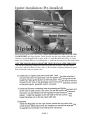
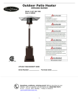
The Cape Fear Series
By
Wilmington Grill Company
Cape Fear Deluxe
Cape Fear Classic
OPERATOR MANUAL
8/01/06
THE ALL-STAINLESS STEEL GAS GRILL FOR
THE ULTIMATE GRILLING EXPERIENCE!
MADE FROM 304 GRADE STAINLESS
STEEL WHICH IS ONE OF THE HIGHEST RUST
RESISTANT MATERIALS AVAILABLE!
UL “Listed”
Retain these instructions for future reference!
INSTALLER:
Provide these instructions to the consumer after
installation!
DANGER
If you smell gas:
1.
2.
3.
4.
Shut off gas to the appliance.
Extinguish any open flame.
Open the lid.
If the odor continues, keep away from the appliance
immediately call your gas supplier of your fire department.
1. Do not store or use gasoline or other flammable liquids or
vapors in the vicinity of this or any other appliance.
2. An LP cylinder not connected for use shall not be stored in
the vicinity of this or any other appliance.
Warnings and Safety
PAGE 1
PAGE 2
This symbol identifies the most important safety messages in this manual. When you see this
symbol, be alert to the possibility of serious bodily injury if the instructions are not followed. Be
sure to read and carefully follow the messages
that follow. When a warning symbol precedes a
section title, the warning applies to all instructions in that section.
This symbol identifies hazards which could
result in minor or moderate personal injury or
property damage if the instructions are not followed. Be sure to read and carefully follow the
messages that follow. When a caution symbol
precedes a section title, the caution applies to all
instructions in that section.
LIMITED WARRANTY
Wilmington Grill Company, warrants all components of the Cape Fear Grill to be free from defects in
materials and workmanship. Within this period Wilmington Grill Company, shall correct any defect by
repairing or replacing defective parts of the equipment or making available the parts thereof. To obtain
warranty service the purchaser must deliver the grill or the defective part to the manufacturer. Shipping
expenses are the purchaser’s responsibility. Any service calls by our service technician are not covered under warranty.
Wilmington Grill Company, shall not be obligated to repair or replace equipment which has been
repaired by others, abused, altered, or misused. We further state that we will not be held liable for any
losses due to neglectful operation on the part of the purchaser. Upon the expiration of such warranty,
all such liability shall terminate. No other warranties are expressed or implied. This warranty is not
transferable. Warranty card must be returned within 60 days after purchase.
Store and city where purchased:______________________________________________________
Date:____________ Model:_______________________ Serial no:__________________________
WARRANTY
Cast Stainless Steel Burner
5-Year Limited
Cabinet Housing
Regulator
Control Knobs
10” rubber wheels
Steamer
Grate
Valves
5 years
1 year
1 year
1 year
PAGE 3
1 year
1 year
1 year
Do not use this appliance under overhead unprotected combustible surfaces.
This grill shall be used outdoors only, and shall not be used inside a building, garage
or any other enclosed area, on 2nd floor or upper level of any structure or residence.
The LP cylinder must be disconnected from the grill when not in use.
Only use 20-pound LP cylinders with a collar to protect the cylinder valve.
A shutoff valve terminating an LP cylinder valve outlet QCV-Type as
specified in the American National Standards for compressed gas
cylinder valve outlet and inlet connections, ANSI Z21.1.58b.
The safety relief valve to have direct communication with the vapor space of
the cylinder.
An arrangement for vapor withdrawal.
A bottom rim with holes for securing tank support assembly.
Figure 7 Applicable only to Propane models.
“Place dust cap on cylinder valve outlet whenever the cylinder is
not in use. Only install the type of dust cap on the cylinder valve
outlet that is provided with the cylinder valve. Other types of caps
or plugs may result in leakage of propane”.
Turn off LP-gas supply at cylinder when appliance is not in use.
Figure 7
Never light the grill when the lid is closed. Build up of gases is very
dangerous and could cause and explosion and injury or death.
Do not install or grill within 36” inches (10 ft. recommended) of combustible materials from the back and sides of grill.
PAGE 4
The grill is UL “Listed” per ANSI Z21.1.58b 2005
and CAN /CGA 1.66-MO2
20 & 21
PAGE 5
1,3,4
5
7,8,9,10
11,12,13,14
20,21
17,18
3
State and local ordinance requirements
Installation must conform with local codes or, in the absence of local codes, with either the National Fuel
Gas Code, ANSI Z223.1/NFPA54, National Gas and Propane Installation Code, CSA B149.1, or
Propane Storage and Handling Code, B149.2, or the standard for Recreation Vehicles, ANSI A
119.2/NFPA 1192, and CSA Z240 RV Series, Recreational Vehicle Code, as applicable.
PAGE 6
(REFER TO FIGURE ON PAGE 21):
This Cape Fear Model Gas Grill comes with the complete gas two burner
system, gas regulator, push button piezo spark igniters with
manual igniter tubes installed.
Orient item # 5 (Gas bottle tray) so the turned edge is down. Attach each leg
(items #2 and #3) to Gas bottle Tray edge downward on (Item #5) using two (1/4”
X 1/2”) bolts and nuts for each leg. Attach one short leg to the left end of the bottle tray attach second short leg directly across same end. Attach Item # 3 (long
legs) to item #5 (Gas bottle Tray) using two (1/4” X 1/2”) bolts and nuts for each
leg on right end of gas bottle tray. Attach second item #3 directly across same
right end using two (1/4” X 1/2”) bolts and nuts. Just slightly tighten all bolts at
this time. Attach Item #28 (short Leg cross brace) to each item #2 (short legs) One
bolt and nut per leg in holes provided in each leg located approximately 11 5/16
inches above the axle. Retighten all bolts and nuts after the grill is assembled.
PAGE 7
•
After you have completely assembled your new gas grill perform a
gas leak procedure .
•
Do a gas leak test on all connection using the procedure below.
1. Test for gas leaks, prior to beginning lighting procedure and whenever a new cylinder
is connected.
2. Follow these steps:
a. Make a soap solution by mixing one part liquid detergent and one part water.
b. Turn off all burner valves.
c. Turn Open LP Gas cylinder valve, turn counter clockwise to it completely stops.
d. Apply the soap solution to all gas connections.
e. Bubbles will appear in the soap solution If connection are not properly sealed.
f. Tighten or repair as necessary.
3. If you have a gas leak that you cannot repair, turn off the gas at the source.
4. Disconnect fuel line from grill and immediately call your grill dealer and/or gas supplier
for professional assistance.
5. Always do the pre-operation checks before lighting your gas grill. (See page 11)
PAGE 8
Igniter Installation (Pre-Installed)
Place manual igniter tube over Venturi (LONG SMALL ROUND SECTION OF THE
GAS BURNER) and align with the 1"hole located over the large oblong hole that the
Venturi is located through. Bolt in place with a 1/4 inch Hex head bolt using 1/4 nut on
under side. Push the Electro wire through the 1/4 inch hole located next to the burner bolts,
(NOT THE LARGE OBLONG HOLE THE VENTURI IS LOCATED THROUGH)
and slip the connecting terminal end over the generators terminal. The push button
generator is (Black or Red in Color) and is to be installed on lighting Instruction panel
item 16. Beside each gas control valve.
PAGE 9
PAGE 10
PRE-OPERATION INSTRUCTION
Check the cylinder to ensure that it is equipped with an OPD (overfill protection device)\
Have your new cylinder purged of air by your local gas dealer.
•
Check the cylinder to see that it is not empty.
•
Inspect the Valve connections, port and regulator assembly prior to each use. Look for
any damage or debris. Remove any debris if it is evident there is excessive abrasion
or wear, or the hose is cut, it must be replaced prior to the grill being placed into
operation. The replacement hose assembly shall be of that specified by this manual
and ordered from the manufacturer.
•
Check the air shutters at the burner valve interface to ensure they are properly located.
LIQUID PROPANE CONNECTION
Remove protective plastic cap from cylinder valve.
Align the Type1-LP Tank connector with the valve threads.
Turn the fitting clock-wise until snug.
Do not use a wrench to tighten.
Use of wrench may damage quick closing coupling nut and result in a
hazardous condition.
See figure below
If hazardous conditions occurs, move grill to open area make sure tank valve is in full off
position.
(Turn clock-wise to stop)
Make sure all burner valves are in their off position.
PAGE 11
•
Check for gas leaks. Prior to beginning lighting procedure and whenever a new
cylinder is connected. Follow these steps:
1. Make a soap solution by mixing one part liquid detergent and one part water.
2. Turn off burner valves. Open cylinder valve completely turn counter
clockwise to stop.
3. Apply the soap solution to all gas connections: bubbles will appear in the soap
solution if connections are not properly sealed. Tighten or repair as necessary.
4. If you have a gas leak that you cannot repair, TURN OFF THE GAS at the
source, disconnect fuel line from grill and immediately call your grill dealer and
gas supplier for professional assistance.
5. Check the air shutters at the burner and valve interface to ensure they are
properly located. See figure 12.
Figure 12
6. Inspect for loose screws or fittings. Tighten, repair, or replace parts as
necessary. Use only genuine replacement parts as recommended by this manual.
7. Set burner valves to off and LP gas cylinder valve to off.
8. Clean flame inhibitor tray if not cleaned previously. Use warm soapy water.
9. CAUTION: Keep flame inhibitor tray and drain free of grease build up to
prevent fire. Clean after each use.
PAGE 12
open Lid before lighting.
occur in 5 seconds,
The igniter button is located beside the
corresponding burner control knob. Press the igniter button that corresponds to the opened burner valve.
If ignition does not occur in 5 seconds, turn the burner
valve handles to off, wait 5 minutes, and repeat the lighting procedure.
If ignition does not occur in 5 seconds,
turn the burner valve handles to off, wait 5 minutes, and repeat the
lighting procedure.
PAGE 13
No.
12.
CAUTION! If the burners go out, turn off all gas valves. Open lid and wait
five minutes before attempting a re-light.
If fire occurs turn off all gas valves. Close lid and wait until fire goes out.
Never pour water on a grease fire.
.
PAGE 14
CAUTION! WARNING!
FOR YOUR SAFETY
• This model gas grill should be placed where the wind is not blowing greater than ten
miles per hour.
• NEVER place this grill where strong windy gusts occur, doing this will cause one or
both burners to be blown out.
• Don’t open the hood until you are 100% sure there is no gas build up or fire inside
the grill body.
• NEVER look inside the grill body through any type viewing holes to see if the burners
are burning.
• NEVER press the BLACK or RED piezo igniter button (located on the right and left
side of the lighting instruction panel) while the grill hood is in the closed position or
while looking through any type viewing holes.
WHAT TO DO IF THE WIND BLOWS OUT THE GRILL WHILE GRILLING OR
IF YOUR GRILLING TEMPERATURE HAS DROPPED OR YOU SMELL GAS.
1.
Immediately shut off all gas supply controls.
2.
Never open the hood or look through any viewing holes to check
and see if the grill is still lit.
3.
Turn the burner control valves to their OFF position.
4.
Wait five minutes for the gas to dissipate.
5.
Move the grill to a less windy area.
6.
Relight using the lighting instructions.
PAGE 15
When connecting the regulator assembly to the LP gas valve, check the
cylinder to see that it is not empty.
Check tank valve features to ensure it is equipped with a OPD
(overfill protection device). Use only tanks with valves marked: Type 1
device
Use only the the hose and gas pressure regulator supplied with this appliance or
a Wilmington Grill Company approved replacement.
PAGE 16
Fixed Fuel Line System Natural or LP Gas
Self contained LP-Gas Supply Systems
1. Have your local gas company to make the changes for you.
2. The outdoor cooking gas appliance and its individual shutoff valve must be disconnected from the
gas supply piping system during any pressure testing of that system at test pressures in excess of
0.5 PSI (3.5kPa).
3. The outdoor gas cooking appliance must be isolated from the gas supply piping system by closing
its individual manual shutoff valve during any pressure testing of the gas supply piping system at
test pressures equal to or less than 1/2” PSI (3.5kPa).
4. Gas valves use only Grand Mate type GM 701 with orifice – Brass, no.48 drill size (Natural Gas
Models use only).
5. Gas Valves use only Grand Mate type GM 701 with orifice – Brass, no.55 drill size (Liquid
propane Models use only).
6. Natural Gas-Hose Assembly, Part No.14TC120FS6FS6, 10’ foot hose mfg by Fairview Fittings.
Issue (CSA157808) No.1944.
7. Propane Gas Hose Assembly, Part No.14TC120FS6FS6, 10’ foot hose mfg by Fairview Fittings.
No, 14TC120FS6FS6 (UL Listed, MH-15646B).
8. Manifold Gas Flex Hose Assembly, Part No.14TC12.25FS6FS6 mfg by Fairview Fittings. (UL
Listed 7P52) Natural Gas or Liquid Propane.
PAGE 17
PAGE 18
Directions for Converting and Installation
of Natural Gas Self Contained Systems
1. Have your local gas company to make the changes for you.
2. On outdoor cooking gas appliances for connection to a self-contained gas supply, provision shall be
made between the supply cylinder regulator outlet and the main gas burner valve, by means of
either a flexible connection or a tubing loop, for expansion, contraction, jarring and vibration.
Aluminum tubing shall not be used for this purpose.
3.
Liquid Propane
Have your local gas company service person check for the proper
LP Gas Inlet pressure, set at 11 inches water column.
(Not above 2.74 kPa)
Natural Gas
Have your local gas company service person check for the proper
Natural Gas inlet pressure, set at 7.0 inches water column. (Not above 2.74 kPa) with a manifold
pressure not to exceed 4in WC,
4. Use a flexible hose connector complying with the current American National Standard for Gas
hose connectors for portable outdoor gas –fired appliances
ANSI Z21.54 be a minimum of 10 ft. and a maximum of 15 ft.
5. Shut off gas supply at the liquid propane cylinder, and remove from area.
6. Remove the Liquid propane regulator.
7. Connect the opposite end of the hose to the gas supply shut off valve
8. Located at the new gas source.
9. Gas supply piping and tubing shall be adequately supported and shall be removable.
10.You must have a gas shut off valve located on the Supply line at least 5 ft from the grill.
Natural Gas Conversion Kit Contains
1. Two (2) Grand Mate Type GM 701 Brass Valves with screw in orifice.
Drill Size # 48.
2. One (1) 10’ Flex Natural Gas Hose. Part #14TC120FSFS
3. One manifold connection hose. Part # 14TC12.5FS6FS6
4. One Natural Gas UL Label to be affixed to bottom shelf where it can
be easily read.
5. Instructions and diagram for installation.
PAGE 19
Item
1
2
3
4
5
Parts List
(Pre- assembled)
6
7
8
9
10
11
12
13
14
15
16
17
18
19
20
21
22
23
24
25
26
27
28
29
30
30
31
32
33
34
35
36
(Pre- assembled)
(Pre- assembled)
(Pre- assembled)
(Pre- assembled)
(Pre- assembled)
Manifold assembly
Liquid Propane Models.
(Pre- assembled)
Manifold assembly
Natural Gas Models
(Pre- assembled)
(Pre- assembled)
Not pictured
Not pictured
(Pre- assembled)
(Pre- assembled)
Hood and base sub-assembly with two hinges
Left leg (shortest leg)
Right leg (longest leg)
2
10” x 2” x 5/8” Rubber Wheels with bearing
Bottom shelf with tank hole for holding LP gas bottle.
Bottom shelf no hole for natural gas grills.
SS side shelf for right and left side of grill
Side shelf bracket for item 6
8
Cooking grate
Steamer pan (Purchase optional)
Support brackets for item 9 (Purchase optional)
Flame inhibitor tray with _” x 12” aluminum tube.
_”-20 UNC carriage screws, _” Long
_”-20 UNC nuts
Front panel with WG logo on deluxe models only.
or (purchase optional)
Axle 5/8” x 26 ?”
Lighting instruction panel and gas burner temperature control center
_”20 x3/4” UNC Hex bolts to fasten burner in place.
_” Brass ball or gate valve
1
Hood support bracket
Peephole covers with Teflon knob.
Front shelf (Deluxe model only or purchase optional)
Front shelf support bracket, for item 21
Side shelf handle
Piezo igniter assembly
Cotter pin, 1.75” Long
5/8” Washer one for each side of wheel hub.
Hood handle
Leg cross brace, Connects item 2 short leg too second item 2 short leg.
Prevents 2nd gas bottle from being stored under grilling unit.
Cast burners & air adjustment shutter with insect screen.
Qty
1
2
2
1
2
1
1
1
1
56
67
1
1
1
8
1
2
1
2
1
2
2
4
1
1
2
Contains two brass valves with propane orifices, one cross over hose
& one regulator with hose.
1
Contains two brass valves with natural gas orifices, one cross over hose
& one 10 ft flex hose for natural gas.
Hood damper
Teflon knobs for viewing hole covers or damper for item 20 or item 31
Temperature gauge
Bun warming half rack (purchase optional)
Manifold connecting hose
1
Grand Mate Valve Part # GM 701 natural gas #48 Drill
Grand Mate Valve Part # GM 701 propane #55 Drill
PAGE 20
1
3
2
PAGE 21
PAGE 22
COOKING TIPS:
1. The High setting is used for lighting and preheating of the grill only.
2. Open all vents in the hood while cooking, close vents only when you are
finished cooking and the grill has cooled.
This will help in keeping rain water out of your grill.
4. Searing your steaks and hamburgers.
5. Preheat the grill to 500˚F. Place your meats (steaks or burgers) on
the grilling grate close the grill hood and let cook while in the high position
for 5 minutes never leave your grill while cooking in the HI position with
greasy foods (sausage or hamburger patties or extra fatty steaks) you can
have a grease fire. Always reduce the control setting to low and wait for the
temperature to reduce before opening the grill hood especially before
turning greasy type meats. If a fire should occur close hood and close
hood vent, turn off main gas supply. This will cause the fire to extinguish.
Afterwards relight and cook at a lower setting.
Settings:
Lowest temperature for slow cooking is approximately 350˚F with
one burner
Lowest temperature range is approximately 375-400˚F with two burners
High setting is approximately 500-600˚F with two burners
CAUTION! Best cooking results are at 325-400˚F. Cooking at greater
than 500˚F may result in flare ups due to grease flash point.
TROUBLE SHOOTING:
Problem: Grill will not reach desired cooking temperature.
Solution 1: Turn burner valves to “OFF” position and open hood. Open the
LP gas cylinder valve and wait 10 seconds. Light according to lighting
instructions. This procedure readjusts the regulator safety check valve.
Solution 2: Follow pre-lighting instructions on page 10 and check for loose fittings, leaks and cuts in the regulator hose.
PAGE 23
PAGE 24
Thermometer Maintenance
Your thermometer can be reset when the temperature setting is incorrect.
To Reset:
Remove your thermometer from your grill.
The adjustment screw is located on the reverse side.
Use a flat screw driver to turn the screw.
Turning the screw moves the needle to your new setting.
!!WARNING!!
Never spray the thermometer with a water hose or pressure washer.
This will damage the seal and void the warranty.
If moisture collects in the thermometer remove it at once.
Replace with a new one.
The thermometer glass may break or crack or explode after water or moisture
collects inside.
Manufacturer warranties this thermometer for one full year.
(Send in warranty registration with the serial number to activate the warranty).
Thermometer returned under warranty must be shipped postage prepaid to:
Wilmington Grill Co.
3314 Enterprise Dr.
Wilmington, NC 28405
PAGE 25