1
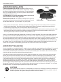
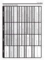
Owner’s Manual For all systems with 1/3hp (0.25kW) or 1/2HP (0.37kW) Compressor(s) Aeration Systems For Improving Lake, Pond & Marina Water Quality 2 Aeration Goals 7 Installation Steps 2 Warranty 8 System Start-up 2 Product Damaged in Delivery 8 Maintenance 3 System Materials List 9 Winter Operations 4 Safety 10 Compressor Diagram 5 Cabinet & Compressor 11 Troubleshooting Guide 6 AirStation TM Installation 12 Maintenance Log 6 AirStation TM Balancing 12 Parts List Vertex Water Features CONGRATULATIONS! You have purchased the most efficient and cost-effective aeration system available on the market today. Since 1992 the professionals at Vertex Water Features, as a division of Aquatic Systems, Inc., have been developing total lake management techniques. Your Vertex system will provide you with the highest quality lake aeration equipment in the industry. AERATION GOALS A Vertex aeration system will supply many important benefits to the overall health of a waterway: s Increased and constant oxygen levels throughout the entire water column. s Breakup of thermal stratification of the water column. s Elimination of oxygen-related fish-kill. s Reduction of nutrient levels and associated algae growth. s Allow for an increase in beneficial bacteria which are needed to break down organics. s Reduction of bottom muck and its accompanying foul odors. s Improved sport fisheries by expanding oxygenated habitat. s An overall healthier waterway ecosystem ... naturally! PRODUCT WARRANTY Vertex Water Features will repair or replace any defective part within the compressor cabinet for a period of two years from date of receipt. The AirStation™ diffuser assembly will be warranted for a period of five years and BottomLine™ tubing will be warranted for a period of 15 years. Air filters and compressor maintenance kits are wearable parts and not covered under this warranty. Customer is responsible for return shipping of any goods for warranty inspection by Vertex Water Features. After inspection, if product shows manufacturing defect, Vertex will replace or repair it at no cost to customer. Should inspection indicate non-warranty failure (incorrect voltage, faulty installation procedures, vandalism, customer negligence, etc.) warranty will be void. Painting the cabinet will cause the internal components to overheat and void the warranty. The warranty period for all warranty work is equal to the remaining time period of the original new equipment warranty. Warranty claims are based on the date you notify your dealer or Vertex Water Features at 800-432-4302. All claims must be made to Vertex Water Features or an Authorized Dealer. NOTE: Vertex reserves the right to change this information without notice, and makes no warranty, express or implied, with respect to this information. Vertex shall not be liable for any loss or damage, including consequential or special damages, resulting from the use of this information, even if loss or damage is caused by Vertex negligence or other fault. 2 Warning: Installing this aeration system in any of the following ways will void your two year compressor system warranty. Call your dealer or Vertex Water Features for help resolving installation problems. Installing the cabinet inside a box, shed or other enclosure traps the cabinet exhaust heat and rapidly overheats the compressor and motor. Providing undersized electrical supply wires that can’t maintain required voltage when compressor is running under load causes high electrical resistance, severe compressor vibration and premature motor failure and compressor head damage. Painting the cabinet exterior elevates interior cabinet temperatures and damages the motor and compressor. Installing a cabinet in too low an elevation allowing it to flood. Water entering the cabinet will destroy the motor, compressor, cabinet fan(s) and GFCI receptacle. Installing the cabinet is an unusually dirty environment. Excessive airborne dirt, sand or grit entering the cabinet will damage the motor and compressor. Owners Manual CHECK MATERIALS UPON DELIVERY FOR PRODUCT DAMAGED IN DELIVERY The aeration system was properly packed and accepted by the freight carrier for shipment. It is therefore their responsibility to deliver the system in perfect condition. APPARENT DAMAGE OR LOSS If upon delivery the equipment or containers indicate DAMAGE IN TRANSIT, such goods should be refused or not accepted until the transportation company’s agent has noted such on the freight bill. A copy of such bill will be given to you, noting the nature and extent of the damage. If any part of shipment is LOST IN TRANSIT, have shortage noted on freight bill by agent. CONCEALED DAMAGE If damage is discovered, that was not apparent upon delivery, notify the transportation company immediately to inspect damaged equipment. The inspector will be required to provide a “CONCEALED BAD ORDER” report. Inspections must be requested within 15 days of delivery. Do not move damaged goods from original point of delivery. Retain all original packing and containers for inspection. File a “FULL VALUE REPLACEMENT” claim against the transportation company. Hours of Operation: M – F, 8am – 5pm EST Phone: (800) 432-4302 Fax: (954) 977-7877 Web: www.vertexwaterfeatures.com Email: [email protected] © 2010 Vertex Water Features SYSTEM MATERIALS LIST Verify that you received the following: QuietAir™ Compressor Cabinet with Piston Compressor: The cabinet is constructed of aluminum and electrostatically powder-coated to provide a lifetime protection from rust. The cabinet houses the compressor(s), inlet filter/muffler assembly, air outlet hose, and ventilation fan. NOTE: Your cabinet model may be different from the example photo. Check to make sure you have the correct type and quantity of CoActive™ Flexible Membrane AirStations™ based upon your order. Please refer to your invoice or packing slip for reference. XL2 Diffuser XL2SW AirStations™: Designed specifically for shallow water applications from 4'- 8' (2.5m - 3.0m) deep, this unit utilizes two 9" (23 cm) diameter flexible membrane diffuser disks of EPDM construction incorporated into a single vacuum formed hollow base unit per AirStation™. XL2 AirStations™: Designed for 10'-16' (3.0m - 5.0m) applications, XL2SW Diffuser this unit has two 9" (23 cm) diameter flexible membrane diffuser disks of EPDM construction incorporated into a single vacuum formed hollow base unit per AirStation™. XL4™ AirStations™: Designed for 14'-30'+ (4.3m - 9.2m+) applications, this unit has four 9" (23 cm) diameter flexible membrane diffuser disks of EPDM construction incorporated into a single vacuum formed hollow base unit per AirStation™. XL5™ AirStations™: Designed for 8' and deeper (2.5m+) applications, this unit has five 9" (23 cm) diameter flexible membrane diffuser disks of EPDM construction incorporated into a single vacuum formed hollow base unit per AirStation™. XL4 Diffuser XL5 Diffuser Poly Plastic Mounting Pad Installation Manual Compressor with Valve Manifold and Muffler Assembly 3 Vertex Water Features SAFETY NOTES Please read the following instructions carefully before installing and operating your aeration system. Failure to follow the recommendations in this section may result in personal injury or rescinding of the machine warranty agreement. WARNING Risk of electric shock - this pump is supplied with a grounding conductor and grounding-type attachment plug. To reduce risk of electric shock, be certain that it is connected only to a properly grounded, grounding-type receptacle An improper connection to the aerator grounding conductor can result in electrical shock. DROWNING DANGER DANGER THIN ICE Operating in freezing conditions on an ice-covered lake will cause large open water areas to remain at the boil sites. The ice thickness around these open areas will be much thinner than the ice over the rest of the lake. Injury or fatality may result from falling through the ice. Vertex strongly recommends that this danger of thin ice around the boil area be clearly posted at frequent intervals. Owner assumes all responsibility for operating Vertex aeration systems during winter months. s Always connect the cabinet to a properly grounded outlet. If in doubt, have the outlet checked by a qualified electrician. Open water and thin ice caused by aeration s Never use an extension cord between the cabinet power cord and an electrical outlet. s Do not allow anything to rest on the power cord. s Do not place the cabinet where people may step or trip on the power cord. s Follow all warnings and instructions that are marked on or supplied with the aeration system. s Never override or “cheat” electrical or mechanical interlock devices. s Always locate the cabinet on a solid support with adequate strength for the weight of the unit. s Install the cabinet at a distance and location safe from standing water or flooding per National Electric Code 682 and all local codes. s Locate the cabinet away from irrigation sprinklers. s Never push objects of any kind into the slots in the covers, as they may touch dangerous voltage points or short out parts that could result in a risk of fire or electrical shock. s Never attempt any maintenance function that is not specified in the user manual. s Never remove any covers or guards that require a tool for removal, unless you are instructed to do so. Ensure that you read all Warnings and Cautions, and follow each step in the instructions exactly as they are written. s Never attempt any activity that is not specified in the user manual, or that is not specifically directed by an authorized Vertex representative. s Never operate the system if unusual noises or odors are detected. Disconnect the power cord from the outlet and call Vertex to correct any problems. s Before performing any maintenance and troubleshooting, disconnect the electricity by turning off all circuit breakers and unplugging cabinet. s When in or around water wear a Coast Guard approved life jacket and follow all water safety guidelines. s Refer to these instructions as needed in order to ensure the safe operation of the aerator. 4 Owners Manual CABINET INSTALLATION GUIDELINES Your cabinet was shipped with a plastic mounting pad attached. You may use this pad for the final installation or a cement pad may be needed in areas where vandalism is a potential problem. To use the plastic pad simply clear the ground of any rocks, sticks and debris that will prevent the pad from sitting flat. You may need to use a shovel to level the ground to achieve this. Check the final placement with a level. To minimize compressor noise, place cabinet directly on the ground, surrounded by landscaping. Note: Place the pad so that the air lines leaving the cabinet face the lake. Using this method, the cabinet installation is now complete. WARNING Painting the cabinet will cause the internal components to overheat and void the warranty. IF A CEMENT PAD IS REQUIRED A wooden form must be built to pour a pad. Place the cabinet and plastic pad on the ground in the location that you want it. Dig out around the pad using the pad as an outline, Dig the hole 3" (8cm) deep. Insert your form into the hole leaving at least 1" (2.5cm) of wood form above the ground level when complete. Mix the concrete and pour it up to the top of the form. Using a trowel, skim the top for a nice finish. The concrete should set within 48 hours, colder climates may take longer. Wood form Once the concrete has cured, simply take the cabinet and plastic mounting pad and place them on top of the cement pad. Drill four holes, one in each corner of the plastic pad using a masonry drill bit. Insert a wedge anchor through the plastic pad and into the cement. Using the nut and washer supplied with the anchor kit, fasten the plastic pad to the cement pad you made. Installation of the cabinet is now complete. 1" (2.5cm) 3" (8cm) 5 Vertex Water Features AIRSTATION INSTALLATION Diffuser Disk Correct placement is critical: the ability of the system to affect your waterway depends on the position of the diffuser. It should be placed in the deepest areas of the water body. To make installation easier you should know where you intend to place the diffuser before starting the installation process. CAUTION: When in or around water always wear an approved life jacket and follow all water safety guidelines. Materials FOR set up: The AirStation, Waterproof PVC glue or a screw driver and hose clamp, a utility knife, and enough rope to reach the lake bottom and back: 10' (3.0m) depth = 20' (6.1m) rope). Plug AirStation Base Airline Connector Once you have returned to shore, attach the open end of the supply tubing to the hose coming out of the compressor cabinet via the barbed fitting. Secure and tighten stainless steel clamps to both supply tubing and compressor hose. Trench and bury supply tubing runs from compressor cabinet to water’s edge. Contract a licensed electrical contractor to bring 115 or 230 volt (depending on which aeration model is purchased), single phase electrical supply to the cabinet and install a weatherproof receptacle. (QA4 cabinet available in 230v only. All 230 volt systems require customer to provide a GFCI protected circuit) Vertex 115 volt aeration systems are equipped with a Class A GFCI outlet receptacle. This outlet is specifically installed for personal protection and should NEVER be replaced by a non-GFCI outlet without first consulting Vertex Water Features. Due to the fact that aerators often experience damp or wet environments, any faults in non-GFCI equipment or circuits could have fatal consequences. Since Vertex 115 volt aeration systems have a GFCI outlet, plugging them into another GFCI outlet can cause “nuisance tripping” resulting in persistent system shut down. It is recommended that only one GFCI outlet be used per circuit. For more information on the GFCI and operations testing see the GFCI Guidelines on page 10 of this manual. 230 volt systems are available by special order but do not have a Class A GFCI receptacle. AIRSTATION™ BALANCING Once the installation of a multiple AirStation™ system has been completed, proper balancing of the AirStations™ is required to ensure that they all get an equal amount of air. The control valves for each AirStation™ are located inside the cabinet, unless a VBS (Valve Box System) was installed. In the instance that a VBS system was installed, the control valves will be inside the valve box, buried to ground level, down by the shoreline. Close all blue AirStation valves except the one with the longest (or deepest) run of tubing. With this one valve wide open, partially open the valve that controls the air flow to the AirStation™ with the second longest (or second deepest) run of tubing. Continue this process of adjusting the second valve until a boil is noticed above this AirStation™. Leave the valve in this position and move on to the next valve and repeat the process. Continue working your way from the longest (or deepest) to the shortest (or most shallow) run of tubing. Once there is air to all of the AirStations™, check to be sure all boils are approximately the same size. If they are not, make small adjustments as necessary to even them out. At this point we suggest making indicator marks with a permanent marker from the valve handle to the valve body to assist you in rebalancing the system in the future. The overall goal when adjusting the valves is to balance the AirStation™ at the lowest possible pressure. The lower the system pressure the higher the total air flow. 6 CAUTION If the system has been installed in an established pond, and you are attempting to balance the AirStations™ during the first day of operation, make certain that this procedure takes as little time as possible. Under 30 minutes is preferred. See “System Start-up Procedures” section for details. Owners Manual INSTALLATION - Following these steps will prevent the AirStation™ from inverting. 1 2 Fill the base up with river rock or gravel. Do not use sand. After filling, pick up at base only. 4 3 Insert the plug and the airline hose adapter Screw diffuser discs onto riser pipes, do not cross thread. Pick up assembled airstation by black base only. 5 6 Assemble all the materials you will need on Uncoil the air supply tubing along the shore Leave 4' (1.22m) extra tubing on shore the boat - see list on page 1. making sure the tubing is not and secure one end of the tubing so twisted or tangled. that it doesn't follow you into the water. 7 8a 8b OR Head out with the other end of the tubing. Make sure the propeller and tubing do not get tangled up. 9 At the drop site, connect the tubing to the barbed fitting. Use PVC cement and let dry (recommended method), or... 10 Thread rope through the two holes on the base until the rope is evenly distributed.* Holding both ends of the rope in your hand,carefully lower the diffuser assembly into the water. Connect the tubing to the barbed fitting with a hose clamp. 11 Once unit is on lake bottom, release one end of the rope and pull rope into the boat. Follow the start-up procedures on page 8 *If future movement of the Airstation is anticipated, tie one end of rope to the unit and, after it settles on the bottom, tie the other end to a buoy or decoy on the surface of the water. 7 Vertex Water Features FIRST TIME AND SPRING START-UP PROCEDURE Aeration systems circulate the lake's entire water column. The aeration system will circulate deep, poor quality water that accumulates over time upward to the lake’s surface introducing harmful gasses into the previously healthy upper regions of the water column. This movement of water can temporarily affect aquatic life and could result in a fish kill. To prevent a fish kill, Vertex has established the following start-up procedures, this should take 7 days: Turn on system and operate for 30 minutes. Turn off system for remainder of the day. Restart the system the next day and operate for 60 minutes. Turn off system for the remainder of day. Each day double the operating time from the previous day until the system is running continuously. This should take 7 days NOTE: These start-up procedures are a general guideline. If you should have any questions and/or concerns, contact Vertex Water Features at 800-432-4302 for technical assistance. MAINTENANCE SAFETY Always use parts that are supplied or approved by Vertex. Use of other parts may result in poor performance and could create a hazardous situation and void the warranty. Do not use acid or corrosive cleaners. Follow instructions in manual for the appropriate cleaning methods. Refer servicing to a qualified electrician under the following conditions: - When the power cord is damaged or frayed. - Compressor fan, outlet or other electrical components need service. - If the cabinet is producing unusual noises or odors. Vertex aeration systems are designed for low-maintenance and typically only require minimal scheduled maintenance. Periodic cleaning and/or replacement of the compressor air filter, piston cup, and “Flexing” of the AirStation™ is required. Remember to keep cabinet air inlets and outlets free of debris and weed growth to allow normal ventilation. If size and appearance of any surface boil has decreased from initial installation, perform one or both of the following: AIR FILTER CLEANING/REPLACEMENT** Air filter cleaning or replacement: Remove compressor air intake filter and wash with soap and water or replace. This should be done 2-4 times per year. Never re-install a wet or damp filter. Twist to unlock Remove old air filter Insert new air filter Line up the notch on top With the notch on the bottom Twist to lock **On the inside of the cabinet lid or the outside back cover of this Owner’s Manual you will find a Vertex parts list that provides you the necessary parts information for ordering replacement parts. Call Vertex at 800-432-4302 with your 4 digit system warranty number or serial number off of the silver ETL sticker, found inside the cabinet. Vertex can also supply you with the necessary replacement parts information. PISTON CUP REPLACEMENT Under normal year-round, continuous use, the compressor piston cups typically last 24-36 months. As the piston cups wear out you’ll notice a drop in air flow (despite air filter replacement) resulting in smaller surface boils. 8 Owners Manual CABINET COOLING FAN REPLACEMENT Cooling fans provide critical cooling for the cabinet components. If the cooling fans fail, cabinet temperatures will drastically increase and damage the compressor system. For systems that run continuously, we recommend replacing the cooling fans every two or three years. A convenient time to replace the fans is during compressor maintenance. DISK FLEX-CLEANING PROCEDURES Routine maintenance of the AirStation™ disks is recommended once per year. This procedure is known as disk flexing. Over time organic matter and algae can settle on the AirStations™ and inhibit the release of micro-bubbles, in turn reducing the effectiveness of the AirStation™. Disk flexing helps unclog the pores in the membranes, reduces back pressure on the compressor(s), and restores the performance of the AirStation™. Disk flexing is very easy and is done from the cabinet or valve box location. The control valves for each AirStation™ are located inside the cabinet, unless a VBS (Valve Box System) was installed. In the instance that a VBS system was installed, the control valves will be inside the valve box, buried to ground level, down by the shoreline. Open the cabinet and make a line with a permanent marker on each valve body and handle that line up with each other in the valve’s present position. This will help re-balance the system once your finished flex cleaning the disks. Close half the valves. Close the lid and turn on the system for two minutes Turn off the power and unplug the cabinet and close the valves that were just flexed. Open the valves that were previously closed. Close the lid and turn on the system for two minutes Return all valves to their original, balanced positions by aligning the marks you made on the valve bodies before starting the procedure. If you have not yet balanced the AirStations™, or cannot read your indicator marks, see the “AirStation™ Balancing” section on page 6. The Disk Flex Cleaning procedure is now complete. OPERATING THE SYSTEM IN THE WINTER Vertex Aeration Systems are designed to operate year-round in cold climates with these important precautions. If you choose to run the aeration through the winter: Operating in freezing conditions on an ice-covered lake can cause large open water areas to remain at the boil sites. DANGER THIN ICE WARNING: ice thickness around these open areas is thinner than the ice over the remainder of the lake. Injury or fatality may result from people, snowmobiles, etc. falling through the ice. Vertex strongly recommends that this danger of thin ice around the boil area be clearly posted at frequent intervals. Owner assumes all responsibility for operating Vertex aeration systems during winter months. Open water and thin ice To prevent risk of freezing the entire water column, AirStations™ should be moved caused by aeration to a shallower portion of the waterway (typically one-half the depth of original placement) and operated there until warmer temperatures return, this will allow warmer water to remain in the lower regions of the waterway and prevent water column freezing. The airline tubing on shore and the compressor hose must be insulated between the cabinet and the ground. Also, the tubing must enter the water below the winter ice depth. If you choose to turn off the system for the winter: Just unplug the system; no other equipment preparation is required. In the spring, when the system is restarted, air lines may still contain ice inside the line. One cup of denatured alcohol added to each frozen line will melt the ice enough to allow the compressor to push air through the line until heat generated by the compressor melts the remaining ice. Follow the first time and spring start-up procedures described on page 6. 9 Vertex Water Features GFCI GUIDELINES A GFCI receptacle is different from conventional receptacles. In the event of a ground fault, a GFCI will trip and quickly stop the flow of electricity to prevent serious injury. THE GFCI’S FEATURES A GFCI receptacle only protects against ground faults, not circuit overloads, short circuits, or shocks. For example, you can still be shocked if you touch bare wires. TEST THE GFCI A B A RECEPTACLE B OUTLET C C TEST BUTTON D D RESET BUTTON E MOUNTING BRACKET If the GFCI is not operating correctly it may not prevent personal injury or death due to a ground fault. Press the TEST button in order to trip the device. This should stop the flow of electricity, making the fan/compressor shut OFF. If the power stays ON, contact Vertex. If the power goes OFF, the GFCI receptacle is working correctly. Perform GFCI testing monthly to assure proper operation. E If the GFCI does not reset or operate correctly, call a licensed electrician for repair or replacement. See page 8 for additional GFCI information. QA1 Cabinet A B C D E F G H I I F C E AIRSTATION VALVES CABINET FAN AND GUARD CAPACITOR CHECK VALVE COMPRESSOR FAN/GUARD INTAKE FILTER/MUFFLER PRESSURE RELEASE VALVE SOLENOID VALVE PRESSURE GAUGE QA3 Cabinet I A D H G B F G E QA2 Cabinet F C E G A 10 B I H D C B Compressor beginning to lose compression and needs piston rebuild kit. Valves in cabinet are properly "balanced" and no leaks are evident. Compressor shakes erratically and makes load noises. Compressor stops working for periods of time, then restarts. Air coming out of pressure relief valve Large rolling bubbles instead of fine bubbles at surface above one or more AirStations No bubbles at one or more, but not ALL AirStations. Compressor and cabinet fan are running. If gauge of circuit wiring is incorrect, have electrician replace. NEVER use extension cord to operate system as it will cause a voltage drop and damage the compressor. Gauge of supply wires to circuit possibly undersized, or cabinet is plugged into extension cord. Low voltage damages compressors and voids your warranty. Voltage must be checked while the compressor is running at pressure Muffler filter in need of replacement, or blockage of silencer tube in muffler cap. Check for low voltage while compressor is running under load. Check for clogged muffler or blocked silencer tube in muffler cap. Clean or replace filter. NEVER re-install a wet filter. Remove debris clogging silencer tube in muffler cap if blocked. Contact Vertex or local dealer for fan replacement. Leave top of cabinet open for cooling if possible, otherwise unplug system until fan is replaced. Contact Vertex or local dealer for repair/replacement. Compressor overheating due to bad fan. Bad pressure relief valve. Inspect fan for proper function. Low pressure reading on gauge. AirStations not clogged. High pressure reading on gauge. Inspect AirStations and tubing for clogging. Contact Vertex or local dealer with compressor specifications for rebuild kit. Keep muffler filter clean. Adjust valves on manifold in cabinet until all AirStations operate properly. See "AirStation Balancing" section for instructions. Regular disc flexing not performed. Flex discs 2 times per year to help avoid clogging Improper "balancing" of AirStations. Are all valves in cabinet wide open? Call Vertex or local dealer for repair/replacement. AirStations partially blocked up Solenoid valve bad. Obvious air leak from solenoid valve. No bubbles at one or more AirStations, most likely all. Compressor and cabinet fan are running Tighten loose connection or replace cracked fitting as necessary. Rebalance air flow to AirStations Vibration loosened connection, or cracked fitting. Check for leaks at all connections in line and in cabinet. If none are audible, carefully spray SMALL amount of soapy water onto connections and look for bubbles. No bubbles at one or more AirStations, possibly all. Compressor and cabinet fan are running Contact Vertex or local dealer with specifications for rebuild kit. Keep muffler filter clean. All valves closed too much Compressor needs piston rebuild kit and possibly new muffler filter. Compressor operating normally or making unusual noises. Exhibits reduced pressure/air flow. No bubbles at ANY AirStations. Compressor and cabinet fan both running. Clean or replace filter. NEVER re-install a wet filter. Remove debris clogging silencer tube in muffler cap if blocked. Call Vertex or local dealer for repair/replacement. Compressor muffler filter is dirty/clogged or silencer tube in muffler cap is blocked. No air leaks are audible in cabinet. Compressor running louder and possible excessive vibration. Contact Vertex or local dealer for repair/replacement. Contact Vertex or local dealer for repair/replacement. Contact Vertex or local dealer for instructions. CORRECTION Diffuser membrane damaged, or AirStation fitting broken. Compressor is bad. Capacitor has been replaced. Inspect each AirStation for malfunction. Bad capacitor. No bubbles at ANY AirStations. Compressor not running, but cabinet fan is. No capacitor wiring issues can be seen. LIKELY CAUSE Wiring loosened or was damaged during shipment or maintenance. CHECK Unplug system. Check compressor capacitor wiring for frays or poor connections. ISSUE Owners Manual TROUBLESHOOTING GUIDE MAINTENANCE SCHEDULE DANGER: To prevent severe shock or electrocution, always turn the power OFF at the service panel before working with electricity. Date: Maintenance Performed: Date: Maintenance Performed: Date: Maintenance Performed: Date: Maintenance Performed: Date: Maintenance Performed: Date: Maintenance Performed: Hours of Operation: M – F, 8am – 5pm EST Phone: (800) 432-4302 Fax: (954) 977-7877 Website: www.vertexwaterfeatures.com Email: [email protected] 0310/CAHF


![[54] W, rm-pg`vzvlsggéggllslswnolq MONITOR OTHER](http://vs1.manualzilla.com/store/data/005697201_1-5cf72edac23b396dc325f3c508f97781-150x150.png)