1
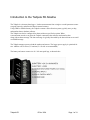
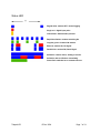
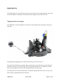
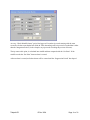
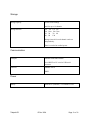
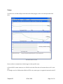
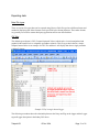
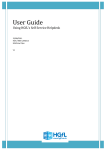
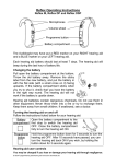
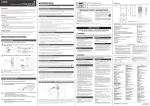
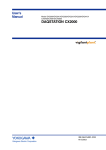
Isodaq Tadpole R2 Data Logger - Alkaline
Version
User Guide
Tadpole R2
12 Dec 2014
Page 1 of 38
Introduction to the Tadpole R2 Alkaline
The Tadpole is a telemetry data logger . It takes measurements from a single or a multi-parameter sensor
at regular intervals, and stores this data in internal memory.
Using GPRS or GSM telemetry, the Tadpole contacts a data collection system, typically once per day,
and transfers data to the data collector.
The Tadpole can also be configured for alarms with user-specified set points. When
a measurement exceeds a set point, the Tadpole contacts the data collector and transfers data
along with an alarm message. The alarm message is typically forwarded by the data collector as an email
or an SMS message.
The Tadpole manages power to both the modem and sensors. The logger power supply is optimized for
two Alkaline cells in series (3V nomimal, 2 x D cells are recommended)
The battery and sensor connect via 4.8 * 0.8 mm spade lugs, as shown below.
Tadpole R2
12 Dec 2014
Page 2 of 38
Contents
Introduction to the Tadpole
Contents
Telemetry setup
Access to Timeview
SIM requirements
SIM installation
Status LED
Telemetry introduction
Telemetry protocols
Receiving data via GPRS
Polling or check-in
Time switching
Check-in calls
Dial outs
Logger configuration for Timeview
Frequently asked questions
General
Telemetry
Batteries
Battery life
Applications
Tipping-bucket rain gauges
Rainfall intensity alarms
Specification
Sensor inputs
Sensor Power Supply
Storage
Communication
Power
Mechanical
Tadpole R2 Dimensions
Tadpole R2
12 Dec 2014
Page 3 of 38
Declaration of Conformity
Hardware & Accessories
Tadpole System components
Harvest software
Getting Harvest software
Installation
Usage
Local wired comms
Remote telemetry
Modems
Data retrieval: XDQ files
Reading the current configuration
Reading parameters only
Resetting after reading
Changing logger configuration
Group and tag specification
Changing sensor type
Sensor calibration
Dial outs
Exporting data
Data File types
CSV files
Reconfiguration
Sending Commands
Monitor Comms
Upgrade Logger Firmware
Tadpole R2
12 Dec 2014
Page 4 of 38
Telemetry setup
This section describes how to set up the logger for use with Timeview Telemetry, the web-based data
collection and alarm forwarding service operated by Isodaq Technology.
Note that if you have ordered your Tadpole with a Timeview Telemetry package, it will most likely be
already configured correctly and tested. However, it is strongly advised that the user still confirm that the
system is correctly configured and communicating properly before leaving to go site.
Access to Timeview
Before starting, an account on www.timeview2.net is required.
A logger profile is also needed on the account for every logger connected to Timeview.
Accounts and logger profiles are created by the Timeview administrators, once the service has been
ordered. The user will not be able to see data or receive alarms from a logger until these steps have been
completed. Once the user can log-in to Timeview and see the logger profile, they can configure the logger
to connect to it.
If Timeview Telemetry is being ordered for a logger you already have, please ensure that the following
information is specified with the order
1. Account name
2. Logger serial number
3. Group and Tag from logger configuration
If you are ordering a new logger for use with Timeview, you can omit the logger serial number from the
above list.
SIM requirements
Clients within the UK may arrange SIMs to be supplied with part of the Timeview package. This will
ensure they are correctly configured to access the data collection server.
If you are supplying your own SIM for an Tadpole, please ensure that the SIM meets these requirements:
The SIM must be:
● GPRS enabled, with internet connectivity. A monthly usage of 1MB is sufficient for most sites
with daily data check-in. Fixed-IP SIMs are generally not necessary.
● Data Enabled - it must support GSM CSD data. This is important even if the site to be used with
GPRS. Record both the voice and data numbers of the SIM – they are usually different.
● SMS enabled, especially for incoming messages. Outgoing message are sometimes useful but not
essential.
● Free from password protection . Test the SIM in a normal phone to ensure there is no password
request, and if necessary disable the password via the phone’s security settings.
Tadpole R2
12 Dec 2014
Page 5 of 38
SIM installation
Tadpole SIM fitting
1. Open the SIM cap by loosening the two screws.
2. Insert the SIM as oriented above. Push it into the slot and it should click and stay in place. To
remove it, push it again and it should click and pop out. This push-push behaviour only works if
the SIM is correctly oriented. To avoid telemetry issues, ensure that the SIM pushed in before
refitting the cap.
3. Replace the SIM cap oriented as shown above and tighten the two screws to seal the cap.
Note: It is essential that the SIM is correctly inserted into the slot before refitting the cap. Failure
to do so may result in poor or no telemetry connection.
Tadpole R2
12 Dec 2014
Page 6 of 38
Status LED
Regular blue: modem OFF, normal logging
Single red - digital input pulse
Yellow flash: dialout button pressed
Rapid blue flashes: modem switching On
Irregular green: Comms with modem
Blue/red: modem On, No Signal
Double blue: modem ON, Good Signal
Solid blue: comms active, waiting to receive
Solid blue with red flashes: transmitting
Green flash: switched on or comms time-out
Tadpole R2
12 Dec 2014
Page 7 of 38
Telemetry introduction
This section summarizes the telemetry methods used, and how telemetry is configured.
Telemetry protocols
The telemetry protocol specifies the exact message format used to transfer data from telemetry loggers.
It’s not sufficient to specify “GPRS”, since this does not state the message format.
Telemetry protocols require two-way communications, and are designed so that error-free data delivery is
guaranteed.
The Tadpole supports two telemetry protocols: A modbus ASCII scheme for transfer of alarms, time
series data and configuration, and DNP3, an industry-standard SCADA protocol. These protocols are used
to communicate with the following telemetry servers:
Telemetry server
Protocol
Isodaq Harvest
Modbus
Isodaq Timeview
Modbus
Isodaq Timeview Virtual Appliance (TVA) Modbus
Isodaq XDQ Server
Modbus
Serck SCX
DNP3
CSE Servelec Scope-X
DNP3
Kisters SODA
Modbus
Tadpole R2
12 Dec 2014
Notes
1
2
5
3, 4
3, 4
3
Page 8 of 38
Notes:
1. Suitable for manual dialling only. Necessary for logger configuration. Not suitable for receiving alarm
calls.
2. Web-based collection; no software needed for browsing data at the client.
3. Driver and version upgrades may be required from your SCADA supplier to enable DNP3 support.
4. The DNP3 Device Profile Document for the Tadpole is available from your Isodaq supplier.
A firmware upgrade may be required to support DNP3, but this can be installed remotely over GSM or
locally via Harvest without removing the logger from site. Please specify you require DNP3 when you
order your loggers by adding the -DNP3 option to the order code.
5. The Timeview Virtual Appliance (TVA) provides the functionality and exibility of Timeview, which is
the core of Isodaq alarm and data forwarding systems. TVA is only suitable for GPRS applications, since
there are no modems supplied with it. TVA runs under any MS or other operating system that supports
VMware Virtualization Products. TVA can also run under native VMware infrastructure products.
Receiving data via GPRS
GPRS data collection uses no modem at the receiving end. Data comes in directly over the internet - the
Tadpole “dials out” to a URL (a web address).
Setting up a web address to receive GPRS calls requires IT expertise, and depends on the network
configuration at the organization hosting the data collector.
Unless fixed IP SIMS are used, only check-in mode (logger originated calls – see below) is supported for
GPRS. Loggers can still be polled via Harvest and a modem if the CSD data number of the SIM is
known.
Polling or check-in
There are two methods of retrieving data from telemetry loggers:
• Polling, where the data collector originates calls to outstations
• Check-in, where the outstation originates calls to the data collector
Polling has advantages where the logger must be contacted by the data collector on demand.
Check-in has advantages of lower power consumption, and of daily test of potentially critical alarm calls.
Isodaq Telemetry Loggers support both methods, although check-in is generally preferred for reasons
outlined in the following sections.
Tadpole R2
12 Dec 2014
Page 9 of 38
Modem power management
GSM/GPRS modems use significant power when they are left switched on so the logger can receive calls.
Power is mainly consumed by the radio receiver, and is higher in weak signal areas.
For extended battery life, the modem should be switched off for most of the time. Time-switching is one
way of doing this, where the outstation can be contacted during several ‘windows’ of time where the
modem is powered. However, this still means that the modem can be on for hours each day, waiting for
calls.
It can be difficult to contact an entire network of outstations during the time-switch window, leading to a
complex system of different windows for different parts of the network.
For good battery life, we recommend the modem is left on for at most 15m per day.
If you leave the modem on for hours per day, you will have significantly reduced battery life.
Note that the Tadpole uses a GSM modem with a special low power mode which greatly extends the
battery life when the modem is on.
Time switching
Time switch times must be specified in the format HHMM (eg 2210 for 10:20 pm). Specify them in
normal time, not daylight saving time, so you may need to subtract an hour if you are configuring the
outstations in the summer. Notes on modem time switching:
• If the remote system loses power, the ON and OFF times will be incorrect and you will not know when
the remote modem is switched on. The error will not be the same as the duration of the power failure. It
can only be corrected by reconfiguring the time-switch settings, which may be difficult if the site is
remote and modem is off!
• The modem will switch on and remain on for 10 minutes after a Tadpole is powered up, after an alarm,
or after it is dialled for a (polled) data collection. You can force the modem to switch off after one of
these events with a ModemOff command from Harvest either locally or remotely.
Tadpole R2
12 Dec 2014
Page 10 of 38
Check-in calls
To avoid the problems with time-switched polling, the Tadpole can be programmed to ‘check-in’ every
day, automatically switching on the modem, dialling out, waiting for the call to be answered, then
powering down the modem.
This method allows the modem to be powered for the shortest possible time. The check-in call is virtually
identical to an alarm call, except that the message does not contain an alarm trigger. This is an important
feature for enhanced reliability - it is a daily self-test of behaviour that becomes critical in alarm
conditions.
You do not get this with systems that rely on polling for data collection. Outstations will attempt to
check-in at a random times between the two specified check-in times.
For a small network of outstations, the check-in times can be reasonably close together, say 30m apart.
Larger networks can allow all day to check-in, with times of 0030 to 2330 specified.
If either check-in time is set to 0000, the check-in feature will not operate.
Note times must be specified in normal time , not daylight saving time, so you may need to subtract an
hour if you are configuring them in the summer.
Daily check-in can be used along with time switching. A short time-switch period can be set after the
latest check-in time in case the outstation needs to be contacted for reconfiguration, or in case the checkin was unsuccessful.
Dial outs
The Tadpole must be set to dial specified numbers on alarms and check-in events.
The Tadpole uses a dual-master dialler that supports check-in calls and alarms to up to two data collection
(master) systems.
Only use Dial Numbers 1 and 2 if you are checking in to a single data collection system.
The dial-out sequence is as follows:
1. The modem is powered-up (or power-cycled if it was already on). This is shown by a series of rapid
blue flashes on the status LEDs.
2. After power up, the modem is given 2m to get at GSM signal. The modem is polled every 10s to see if
there is a signal and that it is registered with the network. As soon as both conditions are satisfied, the
dial-out procedure (see below) is triggered.
If no signal is obtained after 2m, the modem is power-cycled and there is a further 2m wait. This
procedure is repeated 3 times in total. If there is no signal after the 3 cycles, the system waits 30m before
trying the same procedure again. The 30m wait procedure is repeated 3 times in total.
Tadpole R2
12 Dec 2014
Page 11 of 38
3. During the dial-out procedure, one of the stored dial-numbers is sent to the modem, prefixed by an
ATD command. The call is given 2m to be answered.
Once the call is answered, the master system issues commands to stop subsequent dial-outs to the current
number pair. If there is no answer, the modem is power-cycled and the system repeats the previous signalwaiting procedure.
Each number is tried 3 times in total. Up to 2 numbers can be specified for each master. When each
number has been tried 3 times, the system waits for 30m, then the entire procedure is repeated.
The dial numbers (1–4) are tried in the the following sequence:
Master no 1
111222
→
Master no 2
333444
111222
→
333444
111222
→
333444
30m break
←
30m break
←
If an alarm, check-in or dial-out command occurs during the 30m break, the sleep ends and the dialler
restarts as fresh. If they occur when the dialler is active, waiting for signal or waiting to be answered, they
do not cause a dialler re-start.
This is so that multiple alarms that occur rapidly do not disrupt the dialler timing. If you are only dialling
one master, use either numbers 1 and 2 or numbers 3 and 4, but not all four or you will get duplicate calls
for each alarm or check-in.
Logger configuration for Timeview
Important: Do this before you go to site. Everything should be tested and working before you leave for
site.
1. Read the logger with Harvest, right-click on the plot that appears and select Configure.
2. Select the Time Switch tab. Configure a check-in time of typically between 0600 and 0800 hours as
shown. Also, configure a time switch window between 1000 and 1005, as shown. A check-in time is only
necessary if the logger is set to daily check-in.
Note: The timeswitch “On” and “Off” fields are used to switch the modem on and off at the specified
time. This is only necessary in unique occasions for remote communications or polling and has no effect
on the “Check-in” time.
Tadpole R2
12 Dec 2014
Page 12 of 38
Timeswitch tab
3. Select the Dial Numbers tab. Here you can enter several dial numbers along with their server ports. In
the event that a call to a “Primary” dial number fails, the logger will attempt to dial into the “Failover”
number before abandoning the call. If the logger is intended to dial into Timeview, enter
“tva.webhop.org”as Master 1 Primary and “tva2.webhop.org” as Master 1 Failover then set the Server
Port to 8443 as shown below.
Tadpole R2
12 Dec 2014
Page 13 of 38
Dial Numbers tab
5. Select the GPRS tab. The APN, Username and Password must suit the SIM you have in the logger.
You can use the Get GPRS Settings check box to help find these. Select Daily Check-in.
GPRS tab
6. Now press Next, and follow the rest of the steps to write this configuration to the logger.
7. Test the configuration by using Harvest/Send Command to Logger/Trigger Dial-out to Master Station
or by pressing the “Dial Out” switch on the logger if one is present.
Ensure the you set the option:
“Monitor Comms After Command is Sent”
Watch the Monitor Local window. If all is well, you should see lines labelled “modbus packet” which are
being sent to Timeview.
Tadpole R2
12 Dec 2014
Page 14 of 38
Monitor comms window after a successful transfer
If, after a few minutes, you don’t see any modbus packets, highlight, copy and paste the contents of the
Monitor Local window to an email and send it to
[email protected]
We may be able suggest solutions to the problem once we see the log.
Tadpole R2
12 Dec 2014
Page 15 of 38
Frequently asked questions
General
The Logger won’t switch on.
The Alkaline Tadpole has no ON-OFF button. The logger works as soon as the battery is connected, and
continues to operate for some time after the battery is disconnected due to supply capacitance.
How do I receive data from a remote Tadpole?
The simplest and most convenient method is the web-based data collection and alarm forwarding service
Timeview Telemetry.
Can I use my own Data SIM Card(s)?
You can, provided it meets conditions in the “Sim Requirements” section . However, we recommend that
Isodaq supplies complete Timeview Telemetry packages including SIM, web data collection and alarm
forwarding.
Can I put a telemetry Tadpole in a metal enclosure?
Only if you use an external antenna mounted outside the enclosure. Internal antennas will not work
properly inside a metal enclosure.
Why won’t my logger complete a dial out call or check in?
Confirm that the SIM card is correctly fitted into the Sim card holder and ensure that the logger has been
configured correctly to operate with the Sim card.
Also, check with your service provider that your Sim card is activated.
Technical support
If you have questions regarding setup of this unit, please contact:
Email: [email protected]
Tel. +44 (0) 1885 489083
Fax. +44 (0) 1885 483792
Batteries
Tadpole R2
12 Dec 2014
Page 16 of 38
What sort of batteries does the Alkaline Tadpole use?
This Tadpole needs an external battery box with 2 Alkaline D cells. Operating voltage ranges from 3V
when the pack is new, down to approx 2V when the cells are nearly exhausted.
Battery life
This pack is designed for rainfall applications with daily data check-in. These are low-power
applications. Under good conditions, the cell in the pack can last a year or more. Pay attention to the
battery voltage when you look at the data on Timeview, and replace the pack when it consistently reads
around 2V. Occasional low battery readings are most likely not significant.
Tadpole R2
12 Dec 2014
Page 17 of 38
Applications
The Tadpole helps you collect data from sensors in remote locations. This chapter describes some of the
sensors the Tadpole is commonly used with, and lists the equipment you may need for each.
Tipping-bucket rain gauges
The Tadpole R2 is compact enough to fit in the base of many tipping-bucket rain gauges, along with a
battery box.
The tipping-bucket logging mode records the time that tips occur to the nearest 2s.
The "multi-tip" rainfall feature counts the number of pulses that occur within this 2s period, allowing a
maximum of 20 tips in a 2 second period. Tips occurring faster than this are considered to be contact
bounce, and are suppressed. Tips are then all logged with the same time stamp.
The storage interval is not used. Because data is recorded at unpredictable times, there is no way to tell
when a logger in tipping bucket mode will be full.
Tadpole R2
12 Dec 2014
Page 18 of 38
Old data is overwritten when the storage is full. The logger gives a red flash whenever a tip is recorded.
From Harvest select the Rain gauges class from the Sensor dialog.
Different tipping bucket sizes are available. Note that you can also use the pulse-counting ranges from the
Frequency sensor class if you want to record the number of tips in a period and do not want to know the
times of individual tips.
Rainfall intensity alarms
Tadpole R2 loggers support rainfall intensity alarms for channels configured for tipping-bucket logging.
Up to 4 alarms are supported for each rainfall channel. Each alarm has a set point amount in mm, an
integration period and a suppression period. The set point, integration period and suppression period can
be individually set for each alarm, so for example a rain gauge channel could have the following alarms
set:
Amount
25mm
30mm
30mm
50mm
Integration period
2h
6h
12h
12h
Suppression period
4h
4h
24h
24h
Up to 16 integration periods are supported:
10m
2h
8h
2d
15m
3h
12h
3d
30m
4h
18h
5d
1h
6h
24h
7d
These are configured via a drop-down menu on the alarms dialog box.
Up to 8 suppression periods are supported:
1h
12h
2h
18h
4h
24h
8h
48h
These also appear as a drop-down menu. The rainfall alarms are checked at a user specified interval. All
four alarms are evaluated at the same interval. The following intervals are supported:
2m
5m
15m 30m 1h
An example of a dialog box that can be used to specify the rainfall alarm parameters is shown below:
Tadpole R2
12 Dec 2014
Page 19 of 38
At every “Check Rainfall Alarms” period, the logger will scan the tip records starting with the most
recent first. It then scans further back (Date & Time descending) until a tip record is reached that is older
than the “Integration Period” (in the example, any tip records exceeding the previous 24 hours).
The tip count to this point, is calculated into rainfall and then compared with the “Set Point”. If the
rainfall exceeds the “Set Point” then an alarm is created.
After an alarm is created, no further alarms will be created until the “Suppression Period” has elapsed.
Tadpole R2
12 Dec 2014
Page 20 of 38
Specification
Sensor inputs
SDI-12 input
16 channels total, up to 16 sensor addresses
Digital input 1
2s rainfall tip timing resolution
65000 event count
650Hz max frequency
1K internal Pullup
Digital input 2
2s rainfall tip timing resolution
65000 event count
10Hz max frequency
1K internal Pullup
Sensor Power Supply
Power output
Switched 12V
100mA output current
Configurable warm-up
Tadpole R2
12 Dec 2014
Page 21 of 38
Storage
Storage capacity
29768 16-bit readings
total for up to 16 channels
Storage intervals
10s
5m
1h
6h
30s
10m
2h
8h
1m 2m
15m 30m
3h 4h
12h
Storage interval for each channel can be set
independently.
Data is recorded at cardinal points.
Communication
Transport
Internal GSM/GPRS modem
Local RS232 to PC serial or USB-serial
converter
Protocols
Modbus ASCII
DNP3
Power
Battery
Tadpole R2
External 3V (nominal) - 2 x Alkaline D Cell
12 Dec 2014
Page 22 of 38
Mechanical
Connectors/switches
6 Sensor and battery terminals 4.8 * 0.8 mm spade lugs,
1 External local comms connector
1 External GSM antenna SMA socket
1 Dial-out button
Dimensions (mm)
Diameter 49
Length 170
Construction
Overmoulded body with polycarbonate end cap.
Protection
IP65
Operating limits
-40–70 deg C, 0–100% RH
Tadpole R2
12 Dec 2014
Page 23 of 38
Tadpole R2 Dimensions
Tadpole R2
12 Dec 2014
Page 24 of 38
Declaration of Conformity
Manufacturer's Address
The applicable products listed in this declaration are manufactured by:
Hydro-Logic Ltd (Isodaq Division)
Unit 3, Scion House
Innovation Park
Stirling University
Stirling FK9 4NF
Applicable Products
This declaration applies to the following products and product variants:
Tadpole R2-A
Standards
The products listed above comply with the electromagnetic compatibility requirements of the EMC
Directive 89/336/EC. The listed products conform to the standards below:
Conforming standards
EMC EN61326:1997, A1:1998
Certification
Authorization
This declaration is authorized by:
Tadpole R2
12 Dec 2014
Page 25 of 38
Tim Campbell
Director, Isodaq Division
Date of issue: 28 Feb 2013
Hardware & Accessories
Tadpole System components
The Tadpole needs a GSM antenna connected to the SMA connector on the end cap.
To read and configure the Tadpole locally, you will need one of these communications cables and an
adaptor:
OR
CBL-HWK-EXT local serial cable (RS-232)
CBL-HWK-USB local serial cable (USB)
AND
CBL-TAD-ADAPT Tadpole serial adaptor
The Tadpole serial adaptor metal socket should be lubricated periodically with a small amount of SGB
contact grease if it sticks on the Tadpole local comms connector.
Tadpole R2
12 Dec 2014
Page 26 of 38
Harvest software
Getting Harvest software
Your Tadpole logger may have new features that require the latest version of Harvest software.
For the software and User Manual please visit the Isodaq website (www.isodaq.co.uk) and download the
Windows PC version for free.
Installation
Harvest software is distributed as a self-extracting setup file.
The file name indicates the software version
For example, “harvest301setup.exe” means version 3.01.
Tadpole R2
12 Dec 2014
Page 27 of 38
Usage
Use Harvest to read and configure local and remote Isodaq loggers, and to view and export data from
them.
The main Harvest screen
Harvest software communicates with the logger in these possible ways:
1. Direct RS232 comms connector via a CMC64 serial cable This cable will connect direct to a PC serial
port.
2. Through a serial or USB modem (GSM or PSTN; only certain types are supported) connected to the PC
Tadpole R2
12 Dec 2014
Page 28 of 38
Local wired comms
Wired communications, direct to a PC serial port is possible with a CMC64 cable. This plugs directly into
the COM1 connector on the Tadpole. RS232 to USB converter available: CBL-HWK-USB:
CBL-HWK-USB local serial cable (USB)
Remote telemetry
Dialling an Isodaq telemetry outstation is simply a case of entering the phone number for the outstation in
the Dial field of Communications Parameters box. With a number entered in the Dial field, the software
tries to contact a modem on the specified serial port and dial the specified number before interrogating the
outstation.
The software hangs-up automatically after communications finish, successful or not.
A blank Dial field means no modem search is performed, and interrogation begins for a logger connected
to a local serial port.
Modems
The GSM and PSTN (land-line) modems used in Isodaq telemetry outstations are special embedded
modems and may not connect reliably with all PC modems. Isodaq supply the F1206 GSM and PSTN
USB modems which are PC versions of the same modem used in the outstations.
This ensures reliable connection in cases when a USB port is available on the PC, and is the
recommended solution.
Isodaq also recommends modems made by 3Com (US Robotics). Both internal and external 3Com
modems have been tested and found to work reliably with the embedded modems used in Isodaq
outstations.
Tadpole R2
12 Dec 2014
Page 29 of 38
Data retrieval: XDQ files
Harvest retrieves data from an Tadpole and stores it in a tree format of folders based on the Group and
Tag stored at the outstation.
The Tadpole stores the group and tag names internally, so that data can be retrieved without specifying
this information. If Harvest reads data from an outstation with an unknown group or tag, these folders are
created.
Each time an outstation is polled, a new XDQ data file is created. The data file names are based on the
date and time from the outstation clock at the start of the communications session.
Data file names have the format YYYYMMDDHHMM.XDQ , so for example the file
“200401251430.XDQ” was read on 25 January 2004 at 1430h.
This naming convention means that data files returned from field laptops and PDAs can be merged into
the main group/tag tree with no risk of over-writes.
Note:
Outstations cannot be read by two systems at once, and most transfers take longer than a minute, 1
so duplicate data file names are very unlikely
Tadpole R2
12 Dec 2014
Page 30 of 38
The XDQ data files contain configuration information as well as time series or event data.
The header of an .XDQ data file contains a full list of all configuration parameters, not just those used to
set up the outstation. Discrepancies between the config file and the header in the data file are reported in
logs Harvest displays during communications.
XDQ data files are stored in exactly the same way in Pocket Harvest as they are Harvest.
XDQ data files can be transferred from a mobile device running Pocket Harvest using Microsoft
ActiveSync and these files can then be viewed or exported in Harvest.
Reading the current configuration
Select Start Wizard to display the Harvest configuration wizard.
The Harvest configuration wizard
Choose the Read option and press Next. Select the Logger Type, press Next and then select the period of
data to download from the logger and Press next again.
Tadpole R2
12 Dec 2014
Page 31 of 38
Harvest Read Logger Options
You will be prompted to choose between Local comms or Remote comms with the logger (using a
modem). For Local comms you will just need to select the COM port.
For Remote comms you will need to enter a phone number in addition to selecting the COM port.
The Tadpole blue and red LEDs should indicate comms is in progress.
A steady blue light indicates comms is being detected which may or may not be valid. Red Flashes
indicate transmission of packets, usually a sign of valid communications. Once the read has completed, a
plot should be left on the Harvest Screen, showing what data is currently in the Tadpole.
R2ght-click on the plot, and select Configure from the menu. A tabbed box appears, and you can
complete the fields that are not greyed out.
Tadpole R2
12 Dec 2014
Page 32 of 38
The Harvest summary screen
Reading parameters only
If you just want to check that the logger is correctly configured without reading the data, select the ‘Read
parameters only’ option. Only the logger header information will be read, which takes less time than
reading the stored data. Logger information will be displayed, but no data file will be stored.
Resetting after reading
With the ‘Reset after read’ option, the logger data will be erased and the logger clock set to the system
time in your computer.
A warning is issued for any command that will result in data being erased.
A reset is only performed after a read has succeeded - failed reads will not cause a reset.
Tadpole R2
12 Dec 2014
Page 33 of 38
Changing logger configuration
You can change the sensor, storage interval, tag and description from the ‘Configure’ option of the
wizard.
Group and tag specification
The important fields on the system tab are the Group and Tag. You should choose these carefully to fit
into your data collection scheme, because they define the folder names where your data will be stored by
all data collection and alarm processing applications.
Changing sensor type
The channel tabs are where you configure the Tadpole for specific sensors. Do this by selecting the
Change Sensor box. From the Sensor Calibration dialog, pick the sensor you wish to use.
Select the ‘Change sensor...’ check box and the Sensor Selection form appears.
At the top of the box are two lists. The upper list is the class of sensor, and the lower list selects the sensor
within the class.
Once a sensor is selected, the required sensor card number and how it should be wired are displayed.
If you are unfamiliar with using the sensor, consult the Applications section for specific guidance and
points to watch.
Alarms are also configured from the channel tabs. Some sensor types have Calibration buttons that appear
below the selection lists.
These features are described in the following sections.
Sensor calibration
Some sensors, in particular those for water level, require up to 3 additional parameters before they can be
configured. The Calibration button displays a form where these values can be entered.
In addition, the displayed units and number of decimal points in exported data can be changed from
default values on this form.
More details on sensor calibration for specific applications can be found in the Applications section.
Dial outs
See “Dial Outs” section for information about the dialling sequence.
Tadpole R2
12 Dec 2014
Page 34 of 38
Exporting data
Data File types
There are various file types than can be exported using Harvest. Each file type has a different format and
method of displaying data. Other formats can be specified by the format parameter. These other formats
are generally reserved for custom third-party applications and are not described here.
CSV files
The default export format is CSV (Comma Separated Values) which can be viewed, manipulated and
graphed in Microsoft Excel or compatible spreadsheet software. This file type shows data in a simple,
compact format. Below is an example of a CSV file and how it will display data from a single parameter
(‘channel’) logger.
Example CSV of A single channel logger
The following screenshot shows the relationship between the Group and Tag on the logger and the Logger
tag and Logger description in the Isodaq CSV above.
Tadpole R2
12 Dec 2014
Page 35 of 38
Some types of data have built in support for viewing and downloading Totals derived from that data.
These data types include rainfall data from Tipping Bucket Raingauges, Vaisala Weather Stations and
OTT Pluvio weighing principle raingauges.
In addition to rainfall any Derived Daily Totals channel in the logger configuration will have these
additional Totals options (See section “Derived Daily Flow Totals from Water Level”).
The user will receive an additional CSV displaying those totals.
The totals can be exported in the following ranges:
Minute, 15 Minutes, Hourly, Daily, Weekly, Monthly and Yearly.
Reconfiguration
Before you reconfigure your logger, check the following:
• That you have already read the data from the logger, if you need it, and stored it safely.
• The system clock on your PC or hand-held is correct: this is used to set the time in the logger.
• If your PC is using battery power, ensure the batteries are OK: if the reconfiguration fails half-way
through the logger will be left in an unknown state.
If these conditions are met, press Proceed. Final confirmation that you wish to erase the logger is
requested, then the logger is re-configured.
The reconfiguration has succeeded if the new logger parameters are displayed on screen.
Check these before you leave site to ensure that they are what you meant them to be.
Sending Commands
There are a number of commands in Harvest that can be sent to a Tadpole outstation. These commands
can be accessed by selecting Access Outstation and then choosing Send Command. Additional commands
are available by selecting the Advanced Commands option.
Tadpole R2
12 Dec 2014
Page 36 of 38
Sending a command to a Tadpole
The following table summarizes the commands that are relevant to a Tadpole.
Command
Description
Trigger Dial Out To Master Station
Forces outstation to dial-in to phone numbers in Timeswitch
dial list
Modem On 1 Hour
Leaves outstation modem switched on for the next 1 hour.
Modem On 6 Hours
Leaves outstation modem switched on for the next 6 hours.
Modem On 24 Hours
Leaves outstation modem switched on for next 24 hours.
Modem Off
Switches outstation modem off.
GSM Signal Test
Runs GSM signal survey
Acknowledge Alarms
Acknowledges any unacknowledged alarms on the Tadpole.
Power Fail
Simulates power failure condition.
Battery Alarm Test
Simulates a low battery condition.
Read Channel
Continuously reads specified channel, returning up to date
current values.
Tadpole R2
12 Dec 2014
Page 37 of 38
Monitor Comms
You can monitor the modem communications of a Tadpole using the Start Wizard/Advanced Logger
Options/Monitor Comms option. Select the COM port that the outstation is connected to and you will see
details of incoming and outgoing modem calls.
Note, you will only see the half of the modem communications. You will only see commands and data
sent to the modem by the Tadpole.
Upgrade Logger Firmware
You can upgrade the firmware of a Tadpole using the Start Wizard/Advanced Logger Options/Upgrade
Logger Firmware option. When upgrading logger firmware, select the correct Logger Type. If you select
Identify Device Before Upgrade,
Harvest will automatically check that the device is of the correct type and if the firmware upgrade is
necessary. If you select Restore Configuration After Upgrade, the logger will be read before the upgrade
and reconfigured after the upgrade, automatically re-synchronizing the logger clock.
Tadpole R2
12 Dec 2014
Page 38 of 38