1
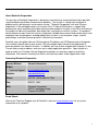
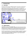
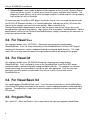
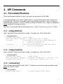
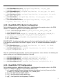
SLX200 API User Manual
isoLynx™ SLX200 API User Manual
isoLynx™ SLX200 API User Manual
MA1027 Rev. C—May 2007
The information in this manual has been checked carefully and is believed to be accurate; however, Dataforth assumes
no responsibility for possible inaccuracies or omissions. Specifications are subject to change without notice.
© 2007 Dataforth Corporation. All rights reserved.
isoLynx is a trademark of Dataforth Corporation.
Microsoft, Windows, Windows XP, Visual Studio, Visual C++, Visual Basic, and Visual C# are trademarks or registered
trademarks of Microsoft Corporation.
Revision History:
Revision
A
B
C
Date
11/16/06
1/18/07
5/2/07
Author
R Lampron
R Lampron
R Lampron
Description of Changes
Initial release
Updated to support Visual Basic 6 applications
Added SuitcaseDemo example program
i
isoLynx SLX200 API User Manual
ii
Table of Contents
1.
Introduction..................................................................................................................................................... 1
1.1.
Overview................................................................................................................................................. 1
1.2.
Helpful Notes .......................................................................................................................................... 1
1.3.
For Visual Basic Users............................................................................................................................ 2
1.4.
Files Required to Use the isoLynx API .................................................................................................. 2
2. Terms You Should Know ............................................................................................................................... 3
2.1.
Ports and Devices.................................................................................................................................... 3
2.2.
Channel Numbers.................................................................................................................................... 3
3. Example Programs .......................................................................................................................................... 5
3.1.
For Visual Basic.NET............................................................................................................................. 5
3.2.
For Visual C++ ....................................................................................................................................... 6
3.3.
For Visual C#.......................................................................................................................................... 6
3.4.
For Visual Basic 6.0................................................................................................................................ 6
3.5.
Program Flow.......................................................................................................................................... 6
4. API Commands............................................................................................................................................... 7
4.1.
Port-related Routines .............................................................................................................................. 7
4.1.1.
slxOpenRtuPort() ............................................................................................................................ 7
4.1.2.
slxOpenTcpPort()............................................................................................................................ 7
4.1.3.
slxClosePort() ................................................................................................................................. 7
4.2.
Device-Related Routines ........................................................................................................................ 8
4.2.1.
slxOpenDev().................................................................................................................................. 8
4.2.2.
slxCloseDev() ................................................................................................................................. 8
4.3.
Configuration Routines........................................................................................................................... 8
4.3.1.
Read Device Information................................................................................................................ 8
4.3.2.
Read/Write RTU (Serial) Configuration......................................................................................... 9
4.3.3.
Read/Write TCP Configuration ...................................................................................................... 9
4.3.4.
Read/Write Analog Channel Configuration.................................................................................. 10
4.3.5.
Digital Channel Configuration...................................................................................................... 11
4.3.6.
Digital Panel Configuration .......................................................................................................... 11
4.4.
Read/Write Analog/Digital Data Routines ........................................................................................... 11
4.5.
User-Defined Scan Routines................................................................................................................. 12
4.5.1.
User-Defined Scan Setup.............................................................................................................. 12
4.5.2.
User-Defined Scan Actions........................................................................................................... 13
4.6.
Other Routines ...................................................................................................................................... 13
4.6.1.
Miscellaneous Status and Control................................................................................................. 13
4.6.2.
Read/Write User Data ................................................................................................................... 14
Appendix A: Error Code Listing.......................................................................................................................... 15
Appendix B: Some Troubleshooting Tips ........................................................................................................... 19
iii
isoLynx SLX200 API User Manual
iv
About Dataforth Corporation
“Our passion at Dataforth Corporation is designing, manufacturing, and marketing the best possible
signal conditioning and data communication products. Our mission is setting new standards of
product quality, performance, and customer service.” Dataforth Corporation, with over 20 years
experience, is the worldwide leader in Instrument Class™ Industrial Electronics—rugged, high
performance signal conditioning and data communication products that play a vital role in maintaining
the integrity of industrial automation, data acquisition, and quality assurance systems. Our products
directly connect to most industrial sensors and protect valuable measurement and control signals and
equipment from the dangerous and degrading effects of noise, transient power surges, internal
ground loops, and other hazards present in industrial environments.
Dataforth spans the globe with over 50 International Distributors and US Representative Companies.
Our customers benefit from a team of over 130 sales people highly trained in the application of
precision products for industrial markets. In addition, we have a team of application engineers in our
Tucson factory ready to address and solve any in-depth application questions. Upon receipt of a
quote or order, our Customer Service Department provides fast one-day response of delivery
information. We maintain inventory that allows small quantity orders to be shipped from stock.
Contacting Dataforth Corporation
Contact Method
Contact Information
E-Mail:
Technical Support
[email protected]
Website:
www.dataforth.com
Phone:
520 704 1404 or 800 444 7644
Fax:
520 741 1404
Mail:
Dataforth Corporation
3331 E. Hemisphere Loop
Tucson, AZ 85706
Errata Sheets
Refer to the Technical Support area of Dataforth’s web site (www.dataforth.com) for any errata
information on this product.
v
isoLynx SLX200 API User Manual
vi
1. Introduction
1.1. Overview
This manual describes the isoLynx SLX200 API, which allows a user to access the functions of the
SLX200 from a user-written program, as shown in Figure 1.1. The functions are contained in the
dynamic link library slxcom.dll (or slxcom_stdcall.dll for Visual Basic 6). A user-written C/C++
program can link in the slxcom.lib import library and have direct access to all the API functions in the
DLL. Visual Basic.NET and C#.NET programs can use the isoLynx class in the files isoLynx.vb (for
VB.NET) and isoLynx.cs (for C#.NET). VB 6.0 requires its own version of the DLL because of its
calling convention. The sample programs can be a good starting point for your own application.
VB.NET
Program
C/C++
Program
workstation
isoLynx.vb
slxcom.h
slxcom.lib
C#.NET
Program
isoLynx.cs
slxcom.dll
slxcom_stdcall.dll
Serial or Ethernet
connection
SLX200
VB 6.0
Program
Figure 1.1 SLX200 API block diagram
1.2. Helpful Notes
PLEASE NOTE: YOU WILL SAVE YOURSELF TIME if you take a few minutes up front and read
sections 1 and 2 of this manual. This document is somewhat “thin” because the routines are mostly
self-explanatory when used in conjunction with the SLX200 Software User Manual. This manual is on
the CD that ships with the SLX200, and is also available by download from the Dataforth web site.
This Software User Manual is referenced throughout this document, and is abbreviated “SUM”.
The API has more than 50 functions, which may seem intimidating, but most applications will only use
9 of them. (The other functions are for user-defined scans and isoLynx configuration. Configuration
is more easily done via the SlxConfig program, supplied on the CD.) These 9 most-used routines
include five which open/close ports and devices (see sections 4.1 and 4.2), and the four which
read/write analog and digital data (see section 4.4).
1
isoLynx SLX200 API User Manual
All API functions return an integer error code; zero means success. Non-zero values are briefly
documented in Appendix A: Error Codes.
No example function calls are shown in this manual; however, every API function has an example of
usage in the VB.NET example programs, and the nine most-common functions also have examples
in the C++, and C#.NET, and VB6 programs.
The SUM makes a great number of references to Modbus register addresses. This API makes
knowing the addresses unnecessary; as a matter of fact, no Modbus register addresses are used
anywhere in the API. For example, if you wish to set the default output value for a particular analog
channel, you don’t need to know that the required registers range from address 0x2100 to 0x213F;
instead, you call the appropriate function (slx200ConfigAoDfltOuts(), in this case), and specify the
desired channel number (0 to 63).
1.3. For Visual Basic Users
The documentation of the routines in this manual shows function prototypes in C++ style. If you’re
not sure about what Visual Basic argument type to use, look at the Visual Basic function declarations
in the example programs. For VB.NET, look at the isoLynx class, in the file isoLynx.vb in the project
RoutinesRequiredByExamples. This class contains VB.NET function declarations for all the routines
in the API, along with numerous useful constants. To use the API, you will need to add a reference to
the RoutinesRequiredByExamples project to your project, or else copy the source code from
isoLynx.vb into your project. For VB6, you will place the API function declarations in the module that
is using them; for an example, see the code for the ReadWriteDataForm in the ReadWriteData
example project.
Be aware that VB does not pass arrays properly to a DLL written in C++, but a workaround is to pass
the first array element by reference. Therefore, in calls to the DLL where an array is expected,
specify the first element of the array instead of the array itself. In VB.NET, make certain you use the
exact array type called for by the function declaration in the isoLynx class; for example, the DLL will
not receive the proper data from VB if you use Int16 instead of UInt16, and you may not get a
compiler warning.
1.4. Files Required to Use the isoLynx API
slxcom.dll or slxcom_stdcall.dll – the actual API. This file must be available to your program, by
either being in the same folder or else in the current environment’s PATH.
slxcom.lib – for C/C++ programs. This is an import library for what Microsoft terms “implicit linking” to
the DLL functions. Link this library into your C/C++ program in order to access the API. This
file is not needed if you do the more painful “explicit linking”, in which you make function calls
to explicitly load and unload the DLL and to access the DLL's exported functions. For a
lightweight explanation of the difference between implicit and explicit linking, search MSDN
(msdn.microsoft.com) for “Linking an Executable to a DLL”.
slxcom.h – header file with API function prototypes and useful #defines for C or C++ programs
isoLynx.vb (and .cs) – definition of isoLynx class for VB.NET (and C#.NET) programs
2
2. Terms You Should Know
2.1. Ports and Devices
In the SLX200 API, a “port” represents the means of connection to the isoLynx(es), such as a COM
port or Ethernet connection. A “device” represents an isoLynx SLX200 (except in the special case
where an isoLynx has two Ethernet connectors, and each one is considered a device). To use the
API properly, the following steps must be done by your program, in this order:
1) Open a port using either the slxOpenRtuPort() or slxOpenTcpPort() command, depending on
whether your application is using Modbus RTU (serial line) or Modbus TCP (Ethernet).
2) Open a device using the slxOpenDev() routine, passing it the handle given to you by the “open
port” routine in step 1.
3) Use the slx200…() routines to send data to (and receive data from) the isoLynx.
4) Close the device using the slxCloseDev() routine.
5) Close the port using the slxClosePort() routine.
See the example programs on the CD, which demonstrate how to do these steps.
2.2. Channel Numbers
The SLX200 is a single-board system with optional expansion panels for additional digital and analog
channels. You can calculate a channel number based on the backpanel’s assigned address and the
channel’s position on the backpanel, as illustrated in the annotated block diagram below.
Channel numbers in the API start at zero (for either digital or analog), and go up through the
maximum number available (63 is the highest analog channel using the maximum of three analog
expansion panels, and 127 is the highest digital channel using the maximum of eight digital panels).
Each panel, whether analog or digital, may contain up to 16 channels. The exception is the main
(base) SLX200 panel, which has only 12 channels, numbered 0-11. A fully populated SLX200
system is shown below in Figure 2.1.
3
isoLynx SLX200 API User Manual
Jumpers on all J1
positions make this
digital panel 0; digital
channels 0-15.
Analog
channels 0-11
Jumpers on J1 pins 34 and 5-6 make this
digital panel 1; digital
channels 16-31.
A jumper across E1/E2
position 1 makes this
expansion panel 1;
analog channels 16-31.
A jumper across E1/E2
position 2 makes this
expansion panel 2;
analog channels 32-47.
A jumper across E1/E2
position 3 makes this
expansion panel 3;
analog channels 48-63.
No jumpers (or open)
on all J1 pins make this
digital panel 7; digital
channels 111-127.
Figure 2.1 SLX200 channel numbers
Perhaps the easiest way to figure channel numbers is to think in hexadecimal. Consider the high
nybble of the single-byte channel number to be the panel number, and the low nybble to be the
channel slot. For example, channel 0x41 refers to panel 4, slot 1 (the second slot from the left).
Other examples are shown in Figure 2.2 below. The “0x” indicates hexadecimal; 0x27 is decimal 39,
and 0x0A is decimal 10. In VB, a hexadecimal number is indicated with the “&H” prefix.
Channel numbers:
0x27 0x0A
panel #2
Figure 2.2 SLX200 channel number examples
4
slot #7
base unit
(panel 0)
slot #10
3. Example Programs
A number of example programs are included on the CD as starting points for your own application,
one each for Visual C++.NET, Visual C#.NET, VB6, and several for VB.NET. Except for the VB6
example and the VB.NET SuitcaseDemo example, they are all console-based so as to not complicate
the code, but the same code will work in a Windows app; you would just use MsgBoxes or text box
controls on a Windows form to display the information.
3.1. For Visual Basic.NET
One solution exists (named SLX200 VB Examples), containing five example projects, each of which
contain a reference to a sixth project (a class library) named RoutinesRequiredByExamples, as
shown in figure 3.1). SimplestExample may be the best one to start with; then move up to the
ReadWriteData project. Note that for all projects, you must edit the openProtocol() routine in
RoutinesRequiredByExamples to match your communications setup.
SimplestExample
SLX200 VB Examples solution
ReadWriteData
ChannelConfig
references to
UserDefinedScan
RoutinesRequiredByExamples
• openProtocol()
• closeProtocol()
• isoLynx class
LessUsedRoutines
SuitcaseDemo
Figure 3.1 Visual Basic.NET example projects
Brief project descriptions:
1) RoutinesRequiredByExamples—class library containing the isoLynx class (needed by any
Visual Basic project accessing the API) and the OpenCloseProtocol module, which shows how
to open and close the port and device used in communicating with the isoLynx. All the other
projects except for SimplestExample use this OpenCloseProtocol module.
2) SimplestExample—a stripped-down version of the ReadWriteData project, containing only the
bare essentials for opening communication, reading/writing analog channels, and closing
communication. Entire file is about 21 lines of code (plus comments).
3) ReadWriteData—example of reading/writing analog and digital channels.
4) ChannelConfig—an example of configuring analog channel states, default outputs, average
weights, and digital channel states and default outputs.
5) UserDefinedScan—shows how to use the API routines to define and execute a user-defined
scan of channels.
6) LessUsedRoutines—contains example routines for reading device information,
reading/writing the RTU and TCP configuration, the miscellaneous status and control routines,
reading/writing user data, and bypassing the digital panels.
5
isoLynx SLX200 API User Manual
7) SuitcaseDemo—source code for demonstration program for the so-called “Suitcase Demos”,
which are isoLynx systems in a black case (hence the name), available from Dataforth. The
program will work with any isoLynx with the proper modules installed (and will start up properly
even without an isoLynx attached).
To create your own Visual Basic.NET project, the easiest way to start is to create the project under
the SLX200 VB Examples solution as a Console Application, and copy one of the .VB source files
(closest to the functions you want) to the new project. Add a reference to the
RoutinesRequiredByExamples project (or else copy the source code for the isoLynx class and
desired routines right out of that project). Copy slxcom.dll to your project’s bin\debug folder. Edit the
openProtocol() routine (in the RoutinesRequiredByExamples project) according to the comments to
match your communication setup.
3.2. For Visual C++
One example solution exists (SLX200 C++ Examples), containing one sample project
(ReadWriteData). It has the same functionality as the ReadWriteData Visual Basic.NET project
mentioned in the previous section, reading/writing both analog and digital channels. The single
source file has a large comment block at the top, explaining how to get going with the project.
3.3. For Visual C#
One example solution exists (SLX200 C# Examples), containing one sample project
(ReadWriteData). It has functionality similar to the ReadWriteData Visual Basic.NET project
mentioned earlier, reading/writing both analog and digital channels. This program has not been
tested exhaustively, but is provided as a starter for your own application. Only the nine most
commonly used API routines are declared in the isoLynx.cs class file and then used in
ReadWriteData.cs.
3.4. For Visual Basic 6.0
One sample project (ReadWriteData) exists. It has the same functionality as the ReadWriteData
Visual Basic.NET project mentioned in the previous section, reading/writing both analog and digital
channels. The project has a single form, containing code to invoke the nine most commonly used
API routines.
3.5. Program Flow
See section 2.1 (“Ports and Devices”) for an overview of the steps your program should follow.
6
4. API Commands
4.1. Port-related Routines
These routines open and close the “port” (the means of connection to the SLX200).
In the following routines, the “hPort”, or port handle, is a unique 32-bit identifier which specifies the
port being used. The hPort is initialized by either of the port-opening routines, and is used later by
the device-opening routines. The user should not change the handle’s value. A port must be opened
before making the call to open a device.
Note that in Visual Studio 2005 (for 32-bit processors), a “long” is the same size as an “int”, 32 bits.
4.1.1. slxOpenRtuPort()
Opens specified RTU port and initializes handle. If the open fails, “hPort” will be NULL.
int slxOpenRtuPort(
unsigned long *hPort, // port handle
const char *const portName, // port name, such as "COM1"
int baud,
// baud (must be one of the values #defined in
//
slxcom.h or isoLynx.vb,
//
such as SLX_BR_19200)
int parity )
// parity (must be one of the #defined values,
//
such as SLX_PAR_EVEN)
4.1.2. slxOpenTcpPort()
Opens specified TCP port and initializes handle. If the open fails, “hPort” will be NULL.
int slxOpenTcpPort(
unsigned long *hPort,
const char *const hostName,
unsigned short portNo )
// port handle
// isoLynx IP addr (e.g., "192.168.0.502")
// isoLynx port number, such as 502
4.1.3. slxClosePort()
Closes the port represented by handle “hPort”. All devices connected to the port should be closed
before this routine is called.
int slxClosePort(
unsigned long hPort )
// handle of port to be closed
7
isoLynx SLX200 API User Manual
4.2. Device-Related Routines
4.2.1. slxOpenDev()
Creates a device object (which represents an isoLynx) and connects it to a port.
int slxOpenDev(
unsigned long *hDevice,
// device handle
unsigned char id,
// only meaningful when used with an RTU port,
//
and indicates the slave ID
unsigned int hPort ) // port handle returned from one of the
//
port-opening routines above
4.2.2. slxCloseDev()
Close device object associated with device handle “hDevice”. Should be done when all processing is
complete, but before the associated port is closed.
int slxCloseDev( unsigned long hDevice );
4.3. Configuration Routines
Note that the values in all capital letters are #defines from the header file slxcom.h. (The values may
also be found in the Software User Manual; this manual is frequently referred to in this section, and is
abbreviated as SUM.) The routines below are grouped by functionality; each group is preceded by a
blurb which discusses the arguments. All of the routines take a first argument “hDevice”, or device
handle, the 32-bit unique integer that identifies the device. The hDevice is returned from the
slxOpenDev( ) function, and should not be altered by the user. The return value of each routine will
be zero if no error occurred, or else one of the values in slxcom.h (these values are also repeated in
this document).
4.3.1. Read Device Information
For the following routines, additional information is available about the register values in the SUM
section 12.1. These routines remove the upper byte of each word (which is zero anyway) in order to
produce a normal null-terminated character string in the “str” buffer. The arguments are defined as
follows:
1) hDevice – device handle
2) pan_type – either PT_ANALOG or PT_DIGITAL. Must be PT_ANALOG for
slx200ReadCommBrdFwRev().
3) panel – panel number (although required, this argument is ignored when pan_type is
PT_ANALOG and is also currently ignored by slx200ReadCommBrdFwRev(); digital panels
are numbered starting at 0)
4) str – character buffer to store retrieved data in; should be at least 17 bytes in length
5) sz – size of “str” buffer (should be at least 17)
8
int slx200ReadManufacturer( unsigned long hDevice, int pan_type,
int panel, char *str, int sz );
int slx200ReadModelNum( unsigned long hDevice, int pan_type, int panel,
char *str, int sz );
int slx200ReadSerialNum( unsigned long hDevice, int pan_type, int panel,
char *str, int sz );
int slx200ReadFwRev( unsigned long hDevice, int pan_type, int panel,
char *str, int sz );
int slx200ReadCommBrdFwRev( unsigned long hDevice, int pan_type,
int panel, char *str, int sz );
4.3.2. Read/Write RTU (Serial) Configuration
For the following routines, additional information is available about the register values in the SUM
section 3.4. Additional arguments in the following routines are:
1) serif – serial interface type, either SLX_SERIF_RS232, SLX_SERIF_RS485_2, or
SLX_SERIF_RS485_4.
2) baud – baud rate, either SLX_BR_1200, SLX_BR_2400, SLX_BR_4800, SLX_BR_9600,
SLX_BR_19200, SLX_BR_38400, SLX_BR_57600, or SLX_BR_115200.
3) par – parity, either SLX_PAR_NONE, SLX_PAR_ODD, or SLX_PAR_EVEN.
4) id – slave ID number.
PLEASE NOTE: the following function preserves the least significant four bits of the “id” variable, so
if you want the actual value of the Slave ID register, set the “id” variable to zero before calling this
function.
int slx200ReadRtuParms( unsigned long hDevice, int *serif, int *baud,
int *par, unsigned char *id );
int slx200ConfigRtuParms( unsigned long hDevice, int serif, int baud,
int par, unsigned char id );
Note that slx200ConfigRtuParms() specifies all the parameters at one, whereas the following four
routines allow you to set individual parameters if desired.
int
int
int
int
slx200ConfigRtuSerIf( unsigned long hDevice, int serif );
slx200ConfigRtuBaud( unsigned long hDevice, int baud );
slx200ConfigRtuParity( unsigned long hDevice, int par );
slx200ConfigRtuSlvId( unsigned long hDevice, unsigned char id );
4.3.3. Read/Write TCP Configuration
For the following routines, additional information is available about the register values in the SUM
section 3.5. Additional arguments in the following routines are:
1) sel – specifies which Ethernet interface to use on the isoLynx (most only have one), either
SLX200_TCP_PARMS_PRI or SLX200_TCP_PARMS_SEC.
2) ip[ ] – four-byte buffer to hold IP address
3) sn[ ] – four-byte buffer to hold subnet mask
4) gw[ ] – four-byte buffer to hold gateway IP address
9
isoLynx SLX200 API User Manual
5) kato – keepalive timeout
6) tcp_port – port number
7) mac[ ] – six-byte buffer to hold MAC address
int slx200ReadTcpParms( unsigned long hDevice, int sel,
unsigned char ip[], unsigned char sn[], unsigned char gw[],
unsigned short *kato, unsigned short* tcp_port, unsigned char mac[] );
int slx200ConfigTcpParms( unsigned long hDevice, int sel,
const unsigned char ip[],const unsigned char sn[],
const unsigned char gw[], unsigned short kato );
Note that slx200ConfigTcpParms () specifies all the parameters at once, whereas each of the
next four routines allow you to set an individual parameter.
int slx200ConfigTcpIpAddr( unsigned long hDevice, int sel,
const unsigned char ip[] );
int slx200ConfigTcpSnMask( unsigned long hDevice, int sel,
const unsigned char sn[] );
int slx200ConfigTcpGateway( unsigned long hDevice, int sel,
const unsigned char gw[] );
int slx200ConfigTcpKato( unsigned long hDevice, int sel,
unsigned short kato );
4.3.4. Read/Write Analog Channel Configuration
For the following routines, additional information is available about the register values in the SUM
section 4. Additional arguments in the following routines are:
1) chan – beginning channel to work with (0-63 for analog channels on the SLX200)
2) data[ ] – buffer that holds the values read from or written to the SLX200.
3) qty – number of values to be read or written. (chan + qty) should not exceed 64.
In the following two routines, each element of data[] should be one of the values
SLX200_ACS_VACANT, SLX200_ACS_INPUT, or SLX200_ACS_OUTPUT.
int slx200ReadAnaChanStates( unsigned long hDevice, unsigned char chan,
short data[], int qty );
int slx200ConfigAnaChanStates( unsigned long hDevice, unsigned char chan,
const short data[], int qty );
Note that in the following two routines, channels assigned as inputs or vacant will always have
0x0000 as their default outputs, regardless of what you may attempt to set them to.
int slx200ReadAoDfltOuts( unsigned long hDevice, unsigned char chan,
short data[], int qty );
int slx200ConfigAoDfltOuts( unsigned long hDevice, unsigned char chan,
const short data[], int qty );
Note that in the following routines, the “average weight” must be (or else will be forcibly rounded
down to) a power of 2, as indicated in Table 4.1 of the SUM. Also, the corresponding channel must
be an input, or the value will be ignored (left at zero).
int slx200ReadAiAvgWgts( unsigned long hDevice, unsigned char chan,
10
unsigned short data[], int qty );
int slx200ConfigAiAvgWgts( unsigned long hDevice, unsigned char chan,
const unsigned short data[], int qty );
4.3.5. Digital Channel Configuration
For the following routines, additional information is available about the register values in the SUM
section 5. Additional arguments in the following routines are:
1) chan – beginning channel to work with (0-127 for digital channels on the SLX200)
2) data[ ] – buffer that holds the values read from or written to the SLX200.
3) qty – number of values to be read or written
In the following two routines, each element of data[] should be one of the values
SLX200_DCS_VACANT, SLX200_DCS_INPUT, or SLX200_DCS_OUTPUT.
int slx200ReadDigChanStates( unsigned long hDevice, unsigned char chan,
short data[], int qty );
int slx200ConfigDigChanStates( unsigned long hDevice, unsigned char chan,
const short data[], int qty );
int slx200ReadDoDfltOuts( unsigned long hDevice, unsigned char chan,
int data[], int qty );
int slx200ConfigDoDfltOuts( unsigned long hDevice, unsigned char chan,
const int data[], int qty );
4.3.6. Digital Panel Configuration
For the following routines, additional information is available about the register values in the SUM
section 6 and 13.2. Additional arguments in the following routines are:
1) panel – panel number
2) rst_type – type of reset; may be SLX200_RST_STD (standard) or SLX200_RST_TO_DFLT
(reset-to-default)
3) byp – specifies if panel is bypassed; may be SLX200_DP_NOT_BYPASSED or
SLX200_DP_BYPASSED
int slx200ResetDigPanel( unsigned long hDevice, unsigned char panel,
int rst_type );
int slx200SetDigPanelBypass( unsigned long hDevice, unsigned char panel,
int byp );
4.4. Read/Write Analog/Digital Data Routines
For the following routines, additional information is available about the register values in the SUM
sections 8-10. In each of the following routines, the arguments are defined as follows:
1) hDevice – device handle
2) type – either SLX200_DT_CUR (current value), SLX200_DT_AVG (average value),
SLX200_DT_MAX, or SLX200_DT_MIN. For the two “DigitalData” routines, the type must be
SLX200_DT_CUR.
11
isoLynx SLX200 API User Manual
3) chan – channel number
4) data[ ] – array of 16-bit values to either read from or write to the isoLynx
5) qty – number of 16-bit values to transfer
The first two routines are for the analog inputs/outputs, and the second two are for the digital
inputs/outputs.
int slx200ReadAnalogCounts( unsigned long hDevice, int type,
unsigned char chan, short data[], int qty );
int slx200WriteAnalogCounts( unsigned long hDevice, int type,
unsigned char chan, const short data[], int qty );
int slx200ReadDigitalData( unsigned long hDevice, int type,
unsigned char chan, int data[], int qty );
int slx200WriteDigitalData( unsigned long hDevice, int type,
unsigned char chan, const int data[], int qty );
4.5. User-Defined Scan Routines
4.5.1. User-Defined Scan Setup
For a user-defined scan, first determine which channels you want to scan, and in what order. Build
your scan list “on paper”. Then write your program to perform the following steps, in the order
indicated. More detailed information is available in the SUM, sections 7.2 and 8.2.
1) Call slx200SetScanMode() to set the scan mode to User.
2) Call slx200ConfigUserScanParms() to configure the scan list (that you designed above),
interval (time between complete scans through the scan list), and count (number of times to
run through the scan list). The API will add the end-of-list specifier onto the end of the scan list
for you.
3) Call slx200StartUserScan() to begin the scan.
4) Poll the Scan Control Register using slx200ReadScanControl() to see if the scan is done,
and how many words are available.
5) When the scan is done (or even while it is still running), read as many words as desired (up to
the quantity available) using slx200ReadScanDataReg().
6) If you encounter a transmission error reading the data, you can restore the words just read
from the buffer by using slx200WriteScanDataReg(). Then retry the call to
slx200ReadScanDataReg().
For the following routines, additional information is available about the register values in the SUM
section 7. Additional arguments in the following routines are:
1) scan_mode – specifies scan mode, either SLX200_SM_CONT or SLX200_SM_USER (see SUM
section 7.1 for an explanation of scan modes)
2) list[ ] – list of up to 64 analog input channel IDs (first channel is channel 0). Note that unlike
the Modbus call specified in the SUM (section 7.2), the list is not terminated by an end-of-list
indicator (0xFF). Instead the following argument indicates the list size.
3) list_sz – number of valid input channel IDs in the list[ ]
4) intv – scan interval (number of milliseconds between complete scans)
5) cnt – number of times to scan all entries in the Scan List
12
int slx200ReadScanMode( unsigned long hDevice, int *scan_mode );
int slx200SetScanMode( unsigned long hDevice, int scan_mode );
Please note that if you invoke the following routine without having first configured the scan
parameters, it may fail with a SLX_EC_ILLEGAL_RESP error code.
int slx200ReadUserScanParms(
// read all scan parameters
unsigned long hDevice, unsigned char list[], int *list_sz,
unsigned short *intv, unsigned short *cnt );
In the following routine, you do not need to specify the end-of-list indicator in your scan list; the API
will add the indicator for you. Do not include the end-of-list indicator in your list_sz quantity.
int slx200ConfigUserScanParms(
// set all scan parameters
unsigned long hDevice, const unsigned char list[], int list_sz,
unsigned short intv, unsigned short cnt );
Note that slx200ConfigUserScanParms() specifies all the parameters at one, whereas the next
three routines allow you to set individual parameters if desired.
int slx200ConfigUserScanList( unsigned long hDevice,
const unsigned char list[], int list_sz );
int slx200ConfigUserScanInt( unsigned long hDevice, unsigned short intv );
int slx200ConfigUserScanCnt( unsigned long hDevice, unsigned short cnt );
4.5.2. User-Defined Scan Actions
For the following routines, additional information is available about the register values in the SUM
section 8.2. Additional arguments in the following routines are:
1) data[ ] – buffer to receive data read from scan data register
2) qty – number of 16-bit values to read
3) scan_complete – indicates scan status; 0 = in progress, 1 = complete
4) data_cnt – number of 16-bit values in Scan Data Buffer
int
int
int
int
int
slx200ReadScanDataReg( unsigned long hDevice, short data[], int qty );
slx200WriteScanDataReg( unsigned long hDevice );
slx200StartUserScan( unsigned long hDevice );
slx200StopUserScan( unsigned long hDevice );
slx200ReadScanControl( unsigned long hDevice, int *scan_complete,
unsigned short *data_cnt );
4.6. Other Routines
4.6.1. Miscellaneous Status and Control
For the following routines, additional information is available about the register values in the SUM
section 13. Additional arguments in the following routines are:
1) status – status returned from isoLynx (SUM section 13.1)
13
isoLynx SLX200 API User Manual
2) rst_type – type of firmware reset (SUM section 13.2). Value is either SLX200_RST_STD or
SLX200_RST_TO_DFLT from slxcom.h.
3) ec – error code from isoLynx (SUM section 13.3)
4) ei – error information register from isoLynx (SUM section 13.3)
5) adc_in – input source for the ADC (for factory use; see SUM section 13.4)
int slx200ReadStatus( unsigned long hDevice, short *status );
Note on the following routine: the digital panels can be individually reset using the
slx200ResetDigPanel() routine later in this document.
int slx200Reset( unsigned long hDevice, int rst_type );
int slx200ReadErrorRegisters( unsigned long hDevice, short *ec,
short *ei );
The following routine is for factory use and should not be invoked under normal circumstances.
int slx200SetAdcInput( unsigned long hDevice, int adc_in );
4.6.2. Read/Write User Data
For the following routines, additional information is available about the register values in the SUM
section 8.2. Additional arguments in the following routines are:
1) addr – simplified address to read from or write to (valid values are 0 to 255)
2) data[ ] – buffer holding data to be written or to receive data read. This goes without saying, but
be sure the buffer is large enough to hold the number of 16-bit values specified in “qty”.
3) qty – number of 16-bit values to be read or written. (addr + qty) cannot exceed 255.
int slx200ReadUserData( unsigned long hDevice, unsigned short addr,
short data[], int qty );
int slx200WriteUserData( unsigned long hDevice, unsigned short addr,
const short data[], int qty );
14
Appendix A: Error Code Listing
These error codes may be returned from the routines in the API. “INV” in an error name means
“invalid”. See the next page for the less-common errors 5000-5199.
Modbus Port Error Codes (5200-5299)
MBPORT_EC_SUCCESS
MBPORT_EC_PORT_NOT_OPEN
MBPORT_EC_INV_PARITY
MBPORT_EC_MEM_ALLOC
0
5200
5201
5202
General SLX Device Error Codes (5300-5399)
SLX_EC_SUCCESS
SLX_EC_DEV_NOT_OPEN
SLX_EC_MEM_ALLOC
SLX_EC_ILLEGAL_ARG
0
5300
5301
5302
// some possible causes are invalid channel
//
state or channel type specified, or
//
invalid array size specified, or
//
qty < 1
SLX_EC_ILLEGAL_RESP 5303
SLX_EC_INV_FLD_SZ
5304
SLX_EC_INV_SERIF
5305
SLX_EC_INV_BAUD
5306
SLX_EC_INV_PARITY
5307
SLX_EC_INV_DEV_HANDLE
5308
SLX_EC_INV_PORT_HANDLE
5309
SLX200 Device Error Codes (5400-5499)
SLX200_EC_SUCCESS
SLX200_EC_INV_TCPPARMS
SLX200_EC_INV_PANTYPE
SLX200_EC_INV_DATATYPE
SLX200_EC_INV_RSTTYPE
SLX200_EC_INV_SCANMODE
SLX200_EC_INV_ADCIN
SLX200_EC_INV_DIGBYP
SLX200_EC_INV_PANEL
SLX200_EC_INV_CHAN
SLX200_EC_INV_CHAN_QTY
SLX200_EC_INV_UDATA_ADDR
SLX200_EC_INV_UDATA_QTY
SLX200_EC_INV_QTY
0
5400
5401
5402
5403
5404
5405
5406
5407
5408
5409
5410
5411
5412
// datatype not cur, avg, max, or min
// channel + qty > max # of channels
// qty < 1
15
isoLynx SLX200 API User Manual
SLX Com Library Error Codes (5500-5599)
SLXCOM_EC_SUCCESS
SLXCOM_EC_MEM_ALLOC
SLXCOM_EC_INV_QTY
SLXCOM_EC_INV_FLD_SZ
0
5500
5501
5502
FieldTalk Library Error Codes (5000-5199)
The SLX200 API uses the FieldTalk library for Modbus communications. The following errors are not
#defined in slxcom.h, but are taken from the FieldTalk library documentation.
Errors of this class typically indicate a programming mistake.
FTALK_ILLEGAL_ARGUMENT_ERROR
5001 // Illegal argument error
FTALK_ILLEGAL_STATE_ERROR
5002 // This return code is returned by
// all functions if the protocol has not been opened succesfully yet.
FTALK_EVALUATION_EXPIRED
5003 // Evaluation expired
FTALK_NO_DATA_TABLE_ERROR
5004 // No data table configured
FTALK_ILLEGAL_SLAVE_ADDRESS
5005 // Slave address 0 illegal for
//
serial protocols.
FieldTalk Fatal I/O Errors: Errors of this class signal a problem in conjunction with the I/O system. If
errors of this class occur, the operation must be aborted and the device/port closed.
FTALK_IO_ERROR_CLASS
5064
// I/O error class
FTALK_IO_ERROR
5065
// underlying I/O system reported error
FTALK_OPEN_ERR
5066
// Port or socket open error
FTALK_PORT_ALREADY_OPEN 5067
// Serial port already open
FTALK_TCPIP_CONNECT_ERR 5068
// Typically this error occurs when a
// host does not exist on the network or the IP address is wrong.
// The remote host must also listen on the appropriate port.
FTALK_CONNECTION_WAS_CLOSED
5069 // Remote peer closed TCP/IP connection
FTALK_SOCKET_LIB_ERROR
5070
// Socket library DLL not found
FTALK_PORT_ALREADY_BOUND 5071
// TCP port already bound
FTALK_LISTEN_FAILED
5072
// Listen failed
FTALK_FILEDES_EXCEEDED
5073
// File descriptors exceeded
FTALK_PORT_NO_ACCESS
5074
// No permission to access serial port
//
or TCP port
FTALK_PORT_NOT_AVAIL
5075
// TCP port not available
FieldTalk Communication Errors: Errors of this class indicate either communication faults or Modbus
exceptions reported by the slave device.
FTALK_BUS_PROTOCOL_ERROR_CLASS 5128
// Fieldbus protocol error class
FTALK_CHECKSUM_ERROR
5129
// A poor data link typically
// causes this error and the next one.
FTALK_INVALID_FRAME_ERROR
5130
// Invalid frame error
FTALK_INVALID_REPLY_ERROR
5131
// Invalid reply error
FTALK_REPLY_TIMEOUT_ERROR
5132
// This can occur if the slave
// device does not reply in time or does not reply at all. A wrong
// unit adress will also cause this error.
16
FTALK_SEND_TIMEOUT_ERROR
5133
// This can only occur if the
// handshake lines are not properly set.
FTALK_MBUS_EXCEPTION_RESPONSE 5160
// Modbus exception response
// received from slave device.
FTALK_MBUS_ILLEGAL_FUNCTION_RESPONSE 5161 // Sent by a slave device
// instead of a normal response message if a master sent a Modbus
// function which is not supported by the slave device.
FTALK_MBUS_ILLEGAL_ADDRESS_RESPONSE 5162 // Illegal Data Address
//
exception response
FTALK_MBUS_ILLEGAL_VALUE_RESPONSE
5163 // Illegal Data Value exception
//
response
FTALK_MBUS_SLAVE_FAILURE_RESPONSE
5164 // Slave Device Failure
// exception response; one cause can be from writing to a digital
// channel that is vacant or is an input.
17
isoLynx SLX200 API User Manual
18
Appendix B: Some Troubleshooting Tips
If you are reading all zeroes from your analog channels, but expected to see some non-zero values,
the isoLynx may be in User-Defined Scan mode.
Note that you should open a port before opening the associated device, and at the end of your
program, you must close the device before closing the port. I.e., the port should be opened first and
closed last.
If unexpected or unusual things are happening and you are using Visual Basic, see section 2.3 of this
manual for warnings about arrays and DLLs.
If you can’t communicate at all with the isoLynx, see if you can communicate with it using the
SlxConfig (isoLynx Configuration) program supplied on the CD. If so, compare the communication
settings in SlxConfig with the settings in your program. Remember that most serial ports can’t be
opened by more than one program at a time, however.
The SlxConfig program is a handy tool to use to double-check your program. If you’re not seeing
what you expect from a channel, using the Quick Channel View window of SlxConfig to see what
values it’s reading from the isoLynx. SlxConfig will also show you quickly whether a channel slot is
configured as vacant, etc.
Note that the DLL routines that accept arrays assume your arrays are at least as large as you specify
in the “quantity” argument. If your array is too small to receive the number of values specified in your
“quantity” argument, the routine will write off the end of the array, corrupting memory or worse.
If your program is Visual C++, and you receive the error message when starting your application:
“This application has failed to start because MSVCR80D.dll was not found. Re-installing the
application may fix the problem." This is due to a known VS2005 problem. The cause is that the
manifest resource file "Debug\xyz.exe.embed.manifest.res" is generated BEFORE its source file.
(Just check the build log.) Removing the .res file and rebuilding cures the problem.
19