1
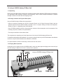
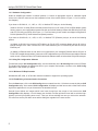
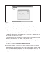
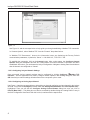
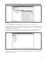
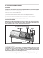
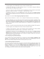
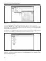
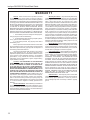
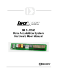
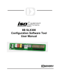
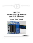
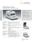
SLX200/101
Quick Start Guide
Table of Contents
1.0 isoLynx SLX200 Analog I/O Base Unit ........................................................................................................ 1
1.1 Unpacking ............................................................................................................................................. 1
1.2 Package Contents and Physical Description ........................................................................................ 1
1.3 Verifying Basic Operation ..................................................................................................................... 1
1.3.1 Hardware Configuration ............................................................................................................... 2
1.3.2 Using PC Configuration Software ................................................................................................ 2
2.0 isoLynx SLX101 Digital I/O Backpanel ........................................................................................................ 7
2.1 Unpacking ............................................................................................................................................. 7
2.2 Package Contents and Physical Description ........................................................................................ 7
2.3 Verifying Basic Operation ..................................................................................................................... 7
2.3.1 Hardware Configuration ............................................................................................................... 7
2.3.2 Using PC Configuration Software ................................................................................................ 8
isoLynxTM SLX200/101 Quick Start Guide
MA1023 Rev. A - August 2005
© 2005 Dataforth Corporation. All Rights Reserved.
1.0 isoLynx SLX200 Analog I/O Base Unit
1.1 Unpacking
Each isoLynx SLX200 Analog I/O Base Unit is shipped in electro-static discharge (ESD) protective packaging.
Use appropriate ESD protection measures while unpacking. Check visually for physical damage. If physical
damage is noted, file a claim with the shipping carrier.
1.2 Package Contents and Physical Description
isoLynx SLX200 Analog I/O Base Unit comprised of:
• isoLynx Controller (containing one SLX211 Processor Board, one I/O Signal Converter Board, and one
optional Industrial Communication Board) mounted on the 12 channel Analog I/O Base Unit backpanel.
Similar to Figure 1.1 depending upon model ordered.
• One CD-ROM containing isoLynx data acquisition software drivers/examples and documentation files
including: Help files, manuals, and specifications.
• This isoLynx SLX200/101 Quick Start Guide.
This completes the unpacking and visual inspection of the isoLynx SLX200 Analog I/O Base Unit.
For detailed configuration and installation in your system, reference the isoLynx SLX200 Hardware User Manual
and/or the isoLynx SLX200 Software User Manual on CD-ROM.
For rapid verification of basic functionality, continue with the next section.
1.3 Verifying Basic Operation
At this point you are ready to insert an SCM5B module, connect an input signal, and apply power to the isoLynx
SLX200 Analog I/O Base Unit in order to verify its basic operation.
isoLynx SLX200 Analog I/O Base Unit
Figure 1.1
1
isoLynx SLX200/101 Quick Start Guide
1.3.1 Hardware Configuration
Install an SCM5B input module in channel position 0. Connect an appropriate sensor or calibration signal
source to the field I/O connectors on the backpanel in front of the module (Refer to Figure 1.1 for I/O connection diagram).
If you have an SLX200-10, -11, -10D, or -11D, i.e. Modbus RTU isoLynx, do the following.
Install an SLX141-xx cable (RJ45 both ends) and an SLX142-x or SLX143-x RJ-45 to DB-9 adapter (either
factory preset or user configurable) between the isoLynx SLX200 Analog I/O Base Unit RS-232 port (RJ-45)
and a PC RS-232 port (DB-9). See Figure 1.1. From the factory, these models are shipped configured for
RS-232 (Modbus RTU), 19200 bits/second (Baud) interface.
If you have an SLX200-20, -21, -20D, or -21D, i.e. Modbus TCP (Ethernet) isoLynx, do one of the following
options.
(a) Obtain an SLX141-Xxx crossover CAT5 cable or an RJ-45 CAT5 crossover adapter and an SLX141-xx
straight through CAT5 cable. Connect the CAT5 cable between your PC’s Ethernet port and the isoLynx
Ethernet port.
(b) Obtain an Ethernet switch or hub which is not connected to your enterprise Ethernet and two SLX141-xx
RJ-45 CAT5 straight through cables. Connect one CAT5 cable between your PC’s Ethernet port and the Ethernet
switch or hub. Connect the other CAT5 cable between the Ethernet switch or hub and the isoLynx Ethernet port.
1.3.2 Using PC Configuration Software
To install the isoLynx SLX Configuration utility, use the install utility in the SLX Config folder on the CD-ROM.
The install utility transfers the appropriate files to your computer and creates a shortcut to the SLX Config
application in the location you desire.
1.3.2.1 Minimum PC Requirements
Windows 98, ME, 2000, or XP and the minimum hardware to support the operating system.
1.3.2.2 Establishing a Communication Connection
From the Start menu, click on the SLX Config shortcut created in section 1.3.2 above to start the isoLynx SLX
Configuration utility. Once started, SLX Configuration will display an initial screen with a View Pane indicating that the application is not yet connected to the attached isoLynx.
Several figures below are images which have been formed from the merger of two screens the SLX
Configuration utility displays. You will always see the Main Tool Bar pull-down menu with a selection highlighted if you hold your pointing arrow over it. Then you will see a dialog box once you click on the selection.
You will never see the pull down menu and the dialog box together in the same screen.
2
Figure 1.2
(1) Click on Connection. Then click on Connect Options… F3.
Clicking on Connect Options… F3, launches the Configure Connect Options dialog box.
(2) At this time, depending on the type of isoLynx you have, follow the instructions in one of the options below.
(2A) If you have an SLX200-10, -11, -10D, or -11D, i.e. Modbus RTU isoLynx, do the following.
Use Figure 1.2 and the text steps below to help guide you through establishing a Modbus RTU connection.
In “Connect Options”, select “Modbus RTU” from the “Protocol” drop-down list-box.
In “Modbus RTU Parameters”, the default COM port is set to 1. If you need to change the COM port,
enter the number of the COM port you are using.
At this time, observe the other information boxes are displaying the Factory Default communication
parameters, in particular, “Slave ID” = 31, “Baudrate” = 19200, and “Parity” = Even.
To establish the connection, click on the Connect button. After a short pause, the Configure Connect
Options dialog box disappears and the SLX Configuration View Pane indicates that a connection has been
established.
Now continue on to section 1.3.2.4 Configuring an Analog Input Channel.
(2B) If you have an SLX200-20, -21, -20D, or -21D, i.e. Modbus TCP (Ethernet) isoLynx, do the following.
For initial configuration, you must connect with a host PC that has network settings compatible with the
isoLynx factory default network settings (IP Address = 192.168.0.215, Subnet Mask = 255.255.255.0, TCP
Port = 502). You may have to temporarily configure your PC’s network settings before connecting to the
isoLynx. Once connected, the isoLynx network settings can be configured to be compatible with your
company network.
3
isoLynx SLX200/101 Quick Start Guide
Figure 1.3
Use Figure 1.3 and the text steps below to help guide you through establishing a Modbus TCP connection.
In “Connect Options”, select “Modbus TCP” from the “Protocol” drop-down list-box.
In “Modbus TCP Parameters”, observe the information boxes are displaying the Factory Default
communication parameters, in particular, “Server” = 192.168.0.215, “TCP Port” = 502.
To establish the connection, click on the Connect button. After a short pause, the Configure Connect
Options dialog box disappears and the SLX Configuration View Pane indicates a connection has been
established. At this time, you can browse the isoLynx configuration. Navigate to Analog Panel 0 and observe
that all channels are configured as “Vacant”.
1.3.2.3 Configuring isoLynx Network Settings
Once connected, isoLynx network settings may be configured by clicking Configure -→ Modbus TCP
Interface… from the application main menu. Configure network options in the resulting dialog box, then click
OK. New isoLynx network settings will take effect on the next power cycle or reset.
1.3.2.4 Configuring an Analog Input Channel
Use Figure 1.4 and the text steps below to help guide you through configuring an input channel in the isoLynx
SLX200. You will see the Configure pull-down menu with Analog Channel States, then Panel 0 (Base Unit)…
highlighted. Then you will see the Configure Analog Channel States dialog box once you click on
Panel 0 (Base Unit)…. This dialog box can also be accessed by double-clicking the “Analog Panel 0” entry in
the SLX Configuration View Pane. With this in mind, continue with the steps below.
4
Figure 1.4
(1) In the Configure Analog Channel States dialog box, select “Input” from the drop-down list-box.
(2) Click the Configure button in the top right corner to send isoLynx its new configuration. After a short
communication pause, the isoLynx SLX200 Base Unit Controller is now configured. The Configure Analog
Channel States dialog box disappears.
(3) At this point, the SLX Configuration utility reverts to the View Pane. Figure 1.5 has the “Analog Configuration
and Panel 0 (Base Unit)” lines expanded to confirm that Channel 0 has been configured as an input.
Figure 1.5
(4) Now that your channel is configured, disconnect by clicking Disconnect…F5 in the Connect drop-down
menu or by pushing the (F5) key.
5
isoLynx SLX200/101 Quick Start Guide
1.3.2.5 Reading an Input Channel
Read the most recent conversion, running average, maximum, and minimum values for analog channel 0 by
reading 4 registers from the zero-based Modbus address 256 (0x0100). If your system uses one-based
addressing, the address is 257 (0x0101).
Use either the Modbus Read Input Registers (function code 4) or the Read Holding Registers (function code 3)
command to perform the read. See the SLX200 Software User Manual for the full register address map.
6
2.0 isoLynx SLX101 Digital I/O Backpanel
2.1 Unpacking
Each isoLynx SLX101 Digital I/O Backpanel is shipped in electro-static discharge (ESD) protective packaging.
Use appropriate ESD protection measures while unpacking. Check visually for physical damage. If physical
damage is noted, file a claim with the shipping carrier.
2.2 Package Contents and Physical Description
• isoLynx SLX101 Digital I/O Backpanel. Similar to Figure 2.1 depending on model ordered.
This completes the unpacking and visual inspection of the isoLynx SLX101 Digital I/O Backpanel.
For rapid verification of basic functionality, continue with the next section.
2.3 Verifying Basic Operation
At this point you are ready to insert an SCMD module, connect an external signal, connect communications to
the isoLynx Analog I/O Base Unit, and apply power to both the isoLynx Analog I/O Base Unit and isoLynx
Digital I/O Backpanel in order to verify the system's basic operation as follows.
isoLynx SLX101 Digital I/O Backpanel
Figure 2.1
2.3.1 Hardware Configuration
Install an SCMD input module in channel position 0. Connect an appropriate discrete digital signal to the field
I/O connectors (note: odd numbered screw terminals are + connection) on the backpanel behind the module.
See Figure 2.1. The isoLynx SLX101 Digital I/O Backpanel will demonstrate basic operation without any
modules installed as long as at least one input channel is configured.
Install one end of an SLX141-xx straight through CAT5 cable into either Digital I/O port, see Figure 2.1. Install
the other end of the cable into the Digital I/O port on the isoLynx SLX200 Analog I/O Base Unit, see Figure 1.1.
7
isoLynx SLX200/101 Quick Start Guide
If you have an SLX200-10, -11, -10D, or -11D, i.e. Modbus RTU isoLynx, do the following.
Install an SLX141-xx cable (RJ45 both ends) and an SLX142-x or SLX143-x RJ-45 to DB-9 adapter (either
factory preset or user configurable) between the isoLynx SLX200 Analog I/O Base Unit RS-232 port (RJ-45)
and a PC RS-232 port (DB-9). See Figure 1.1. From the factory, these models are shipped configured for
RS-232 (Modbus RTU), 19200 bits/second (Baud) interface
If you have an SLX200-20, -21, -20D, or -21D, i.e. Modbus TCP (Ethernet) isoLynx, do one of the following
options.
(a) Obtain an SLX141-Xxx crossover CAT5 cable or an RJ-45 CAT5 crossover adapter and an SLX141-xx
straight through CAT5 cable. Connect the CAT5 cable between your PC’s Ethernet port and the isoLynx
Ethernet port.
(b) Obtain an Ethernet switch or hub which is not connected to your enterprise Ethernet and two SLX141-xx
RJ-45 CAT5 straight through cables. Connect one CAT5 cable between your PC’s Ethernet port and the
Ethernet switch or hub. Connect the other CAT5 cable between the Ethernet switch or hub and the isoLynx
Ethernet port.
Connect a +5VDC 1 Amp (minimum) linear power supply and turn on the power. Observe the +5V LEDs lighting.
Observe the A/D LED blinking with a 50% duty cycle. For location of LEDs, see Figure 1.1.
2.3.2 Using PC Configuration Software
To install the isoLynx SLX Configuration utility, use the install utility in the SLX Config folder on the CD-ROM.
The install utility transfers the appropriate files to your computer and creates a shortcut to the SLX Config
application in the location you desire.
2.3.2.1 Minimum PC Requirements
Windows 98, ME, 2000, or XP and the minimum hardware to support the operating system.
2.3.2.2 Establishing a Communication Connection
From the Start menu, click on the SLX Config shortcut created in section 2.3.2 above to start the isoLynx SLX
Configuration utility. Once started, SLX Configuration will display an initial screen with a View Pane indicating that the application is not yet connected to the attached isoLynx.
Several figures below are images which have been formed from the merger of two screens the SLX
Configuration utility displays. You will always see the Main Tool Bar pull-down menu with a selection highlighted if you hold your pointing arrow over it. Then you will see a dialog box once you click on the selection. You
will never see the pull down menu and the dialog box together in the same screen.
Use Figure 1.2 and the text steps below to help guide you through making a communication connection to the
Modbus isoLynx SLX200/SLX101.
(1) Click on Connection. Then click on Connect Options… F3.
Clicking on Connect Options… F3, launches the Configure Connect Options dialog box.
(2) At this time, depending on the type of isoLynx you have, follow the instructions in one of the options below.
(2A) If you have an SLX200-10, -11, -10D, or -11D, i.e. Modbus RTU isoLynx, do the following.
8
In “Connect Options”, select “Modbus RTU” from the “Protocol” drop-down list-box.
In “Modbus RTU Parameters”, the default COM port is set to 1. If you need to change the COM port,
enter the number of the COM port you are using.
At this time, observe the other information boxes are displaying the Factory Default communication
parameters, in particular, “Slave ID” = 31, “Baudrate” = 19200, and “Parity” = Even.
To establish the connection, click on the Connect button. After a short pause, the Configure Connect
Options dialog box disappears and the SLX Configuration View Pane indicates that a connection has been
established.
Now continue on to section 2.3.2.4 Configuring a Digital Input Channel.
(2B) If you have an SLX200-20, -21, -20D, or -21D, i.e. Modbus TCP (Ethernet) isoLynx, do the following.
For initial configuration, you must connect with a host PC that has network settings compatible with the
isoLynx factory default network settings (IP Address = 192.168.0.215, Subnet Mask = 255.255.255.0, TCP
Port = 502). You may have to temporarily configure your PC’s network settings before connecting to the
isoLynx. Once connected, the isoLynx network settings can be configured to be compatible with your
company network.
Use Figure 1.3 and the text steps below to help guide you through establishing a Modbus TCP connection.
In “Connect Options”, select “Modbus TCP” from the “Protocol” drop-down list-box.
In “Modbus TCP Parameters”, observe the information boxes are displaying the Factory Default
communication parameters, in particular, “Server” = 192.168.0.215, “TCP Port” = 502.
To establish the connection, click on the Connect button. After a short pause, the Configure Connect
Options dialog box disappears and the SLX Configuration View Pane indicates a connection has been
established. At this time, you can browse the isoLynx configuration. Navigate to Digital Panel 0 and observe
that all channels are configured as “Vacant”.
2.3.2.3 Configuring isoLynx Network Settings
Once connected, isoLynx network settings may be configured by clicking Configure -→ Modbus TCP
Interface… from the application main menu. Configure network options in the resulting dialog box, then click
OK. New isoLynx network settings will take effect on the next power cycle or reset.
2.3.2.4 Configuring a Digital Input Channel
Use Figure 2.2 and the text steps below to help guide you through configuring a digital input channel in the
isoLynx SLX200/SLX101. You will see the Configure pull-down menu with Digital Channel States, then
Panel 0… highlighted. Then you will see the Configure Digital Channel States dialog box once you click
on Panel 0…. This dialog box can also be accessed by double-clicking the “Digital Panel 0” entry in the
SLX Configuration View Pane. With this in mind, continue with the steps below.
9
isoLynx SLX200/101 Quick Start Guide
Figure 2.2
(1) In the Configure Digital Channel States dialog box, select “Input” from the drop-down list-box.
(2) Click the Configure button in the top right corner to send isoLynx its new configuration. After a short
communication pause, the isoLynx SLX200 Base Unit Controller is now configured. The Configure Digital
Channel States dialog box disappears.
(3) At this point, the SLX Configuration utility reverts to the View Pane. Figure 2.3 has the “Digital Configuration
and Panel 0” lines expanded to confirm that Channel 0 has been configured as an input.
Figure 2.3
(4) Now that your channel is configured, disconnect by clicking Disconnect…F5 in the Connect drop-down
menu or by pushing the (F5) key.
10
2.3.2.5 Reading an Input Channel
Read the most recent input state for digital channel 0 by reading one register from the zero-based Modbus
address 0 (0x0000). If your system uses one-based addressing, the address is 1 (0x0001)
Use either the Modbus Read Coils (function code 1) or the Read Discrete Inputs (function code 2) command to
perform the read. See the SLX200 Software User Manual for the full register address map.
11
isoLynx SLX200/101 Quick Start Guide
WARRANTY
General. Seller warrants that its products furnished
hereunder will, at the time of delivery, be free from defects in
material and workmanship and will conform to Seller’s applicable
specifications or, if appropriate, to Buyer’s specifications accepted
in writing by Seller. SELLER’S OBLIGATION OR LIABILITY TO
BUYER FOR PRODUCTS WHICH DO NOT CONFORM
TO THE ABOVE STATED WARRANTY SHALL BE LIMITED
TO SELLER, AT SELLER’S SOLE DISCRETION, EITHER
REPAIRING, REPLACING, OR REFUNDING THE PURCHASE
PRICE OF THE DEFECTIVE PRODUCT(S) PROVIDED THAT
WRITTEN NOTICE OF SAID DEFECT IS RECEIVED BY
SELLER WITHIN THE TIME PERIODS SET FORTH BELOW:
i. for all software products including licensed programs,
thirty (30) days from date of initial delivery;
ii. for all hardware products including complete systems,
one (1) year from date of initial delivery;
iii. for all special products, sixty (60) days from date of
initial delivery; and
further, all products warranted hereunder for which Seller
has received timely notice of nonconformance must be returned
FOB Seller’s plant within thirty (30) days after the expiration of
the warranty periods set forth above.
The foregoing warranties shall not apply to any products
which Seller determines have, by Buyer or otherwise, been
subjected to operating and/or environmental conditions in excess
of the maximum value established therefor in the applicable
specifications, or any products that have been the subject of
mishandling, misuse, misapplication, neglect, improper testing,
repair, alteration or damage.
Limitation. THE PROVISIONS OF THE FOREGOING
WARRANTIES EXTEND TO BUYER ONLY AND NOT TO
BUYER’S CUSTOMERS OR USERS OF BUYER’S PRODUCTS AND ARE IN LIEU OF ANY OTHER WARRANTY,
WHETHER EXPRESS, IMPLIED OR STATUTORY, INCLUDING ANY IMPLIED WARRANTY OF MERCHANTABILITY OR
FITNESS FOR A PARTICULAR PURPOSE. IN NO EVENT
SHALL SELLER BE LIABLE FOR INCIDENTAL, SPECIAL OR
CONSEQUENTIAL DAMAGES. Seller’s liability arising out of
the production, sale or supply of products or their use or disposition, whether based upon warranty, contract, tort or otherwise,
shall not exceed the actual purchase price paid by Buyer for
Seller’s products. Seller’s liability for any claim of any kind shall
in no case exceed the obligation or liability specified in this
Warranty.
Technical Assistance. Seller’s Warranty as hereinabove
set forth shall not be enlarged, diminished or affected by, and no
obligation or liability shall arise or grow out of, Seller’s rendering
of technical advice, facilities or service in connection with Buyer’s
order of the goods furnished hereunder.
12
Warranty Procedures. Buyer shall notify Seller of any
products which it believes to be defective during the applicable
warranty period and which are covered by the warranty set forth
above. Buyer shall not return any products for any reason
without the prior authorization of Seller and issuance of a Return
Material Authorization number. After issuance of an RMA number, such products shall be promptly returned by Buyer (and in
no event later than thirty (30) days after the warranty expiration
date), transportation and insurance prepaid, to the Seller’s
designated facility for examination and testing. Seller shall either
repair or replace any such products found to be so defective
and promptly return such products to Buyer, transportation and
insurance prepaid. Should Seller’s examination and testing not
disclose any defect covered by the foregoing warranty, Seller
shall so advise Buyer and dispose of or return the products in
accordance with Buyer’s instructions and at Buyer’s sole expense,
and Buyer shall reimburse Seller for testing expenses incurred
at Seller’s then current repair rates.
Repair Warranty. Seller warrants its repair work and/or
replacement parts for a period of ninety (90) days from receipt
by Buyer of the repaired or replaced products or for the remainder of the warranty period for the initial delivery of such order as
set forth above in paragraph a, whichever is greater.
Critical Applications. Certain applications using Seller’s
products may involve potential risks of death, personal injury, or
severe property or environmental damage (“Critical Applications”). SELLER’S PRODUCTS ARE NOT DESIGNED,
INTENDED, AUTHORIZED, OR WARRANTED TO BE
SUITABLE FOR USE IN LIFE-SUPPORT DEVICES OR
SYSTEMS, SAFETY EQUIPMENT, NUCLEAR FACILITY
APPLICATIONS OR OTHER CRITICAL APPLICATIONS
WHERE MALFUNCTION OF THE PRODUCT CAN BE
EXPECTED TO RESULT IN PERSONAL INJURY, DEATH OR
SEVERE PROPERTY DAMAGE. BUYER USES OR SELLS
SUCH PRODUCTS FOR USE IN SUCH CRITICAL
APPLICATIONS AT BUYER’S OWN RISK AND AGREES TO
DEFEND, INDEMNIFY AND HOLD HARMLESS SELLER
FROM ANY AND ALL DAMAGES, CLAIMS, SUITS OR
EXPENSE RESULTING FROM SUCH USE.
Static Sensitive. Seller ships all product in anti-static
packages. Seller’s Warranty as hereinabove set forth shall not
cover warranty repair, replacement, or refund on product or
devices damaged by static due to Buyer’s failure to properly
ground.
Application Support
Dataforth provides timely, high-quality product support. Just call 1-800-444-7644 TOLL-FREE (USA)
Return/Repair Policy
All warranty and repair requests should be directed to the Dataforth Customer Service Department at
(520) 741-1404. If a product return is required, request a Return Material Authorization (RMA) number. You
should be ready to provide the following information:
1. Complete product model number.
2. Product serial number.
3. Name, address, and telephone number of person returning product.
4. Special repair instructions.
5. Purchase order number for out-of-warranty repairs.
The product should be carefully packaged, making sure the RMA number appears on the outside of the
package, and ship prepaid to:
Dataforth Corporation
3331 E. Hemisphere Loop
Tucson, AZ 85706 USA
Phone: 520-741-1404
FAX: 520-741-0762
The information provided herein is believed to be reliable; however, DATAFORTH assumes no responsibility
for inaccuracies or omissions. DATAFORTH assumes no responsibility for the use of this information, and all
use of such information shall be entirely at the user's own risk. Application information is intended as
suggestions for possible use of the products and not as explicit performance in a specific application. Prices
and specifications are subject to change without notice. No patent rights or licenses to any of the circuits
described herein are implied or granted to any third party. DATAFORTH does not authorize or warrant any
DATAFORTH product for use in life support devices and/or systems.
TM
isoLynx SLX200/101 Quick Start Guide
MA1023 Rev. A - August 2005
© 2005 Dataforth Corporation. All Rights Reserved.
13