1
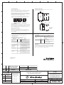
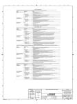
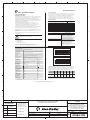
1
2
3
4
5
6
7
8
A
Installation Manual
For More Information
DeviceNet™ Push Button Stations
(Catalog Number 800F–)
Important User Information
The illustrations, charts, sample programs and layout examples shown in
this guide are intended solely for purposes of example. Since there are
many variables and requirements associated with any particular
installation, Allen-Bradley does not assume responsibility or liability (to
include intellectual property liability) for actual use based upon the
examples shown in this publication.
B
Allen-Bradley publication SGI-1.1, Safety Guidelines for the
Application, Installation, and Maintenance of Solid-State Control
(available from your local Allen-Bradley office), describes some
important differences between solid-state equipment and
electromechanical devices that should be taken into consideration when
applying products such as those described in this publication.
Reproduction of the contents of this copyrighted publication, in whole or
in part, without written permission of Allen-Bradley Company, Inc., is
prohibited.
Throughout this manual we use notes to make you aware of safety
considerations:
ATTENTION: Identifies information about practices or
circumstances that can lead to personal injury or death,
property damage or economic loss.
!
C
Related Publications
Publication Title
Publication Number
800F DeviceNet Push Button Station User Manual
800-UM002A-EN-P
800F Push Button Selection Guide
800F-SG001A-US-P
DeviceNet Cable System Planning and Installation Manual
DN-6.7.2
1756-DNB Scanner Module Configuration
1756-6.5.19
RSNetWorx for DeviceNet
1787-6.5.3
DeviceNet Media
1485-CG001A-EN-P
Cable Connection Systems – for I/O connectors
889-CG001A-US-P
DeviceLogix User Manual
ACIG-UM001A-EN-P
How To Get More Information
For
Obtain Information By
Publications in electronic format
replace the US or EN in the publication
number (800E-UM002A-FR-P).
French – FR German – DE Italian – IT
Spanish – ES Portuguese – PT Chinese – ZH
Japanese – JA Dutch – NL
Identifies information that is critical for successful
application and understanding of the product.
DeviceNet
Specifications
DeviceNet Voltage
DeviceNet Current
@ 24VDC *
External Input
Specifications
Sensor Source
Current/Voltage
External
Inputs per Station
On-State Current
External Output
Specifications
Output Auxiliary
Voltage
On-state Voltage
Drop
On-state current *
Off-state leakage
External E-Stop
Specifications
Voltage
Switching current
per contact block
½ cycle sine wave for 11milliseconds at 15G
0 to 95%
UL, CSA, and CE compliant for all applicable directives. CE
directives include EN61000-6-2, EN61000-6-4
This product is intended for use in an industrial environment.
Max
Min
25V DC – Class II Power Supply Required
930mA max load (1 sensor @ 50mA, 2
outputs @300mA)
11V DC
150mA no load
operation
Max
Min
DeviceNet Voltage (V)
Shock
Relative Humidity
Certifications
Total External Load (mA)
800F DeviceNet Push Button Stations
General Specifications
Degree of Protection
IP66, NEMA Type 4/4X/13
(Operator Dependant)
Operating Ambient
-25°C to 55°C (-13°F to +131° F) Operating temperatures below
Temperature
0°C are based on the absence of freezing moisture and liquids.
Storage Ambient
-40°C to 70°C (-40°F to 158°F)
Temperature
Vibration
10 – 2000Hz, 1.52mm displacement (peak to peak) max./2.5G max.
E
• Visiting the Automation Bookstore at –
http://www.theautomationbookstore.com
• To determine the availability of translated
publication, add a 2–letter suffix to the end
of the publication number (DN-6.7.2DE) or
Manuals in other languages
Specifications
D
• Visiting the Allen–Bradley internet site –
http://www.ab.com/manuals/
• Publication is on RSNetWorx CD–ROM
• Calling your local Allen–Bradley distributor
• Visiting the Automation Bookstore at –
http://www.theautomationbookstore.com
Publications in printed format
Attention statements help you to:
• identify a hazard
• avoid the hazard
• recognize the consequences
Important:
As part of our effort to preserve, protect, and improve our environment,
Allen–Bradley is reducing the amount of paper we use. Less paper means
more options for you. In addition to traditional printed publications and
CD–ROM versions, we now offer on–line manuals with the most
up–to–date information you can get. We recommend that you read the
related publications listed below before starting up your control system.
Maximum External Load vs. Temperature
for Minimum DeviceNet Voltage
600
500
400
300
200
100
0
-25 -20 -15 -10 -5
0
5
10 15 20 25 30 35 40 45 50 55
Temperature (C)
Minimum DeviceNet Voltage vs. Temperature
for Maximum External Load
18
17
16
15
14
13
12
11
10
-25 -20 -15 -10 -5
0
5
10 15 20 25 30 35 40 45 50 55
Temperature (C)
– / 23V
50mA / 26.5V
4: Dry contact or sinking/sourcing devices
0
13mA nominal
Max
Min
26.5V
23.5V
0.5V
–
300mA per output, 500mA per station (total)
0.05mA
Max
250V
3A
–
–
Min
–
–
Default I/O Bytes – Following are the out-of-box settings for the I/O word
format. The default I/O connection size is 2 Input Bytes and 1 Output Byte.
The size and meaning of the data can be changed by the user. For more
information, please refer to the User Manual – 800-UM002A-EN-P.
I/O
Input
Byte 0
Bit 7
Bit 6
Bit 5
Bit 4
Bit 3
Bit 2
Bit 1
Bit 0
Input 7 Input 6 Input 5 Input 4 Input 3 Input 2 Input 1 Input 0
Input
Byte 1
N/A
N/A
N/A
Out 3
Short
Circuit
Output
Byte 0
N/A
N/A
N/A
N/A
Out 2 Power
Short Supply
Circuit Fault
SSV2
Short
Circuit
SSV1
Short
Circuit
Out 3
Out 1
Out 0
Out 2
* Please refer to the following thermal derating curves for external outputs at low
DeviceNet voltages
DeviceNet is a trademark of the Open DeviceNet Vendor Association (ODVA).
DeviceLogix is a trademark of Rockwell Automation.
F
G
REFERENCE
REVISION
AUTHORIZATION
1
H
1007825
DEVICENET™ PUSH BUTTON STATION
BUL. 800F INSTRUCTION SHEET
DIMENSIONS APPLY BEFORE
SURFACE TREATMENT
(DIMENSIONS IN INCHES)
TOLERANCES UNLESS
OTHERWISE SPECIFIED
.XX:
±
N/A
.XXX:
±
N/A
ANGLES:
±
N/A
E-DOC
THIS DRAWING IS THE PROPERTY OF
THE ALLEN-BRADLEY CO. INC.
AND MAY NOT BE COPIED, USED OR
DISCLOSED FOR ANY PURPOSE EXCEPT
AS AUTHORIZED IN WRITING BY
THE ALLEN-BRADLEY CO. INC.
LOCATION :
DR.
G. Ushakow
DATE
5-18-04
DWG.
SIZE
CHKD.
M. Jutz
DATE
5-18-04
APPD.
B. Simon
DATE
5-18-04
B
MILWAUKEE,
SHEET
1
WISCONSIN
OF
U.S.A.
2
41063-195
1
2
3
4
5
6
7
8
A
Set the Node Address
Mounting the Enclosure
Valid node addresses are 00 to 63.
Dimensions in inches (millimeters). Dimensions are not intended to be
used for manufacturing purposes.
Set the node address using the rotary switches, RSNetWorx for DeviceNet
software, or another software configuration tool. Setting the switches
between 64 and 99 allows the software to have address control.
Each station is shipped with the node address set to 99. The switches are
located inside the enclosure on the circuit board. There are three switches
on the board. The Node Address switches are labeled as S1 MSB (most
significant byte) and S2 LSB (least significant byte).
4 HOLE
8.3
3 HOLE (210mm)
5.9
2 HOLE (150mm)
4.7
(120mm)
To reset the node address, use a small blade screwdriver to rotate the
switches. Line up the small black triangle with the number setting you
wish to use. Then reset the unit via power or reset service.
B
2.4
(60mm)
S1 (MSB) S2 (LSB)
S3
NODE ADDRESS BAUD RATE
Sealed
Mounting Hole
10-32 (5mm)
Screws
Set the Baud Rate
This module is equipped with Autobaud detect. Autobaud lets the station
read the network data rate and automatically synchronize to it. If the user
wishes to hard set this data rate, the third rotary switch, S3, may be used.
For more information on the baud rate switch, please refer to the user
manual - 800-UM002A-EN-P.
C
Heads of screws must
be smaller than
3/8 inch to fit inside
mounting holes.
Network and I/O Connections
This station uses 4 and 5 pin micro (12mm) style quick disconnect
connectors. The appropriate pinouts are shown on the product labeling.
If there are further questions, please refer to the user manual 800-UM002A-EN-P.
The following table describes the logic status indicator.
Troubleshoot with the Indicators
The 800F Push Button Station has the following indicators:
• Mod/Net status indicator
• Logic status indicator
The following table describes the mod/net status indicator.
D
Logic Status LED
Logic State
LED
DeviceLogix is NOT
Enabled
Off
Note: Logic could be present on the device.
This LED only reflects whether or not it
is enabled.
Combined Module/Network Status LED
Mod/Net State
Not Powered/Not
On-Line
Device Operational AND
On-Line, Connected
LED
Off
Indication
Device is not on-line.
• The device has not completed the
Dup MAC ID test yet.
• The device may not be powered yet.
Solid Green
The device is operating in a normal
condition and the device is on-line with
connections in the established state.
• For a Group 2 Only device it means
that the device is allocated to a master.
Device Operational AND
On-Line, Not Connected
Or
Flashing
Device On-Line AND
Green
Device needs
comissioning
E
Minor Fault and/or
Connection Time-Out
Critical Fault or Critical
Link Failure
F
DeviceLogix is Enabled Solid Green
Logic is enabled.
DeviceLogix is Enabled
and Forces Enabled
Forces are enabled.
Flashing
Green
Note: This implies that logic is also
enabled because outputs don't get forced
unless logic is enabled
DeviceLogix
The device is on-line with no connections
in the established state.
• The device has passed the Dup MAC
•
Indication
Logic is disabled.
This station is equipped with DeviceLogix, which allows it to run simple
and fast local logic. For more information on DeviceLogix configuration,
please refer to the 800F Push Button Station User Manual - 800-UM002A-EN-P
and the DeviceLogix User Manual - ACIG-UM001A-EN-P.
ID test, is on-line, but has no established
connections to other nodes.
For a Group 2 Only device it means
that the device is not allocated to a master.
Recoverable fault and/or one or more I/O
connections are in the Timed-out state.
Flashing Red Recoverable faults include:
• Failed Power Supply power-up test.
• Faulted 24VDC, Out2, Out3.
Solid Red
The device has an unrecoverable fault;
may need replacing.
The device has detected an error that
has rendered it incapable of communication
on the network (Dup MAC failure or bus-off).
41063-195-01 (1)
Printed in U.S.A.
-01
G
PART
NO.
1
TWO SIDED PRINTED,
BODY STOCK WHITE,
BODY INK BLACK
CHG.
LTR.
8-1/2" W x 11" H
FLAT
MATERIAL
4-1/4" W x 2-3/4" H
FOLDED
FINISHED SIZE
REFERENCE
REVISION
AUTHORIZATION
1
H
1007825
DEVICENET™ PUSH BUTTON STATION
BUL. 800F INSTRUCTION SHEET
DIMENSIONS APPLY BEFORE
SURFACE TREATMENT
(DIMENSIONS IN INCHES)
TOLERANCES UNLESS
OTHERWISE SPECIFIED
.XX:
±
N/A
.XXX:
±
N/A
ANGLES:
±
N/A
E-DOC
THIS DRAWING IS THE PROPERTY OF
THE ALLEN-BRADLEY CO. INC.
AND MAY NOT BE COPIED, USED OR
DISCLOSED FOR ANY PURPOSE EXCEPT
AS AUTHORIZED IN WRITING BY
THE ALLEN-BRADLEY CO. INC.
LOCATION :
DR.
G. Ushakow
DATE
5-18-04
DWG.
SIZE
CHKD.
M. Jutz
DATE
5-18-04
APPD.
B. Simon
DATE
5-18-04
B
MILWAUKEE,
SHEET
2
WISCONSIN
OF
U.S.A.
2
41063-195