1
Push
DeviceNet
Button Stations
with
DeviceLogix
Component
Technology
Bulletin 800E
User Manual
File Name: AB_PBStations_800E_bulletin_D201
Important User Information
Because of the variety of uses for the products described in this publication, those responsible
for the application and use of this control equipment must satisfy themselves that all
necessary steps have been taken to assure that each application and use meets all performance
and safety requirements, including any applicable laws, regulations, codes and standards.
The illustrations, charts, sample programs and layout examples shown in this guide are
intended solely for purposes of example. Since there are many variables and requirements
associated with any particular installation, Allen-Bradley does not assume responsibility or
liability (to include intellectual property liability) for actual use based upon the examples
shown in this publication.
Allen-Bradley Publication SGI-1.1, Safety Guidelines for the Application, Installation and
Maintenance of Solid-State Control (available from your local Allen-Bradley office), describes
some important differences between solid-state equipment and electromechanical devices
that should be taken into consideration when applying products such as those described in
this publication.
Reproduction of the contents of this copyrighted publication, in whole or part, without
written permission of Rockwell Automation, is prohibited.
Throughout this manual we use notes to make you aware of safety considerations:
ATTENTION
Identifies information about practices or circumstances that can lead
to personal injury or death, property damage or economic loss
!
Attention statements help you to:
• identify a hazard
• avoid a hazard
• recognize the consequences
IMPORTANT
Identifies information that is critical for successful application and
understanding of the product.
Allen-Bradley, RSNetWorx, DeviceLogix, PLC, and SLC are registered trademarks of Rockwell Automation
DeviceNet is a trademark of the Open DeviceNet Vendor Association (ODVA).
European Communities (EC) Directive Compliance
This product has the CE mark and is approved for installation within the European Union
and EEA regions. It has been designed and tested to meet the following directives.
EMC Directive
This product is tested to meet the Council Directive 89/336/EC Electromagnetic
Compatibility (EMC) by applying the following standards, in whole or in part, documented in
a technical construction file:
• EN 50081-2 EMC — Generic Emission Standard, Part 2 — Industrial Environment
• EN 50082-2 EMC — Generic Immunity Standard, Part 2 — Industrial Environment
This product is intended for use in an industrial environment.
Low Voltage Directive
This product is not required to meet Council Directive 73/23/EEC Low Voltage, as it is
designed for use with a voltage rating below 50V for alternating current and below 75V for
direct current. The requirements of EN 60947-5-1:1997 Low-Voltage Switchgear and
Controlgear, Part 5 — Control Circuit Devices, have been applied.
Table of Contents
Preface
Intended Audience . . . . . . . . . . . . . . . . . . . . . . . . . . . . . . . . . . . . . . . . . . . . . . . . . . . . . . . . . . P-i
Vocabulary . . . . . . . . . . . . . . . . . . . . . . . . . . . . . . . . . . . . . . . . . . . . . . . . . . . . . . . . . . . . . . . P-ii
Related Publications . . . . . . . . . . . . . . . . . . . . . . . . . . . . . . . . . . . . . . . . . . . . . . . . . . . . . . . . P-ii
Online Information . . . . . . . . . . . . . . . . . . . . . . . . . . . . . . . . . . . . . . . . . . . . . . . . . . . . . . . . P-ii
Chapter 1 — Overview of DeviceNet Push Button Stations
Chapter Objectives . . . . . . . . . . . . . . . . . . . . . . . . . . . . . . . . . . . . . . . . . . . . . . . . . . . . . . . . . . 1-1
Description . . . . . . . . . . . . . . . . . . . . . . . . . . . . . . . . . . . . . . . . . . . . . . . . . . . . . . . . . . . . . . . . 1-1
Summary of Features . . . . . . . . . . . . . . . . . . . . . . . . . . . . . . . . . . . . . . . . . . . . . . . . . . . . 1-2
Station Features . . . . . . . . . . . . . . . . . . . . . . . . . . . . . . . . . . . . . . . . . . . . . . . . . . . . . . . . . . . . 1-3
Operator Positions . . . . . . . . . . . . . . . . . . . . . . . . . . . . . . . . . . . . . . . . . . . . . . . . . . . . . . . . . . 1-3
Rotary Switches . . . . . . . . . . . . . . . . . . . . . . . . . . . . . . . . . . . . . . . . . . . . . . . . . . . . . . . . . . . . 1-4
DeviceNet Connection. . . . . . . . . . . . . . . . . . . . . . . . . . . . . . . . . . . . . . . . . . . . . . . . . . . . . . . 1-5
I/O Connectors . . . . . . . . . . . . . . . . . . . . . . . . . . . . . . . . . . . . . . . . . . . . . . . . . . . . . . . . . . . . 1-6
E-Stop Connectors. . . . . . . . . . . . . . . . . . . . . . . . . . . . . . . . . . . . . . . . . . . . . . . . . . . . . . . . . . 1-7
Auxiliary Components . . . . . . . . . . . . . . . . . . . . . . . . . . . . . . . . . . . . . . . . . . . . . . . . . . . . . . . 1-7
Replacement Parts . . . . . . . . . . . . . . . . . . . . . . . . . . . . . . . . . . . . . . . . . . . . . . . . . . . . . . . . . . 1-7
Chapter 2 — Quick Start
Chapter Objectives . . . . . . . . . . . . . . . . . . . . . . . . . . . . . . . . . . . . . . . . . . . . . . . . . . . . . . . . . . 2-1
Data Rate Configuration . . . . . . . . . . . . . . . . . . . . . . . . . . . . . . . . . . . . . . . . . . . . . . . . . . . . . 2-1
Node Address Configuration. . . . . . . . . . . . . . . . . . . . . . . . . . . . . . . . . . . . . . . . . . . . . . . . . . 2-1
Bulletin 800E Station Parameter Configuration . . . . . . . . . . . . . . . . . . . . . . . . . . . . . . . . . . . 2-2
Scanner Configuration . . . . . . . . . . . . . . . . . . . . . . . . . . . . . . . . . . . . . . . . . . . . . . . . . . . . . . . 2-5
Chapter 3 — Installation and Mounting
Chapter Objectives . . . . . . . . . . . . . . . . . . . . . . . . . . . . . . . . . . . . . . . . . . . . . . . . . . . . . . . . . . 3-1
DeviceNet Guidelines . . . . . . . . . . . . . . . . . . . . . . . . . . . . . . . . . . . . . . . . . . . . . . . . . . . . . . . 3-1
Equipment Needed . . . . . . . . . . . . . . . . . . . . . . . . . . . . . . . . . . . . . . . . . . . . . . . . . . . . . . . . . 3-1
Removing the Enclosure Cover. . . . . . . . . . . . . . . . . . . . . . . . . . . . . . . . . . . . . . . . . . . . . . . . 3-2
Setting the Rotary Switches . . . . . . . . . . . . . . . . . . . . . . . . . . . . . . . . . . . . . . . . . . . . . . . . . . . 3-3
Setting the Data Rate . . . . . . . . . . . . . . . . . . . . . . . . . . . . . . . . . . . . . . . . . . . . . . . . . . . . 3-3
Setting the DeviceNet Node Address. . . . . . . . . . . . . . . . . . . . . . . . . . . . . . . . . . . . . . . 3-5
Bulletin 800E Station Approximate Dimensions . . . . . . . . . . . . . . . . . . . . . . . . . . . . . . . . . . 3-6
Mounting the Bulletin 800E Station . . . . . . . . . . . . . . . . . . . . . . . . . . . . . . . . . . . . . . . . . . . . 3-7
ii
Table of Contents
Chapter 4 — Operations
Chapter Objectives . . . . . . . . . . . . . . . . . . . . . . . . . . . . . . . . . . . . . . . . . . . . . . . . . . . . . . . . . 4-1
Parameter Configuration . . . . . . . . . . . . . . . . . . . . . . . . . . . . . . . . . . . . . . . . . . . . . . . . . . . . . 4-1
Parameter 1 — Hardware Input States . . . . . . . . . . . . . . . . . . . . . . . . . . . . . . . . . . . . . 4-3
Parameter 2 — Hardware Output States . . . . . . . . . . . . . . . . . . . . . . . . . . . . . . . . . . . . 4-3
Parameter 3 — I/O Fault Status . . . . . . . . . . . . . . . . . . . . . . . . . . . . . . . . . . . . . . . . . . 4-4
Parameter 4 — Network Inputs. . . . . . . . . . . . . . . . . . . . . . . . . . . . . . . . . . . . . . . . . . . 4-4
Parameter 5 — Network Outputs . . . . . . . . . . . . . . . . . . . . . . . . . . . . . . . . . . . . . . . . . 4-5
Parameter 6 — Module Status . . . . . . . . . . . . . . . . . . . . . . . . . . . . . . . . . . . . . . . . . . . . 4-5
Parameter 7 — Function Block Outputs 1…16 . . . . . . . . . . . . . . . . . . . . . . . . . . . . . . 4-6
Parameter 8 — Function Block Outputs 17…32 . . . . . . . . . . . . . . . . . . . . . . . . . . . . . 4-7
Parameter 9 — Function Block Outputs 33…42 . . . . . . . . . . . . . . . . . . . . . . . . . . . . . 4-8
Parameter 10 — Hardware Input and I/O Fault Status . . . . . . . . . . . . . . . . . . . . . . . . 4-9
Parameter 11 — Autobaud Enable . . . . . . . . . . . . . . . . . . . . . . . . . . . . . . . . . . . . . . . . 4-9
Parameter 12 — Off-to-On Delay. . . . . . . . . . . . . . . . . . . . . . . . . . . . . . . . . . . . . . . . 4-10
Parameter 13 — On-to-Off Delay. . . . . . . . . . . . . . . . . . . . . . . . . . . . . . . . . . . . . . . . 4-10
Parameter 14 — Output Assembly . . . . . . . . . . . . . . . . . . . . . . . . . . . . . . . . . . . . . . . 4-11
Parameter 15 — Input Assembly. . . . . . . . . . . . . . . . . . . . . . . . . . . . . . . . . . . . . . . . . 4-12
Parameters 16…19 — Input Assembly Words. . . . . . . . . . . . . . . . . . . . . . . . . . . . . . 4-14
Parameter 20 — Input COS Mask . . . . . . . . . . . . . . . . . . . . . . . . . . . . . . . . . . . . . . . . 4-15
Parameter 21 — Module Status COS Mask . . . . . . . . . . . . . . . . . . . . . . . . . . . . . . . . 4-16
Parameter 22 — Function Block 1…16 COS Mask . . . . . . . . . . . . . . . . . . . . . . . . . . 4-17
Parameter 23 — Function Block 17…32 COS Mask . . . . . . . . . . . . . . . . . . . . . . . . . 4-18
Parameter 24 — Function Block 33…42 COS Mask . . . . . . . . . . . . . . . . . . . . . . . . . 4-19
Parameter 25 — Set to Defaults. . . . . . . . . . . . . . . . . . . . . . . . . . . . . . . . . . . . . . . . . . 4-20
Parameter 26 — Network Override. . . . . . . . . . . . . . . . . . . . . . . . . . . . . . . . . . . . . . . 4-20
Parameter 27 — Communication Override . . . . . . . . . . . . . . . . . . . . . . . . . . . . . . . . 4-20
Parameter 28 — MAC ID Switch Changed . . . . . . . . . . . . . . . . . . . . . . . . . . . . . . . . 4-21
Parameter 29 — Baud Rate Switch Changed . . . . . . . . . . . . . . . . . . . . . . . . . . . . . . . 4-21
Parameter 30 — MAC ID Switch Value . . . . . . . . . . . . . . . . . . . . . . . . . . . . . . . . . . . 4-21
Parameter 31 — Baud Rate Switch Value . . . . . . . . . . . . . . . . . . . . . . . . . . . . . . . . . . 4-21
Parameters 32, 39, 46, and 53 — Output Value . . . . . . . . . . . . . . . . . . . . . . . . . . . . . 4-22
Parameters 33, 40, 47, and 54 — Output Status . . . . . . . . . . . . . . . . . . . . . . . . . . . . . 4-22
Parameters 34, 41, 48, and 55 — Output Fault State . . . . . . . . . . . . . . . . . . . . . . . . . 4-22
Parameters 35, 42, 49, and 56 — Output Fault Value . . . . . . . . . . . . . . . . . . . . . . . . 4-23
Parameters 36, 43, 50, and 57 — Output Idle State . . . . . . . . . . . . . . . . . . . . . . . . . . 4-23
Parameters 37, 44, 51, and 58 — Output Idle Value . . . . . . . . . . . . . . . . . . . . . . . . . 4-23
Parameters 38, 45, 52, and 59 — Output Flash Rate . . . . . . . . . . . . . . . . . . . . . . . . . 4-24
Parameter 60 — DeviceNet Voltage . . . . . . . . . . . . . . . . . . . . . . . . . . . . . . . . . . . . . . 4-24
Parameter 61 — I/O Bus Voltage . . . . . . . . . . . . . . . . . . . . . . . . . . . . . . . . . . . . . . . . 4-24
I/O Configuration. . . . . . . . . . . . . . . . . . . . . . . . . . . . . . . . . . . . . . . . . . . . . . . . . . . . . . . . . 4-25
Publication 800E-UM002A-EN-P February 2001
Table of Contents
iii
Chapter 5 — Troubleshooting and Maintenance
Chapter Objectives . . . . . . . . . . . . . . . . . . . . . . . . . . . . . . . . . . . . . . . . . . . . . . . . . . . . . . . . . . 5-1
Preventive Maintenance . . . . . . . . . . . . . . . . . . . . . . . . . . . . . . . . . . . . . . . . . . . . . . . . . . . . . . 5-1
Using the Mod/Net Status LED . . . . . . . . . . . . . . . . . . . . . . . . . . . . . . . . . . . . . . . . . . . . . . . 5-2
Using the Logic Status LED . . . . . . . . . . . . . . . . . . . . . . . . . . . . . . . . . . . . . . . . . . . . . . . . . . 5-2
Replacing a Pilot Lamp . . . . . . . . . . . . . . . . . . . . . . . . . . . . . . . . . . . . . . . . . . . . . . . . . . . . . . 5-3
Chapter 6 — DeviceLogix
Chapter Objectives . . . . . . . . . . . . . . . . . . . . . . . . . . . . . . . . . . . . . . . . . . . . . . . . . . . . . . . . . . 6-1
Overview. . . . . . . . . . . . . . . . . . . . . . . . . . . . . . . . . . . . . . . . . . . . . . . . . . . . . . . . . . . . . . . . . . 6-1
Enabling DeviceLogix . . . . . . . . . . . . . . . . . . . . . . . . . . . . . . . . . . . . . . . . . . . . . . . . . . . . . . . 6-2
Logic Editor . . . . . . . . . . . . . . . . . . . . . . . . . . . . . . . . . . . . . . . . . . . . . . . . . . . . . . . . . . . . . . . 6-3
Sample Configuration. . . . . . . . . . . . . . . . . . . . . . . . . . . . . . . . . . . . . . . . . . . . . . . . . . . . . . . . 6-7
Forcing . . . . . . . . . . . . . . . . . . . . . . . . . . . . . . . . . . . . . . . . . . . . . . . . . . . . . . . . . . . . . . . . . . 6-10
Chapter 7 — Off-Line Node Recovery
Chapter Objectives . . . . . . . . . . . . . . . . . . . . . . . . . . . . . . . . . . . . . . . . . . . . . . . . . . . . . . . . . . 7-1
Overview. . . . . . . . . . . . . . . . . . . . . . . . . . . . . . . . . . . . . . . . . . . . . . . . . . . . . . . . . . . . . . . . . . 7-1
Sample Recovery . . . . . . . . . . . . . . . . . . . . . . . . . . . . . . . . . . . . . . . . . . . . . . . . . . . . . . . . . . . 7-2
Appendix A — Specifications
Appendix B — Cat. No. Explanation
Publication 800E-UM002A-EN-P February 2001
iv
Table of Contents
Appendix C — DeviceNet Information
General Information . . . . . . . . . . . . . . . . . . . . . . . . . . . . . . . . . . . . . . . . . . . . . . . . . . . . . . . . C-1
Message Types . . . . . . . . . . . . . . . . . . . . . . . . . . . . . . . . . . . . . . . . . . . . . . . . . . . . . . . . . . . . . C-1
Class Services . . . . . . . . . . . . . . . . . . . . . . . . . . . . . . . . . . . . . . . . . . . . . . . . . . . . . . . . . . . . . . C-1
Object Classes . . . . . . . . . . . . . . . . . . . . . . . . . . . . . . . . . . . . . . . . . . . . . . . . . . . . . . . . . . . . . C-2
Class Code 0x0001: Identity Object. . . . . . . . . . . . . . . . . . . . . . . . . . . . . . . . . . . . . . . . C-3
Class Code 0x0002: Message Router Object . . . . . . . . . . . . . . . . . . . . . . . . . . . . . . . . . C-3
Class Code 0x0003: DeviceNet Object . . . . . . . . . . . . . . . . . . . . . . . . . . . . . . . . . . . . . C-4
Class Code 0x0004: Assembly Object . . . . . . . . . . . . . . . . . . . . . . . . . . . . . . . . . . . . . . C-5
Class Code 0x0005: Connection Object . . . . . . . . . . . . . . . . . . . . . . . . . . . . . . . . . . . C-12
Class Code 0x0008: Discrete Input Point Object . . . . . . . . . . . . . . . . . . . . . . . . . . . . C-17
Class Code 0x0009: Discrete Output Point Object. . . . . . . . . . . . . . . . . . . . . . . . . . . C-18
Class Code 0x001D: Discrete Input Group Object . . . . . . . . . . . . . . . . . . . . . . . . . . C-19
Class Code 0x001E: Discrete Output Group Object . . . . . . . . . . . . . . . . . . . . . . . . . C-19
Class Code 0x002B: Acknowledge Handler Object . . . . . . . . . . . . . . . . . . . . . . . . . . C-20
Class Code 0x00B4: DeviceNet Interface Object . . . . . . . . . . . . . . . . . . . . . . . . . . . . C-21
Class Code 0x0307: Boolean Function Block Object . . . . . . . . . . . . . . . . . . . . . . . . . C-22
Class Code 0x0308: Bistable Function Block Object . . . . . . . . . . . . . . . . . . . . . . . . . C-24
Class Code 0x0309: Counter Function Block Object . . . . . . . . . . . . . . . . . . . . . . . . . C-25
Class Code 0x030A: Timer Function Block Object . . . . . . . . . . . . . . . . . . . . . . . . . . C-26
Class Code 0x030E: Logic Supervisor Object . . . . . . . . . . . . . . . . . . . . . . . . . . . . . . . C-28
Class Code 0x030F: Produced Network Data Object . . . . . . . . . . . . . . . . . . . . . . . . C-29
Publication 800E-UM002A-EN-P February 2001
Preface
The purpose of this manual is to provide you with the necessary information to apply the
Bulletin 800E DeviceNet Push Button Station with DeviceLogix Component Technology.
Described in this manual are methods for installing, configuring, and troubleshooting the
Bulletin 800E DeviceNet Push Button Station.
ATTENTION
Read this manual in its entirety before installing, operating, servicing,
or configuring the Bulletin 800E DeviceNet Push Button Station.
!
Intended Audience
This manual is intended for qualified personnel responsible for the setup and service of these
devices. You must have previous experience with and a basic understanding of
communications terminology, configuration procedures, required equipment, and safety
precautions.
You should understand the DeviceNet network operations, including how slave devices
operate on the network and communicate with a DeviceNet master.
You should be familiar with the use of the RSNetWorx for DeviceNet Software
(Cat. No. 9357-DNETL3) for network configuration. This software package is referred to
often in this manual.
ATTENTION
!
• Read the DeviceNet Cable System Planning and Installation
Manual, Publication 1485-6.7.1, in its entirety before planning
and installing a DeviceNet System. If the network is not installed
according to this document, unexpected operation and
intermittent failures can occur.
If this manual is not available, consult your local Allen-Bradley
Authorized Distributor or Sales Office to request a copy. Copies
may also be ordered from the Rockwell Automation Bookstore,
The bookstore can be contacted via the Internet from the
Allen-Bradley home page at http://www.ab.com.
• Only personnel familiar with DeviceNet devices and associated
equipment should plan or implement the installation, startup,
configuration, and subsequent maintenance of the Bulletin 800E
DeviceNet Push Button Station with DeviceLogix Component
Technology. Failure to comply may result in personal injury and/
or equipment damage.
Publication 800E-UM002A-EN-P February 2001
P-ii
Preface
Vocabulary
In this manual we refer to the:
Bulletin 800E DeviceNet Push Button Station with DeviceLogix Component
Technology as “Bulletin 800E Station”.
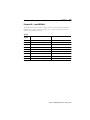
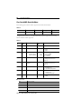
Related Publications
Table P.A
Publication Title
Publication Number
Bulletin 800E 22 mm Push Button Selection Guide
800E-SG001A-US-P
DeviceNet Cable System Planning and Installation Manual
DN-6.7.2
ControlLogix DeviceNet Interface Module User Manual
1756-6.5.19
DeviceNet Manager Software User Manual
1787-6.5.3
DeviceNet Media Catalog Guide
1485-CG001A-EN-P
Cable Connection Systems — for I/O connectors Catalog Guide
889-CG001A-US-P
DeviceLogix User Manual
ACIG-UM001A-EN-P
Online Information
EDS Files — EDS files are available for downloading at
http://www.ab.com/networks/eds
Manuals Online — Manuals are available for order or download at
http://www.theautomationbookstore.com
This manual gives an overview of the Bulletin 800E Station and describes how to configure,
install, operate, and troubleshoot the device on the DeviceNet network.
Publication 800E-UM002A-EN-P February 2001
Chapter
1
Overview of DeviceNet Push Button Stations
Chapter Objectives
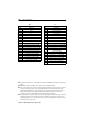
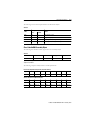
This chapter provides an overview of the Bulletin 800E Station and its features. It contains
the following information:
Table 1.A
Section
Page
Section
Page
Description
1-1
I/O Connectors
1-6
Station Features
1-3
E-Stop Connectors
1-7
Operator Positions
1-3
Auxiliary Components
1-7
Rotary Switches
1-4
Replacement Parts
1-7
DeviceNet Connection
1-5
—
—
Description
The Bulletin 800E Station offers DeviceNet connection for applications in which network
communication is desired. All of the functionality of the DeviceNet interface is contained
within the enclosure. The entire unit is powered from the DeviceNet network — a separate
power supply is not required. However, if you are powering external I/O from the unit,
adequate power supply requirements should be considered.
The Bulletin 800E Station is available as a fully configured two-, three- or four-hole station,
and can be mounted horizontally or vertically. Up to two external I/O and E-stop connectors
are available, depending upon the number and style of Bulletin 800E operators.
This is an eight-input/four-output device. Two inputs and one output are assigned to each
hole position; a two-hole device uses four inputs and two outputs and a four-hole device uses
all eight inputs and four outputs internally. Up to four unassigned I/O points can be used for
external connections. Therefore, the two-hole enclosure can have up to four I/O points
available through two external I/O connectors. The three-hole enclosure can have up to two
I/O points available through one external I/O connector. The four-hole enclosure does not
allow an external I/O connection.
Publication 800E-UM002A-EN-P February 2001
1-2
Overview of DeviceNet Push Button Stations
E-stop connectors are available for a hardwired connection to the E-stop string in all
enclosure sizes. The use of an E-stop connector requires the use of an E-stop button in the
last position and will use one of the available I/O connector positions. As mentioned above,
only two external connectors are available for I/O and E-stops.
This station also contains two new features in the DeviceNet architecture: Off-Line Node
Recovery and DeviceLogix Component Technology. Off-Line Node Recovery allows a device
to be recovered when a Duplicate Node Address situation occurs on the system (refer to
Chapter 7). The revolutionary new DeviceLogix Component Technology allows local logic
control (refer to Chapter 6).
Summary of Features
•
•
•
•
•
•
•
•
•
•
•
•
•
•
•
•
•
•
•
Uses robust Bulletin 800EP operators with three-across back-of-panel components
Many operator and I/O choices means great flexibility
Fully pre-wired at the factory
Available in two-, three-, and four-hole versions
Up to four external I/O points available through quick-disconnect connectors
Hardwired E-stop connectors available
DeviceLogix Component Technology
NEMA 4/13, IP66 environmental rating
Available as horizontal or vertical configuration
Powered by DeviceNet connection
Optional legend frame holders to customize your station
Illuminated operators use super-bright, long-life LEDs
Reliable low voltage contact blocks used for all operators
External Outputs and Sensor Source Voltage (SSV) are short-circuit protected
Mod/Net and Logic Status LEDs are visible on the outside of the enclosure
Off-Line Node Recovery
Auto Device Replacement
Baud rate can be set through rotary switches or through the use of Autobaud
Node address can be set through rotary switches or through software node
commissioning
• DeviceNet and Power Supply voltage measurement attributes
• Customized I/O assemblies
Publication 800E-UM002A-EN-P February 2001
Overview of DeviceNet Push Button Stations
1-3
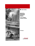
Station Features
Figure 1.1
Data Rate Rotary Switch
Node Address Rotary Switches
800E Operator
800E Legend Frame
External I/O or
E-Stop Connector
Logic Status LED
Mod/Net Status LED
External I/O Connector
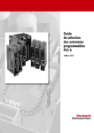
Operator Positions
The operator position starts with 0 and increases as you move away from the DeviceNet
connector. The figures below give examples of both horizontal and vertical stations.
Figure 1.2 Horizontal Station
DeviceNet Connector is
always on the right for
horizontal stations.
Pos. 3
Pos. 2
Pos. 1
Pos. 0
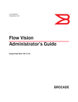
Figure 1.3 Vertical Station
DeviceNet Connector is always
on top for vertical stations.
Pos. 0
Pos. 1
Publication 800E-UM002A-EN-P February 2001
1-4
Overview of DeviceNet Push Button Stations
Figure 1.4 Connector Positions
Connector A
Connector B
Rotary Switches
The Bulletin 800E Station has three 10-position rotary switches for setting:
• DeviceNet Baud Rate
• DeviceNet Node Address
The switches are located inside the enclosure on the circuit board. The switch settings and
functions are shown below.
Figure 1.5 Rotary Switches
MSB ➊
LSB ➊
Node Address
➊ MSB = Most Significant Byte
LSB = Least Significant Byte
Publication 800E-UM002A-EN-P February 2001
Baud Rate
Overview of DeviceNet Push Button Stations
1-5
DeviceNet Connection
The Bulletin 800E Station receives all power and communications through the DeviceNet
Cable. A separate power supply is not required. The station connects to the DeviceNet
network through a standard micro connector.
Table 1.B DeviceNet Micro Connector
Micro Connector
1 DRAIN
4 WHITE
5 BLUE
2 RED
Pin #
Signal
Function
Color
1
SHIELD
SHIELD
Uninsulated
2
V DC+
Power Supply
Red
3
COM
Common
Black
4
CAN_H
Signal High
White
5
CAN_L
Signal Low
Blue
3 BLACK
Publication 800E-UM002A-EN-P February 2001
1-6
Overview of DeviceNet Push Button Stations
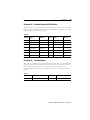
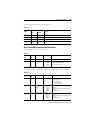
I/O Connectors
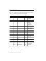
There are 22 combinations of I/O and E-stop options available to the customer, but there are
only five I/O connector variations. The pinouts are shown below.
Table 1.C Micro Connector
I/O
1 in/
1 out
Output
Configuration
Connector Type
Sinking
1
2
5
4
1 in/
1 out
3
Sourcing
1
2
5
4
2 in
3
—
1
2
5
4
2 out
3
Sinking
1
2
5
4
2 out
3
Sourcing
1
2
5
4
Publication 800E-UM002A-EN-P February 2001
3
Pinout
Pin
Signal Name
1
Sensor Source Voltage
2
Output A
3
Return
4
Input A
5
24V DC
1
Sensor Source Voltage
2
Output A
3
Return
4
Input A
5
Not Used
1
Sensor Source Voltage
2
Input B
3
Return
4
Input A
5
Not Used
1
24V DC
2
Output B
3
Not Used
4
Output A
5
Not Used
1
Not Used
2
Output B
3
Return
4
Output A
5
Not Used
Overview of DeviceNet Push Button Stations
1-7
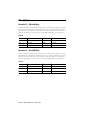
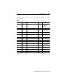
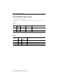
E-Stop Connectors
There are 22 combinations of I/O and E-stop options available to the customer, but there are
only two E-stop connector variations. The option of two E-stop contact blocks is for
customers that have multiple E-stop strings or the need to switch more than 3 A of current.
The pinouts are shown below.
The nomenclature NC in Signal Name stands for Normally Closed. On the “one E-stop
contact block” version, pins 1 and 4 are tied together, and 2 and 3 are tied together at
terminals C1 and C2 on the contact block, respectively. On the “two E-stop contact block”
version, NC1 represents the first contact block, NC2 represents the second contact block,
and no pins are tied together.
Table 1.D
Micro Connector
E-Stop
Output Configuration
1 E-stop
contact block
—
Connector Type
1
4
2 E-stop
contact blocks
Pinout
2
Pin
Signal Name
1
NC - C1
2
NC - C2
3
NC - C2
4
NC - C1
3
—
1
2
4
3
1
NC1- C1
2
NC1- C2
3
NC2 - C1
4
NC2 - C2
Auxiliary Components
DeviceNet components and I/O cables are available from Rockwell Automation sold
separately. It is your responsibility to install and implement the DeviceNet network according
to DeviceNet guidelines.
Replacement Parts
The Bulletin 800E Stations are pre-assembled with all of the parts required to install and use
the product. The installer needs only to supply the mounting hardware.
Replacement parts for Bulletin 800E components (operators, contact blocks, and lamps) are
sold separately. Refer to the 22 mm Push Button Selection Guide
(Publication 800E-SG001A-US-P) or the Industrial Controls Catalog (Publication A113) for
more information.
Publication 800E-UM002A-EN-P February 2001
Chapter
2
Quick Start
Chapter Objectives
This chapter provides the necessary steps to get the DeviceNet station operating on the
network. It contains the following information:
•
•
•
•
Data Rate Configuration
Node Address Configuration
Bulletin 800E Parameter Configuration
Scanner Configuration
Data Rate Configuration
Rotary switch 3 (S3) sets the data rate at which the Bulletin 800E Station communicates on
the network. The factory default setting is 9 — Autobaud.
Figure 2.1
MSB
LSB
Node Address
Baud Rate
For more information on data rate configuration, refer to Chapter 3 — Installation and
Mounting (Setting the Data Rate).
Node Address Configuration
Rotary switches 1 (S1) and 2 (S2) can be used to set the node address (0…63) of the push
button station on the network. The factory default is 99 on the switches. This causes the unit
to default to software configuration and a node address of 63.
Publication 800E-UM002A-EN-P February 2001
Quick Start
2-2
Figure 2.2
MSB
LSB
Node Address
Baud Rate
For more information on node address configuration, refer to Chapter 3 — Installation and
Mounting (Setting the DeviceNet Node Address).
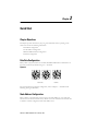
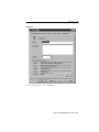
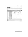
Bulletin 800E Station Parameter Configuration
For proper operation, the parameters of the push button station must be configured. There
are 61 total parameters in the push button station, but 20 of them are read-only (for
monitoring purposes). The parameters can be configured by using RSNetWorx for
DeviceNet.
Figure 2.3
Publication 800E-UM002A-EN-P February 2001
2-3
Quick Start
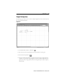
To access the parameter configuration screen from the on-line view, double-click the
Bulletin 800E Station icon.
Figure 2.4
Select the Device Parameters tab.
Publication 800E-UM002A-EN-P February 2001
Quick Start
2-4
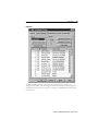
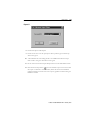
Figure 2.5
The Bulletin 800E Station will work without any parameter changes, but for logic
configuration, parameters must be changed. For more information on device configuration
and parameter selection, refer to Chapter 4 — Operations, and RSNetWorx for DeviceNet
documentation.
Publication 800E-UM002A-EN-P February 2001
2-5
Quick Start
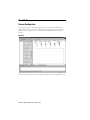
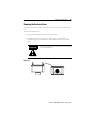
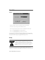
Scanner Configuration
For proper operation in a networked application, the scanner must be configured. The
Bulletin 800E Station can also run in stand-alone mode using DeviceLogix. The following
graphics show the configuration of a 1756-DNB from the RSNetWorx for DeviceNet
software.
Figure 2.6
To access the scanner module from an on-line view, double-click the 1756-DNB scanner icon.
Publication 800E-UM002A-EN-P February 2001
Quick Start
2-6
Figure 2.7
To access the Scanlist Editor, select the Scanlist tab.
Publication 800E-UM002A-EN-P February 2001
2-7
Quick Start
Figure 2.8
Add the Bulletin 800E Station to the Scanlist. Select the device in the Available Devices list. To
have the software automatically assign I/O addresses, select the “Automap on Add” selection
box. Click the > button.
Publication 800E-UM002A-EN-P February 2001
Quick Start
2-8
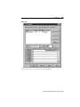
Figure 2.9
To download changes to the scanner, select the Download to Scanner button. To view/edit I/O
parameters, click the Edit I/O Parameters button.
Note that the default option is a Change of State message with the message size being
two input bytes and one output byte. The message size of this device is not fixed; the message
size and content can be changed. Refer to Chapter 4 — Operations (I/O Configuration).
Publication 800E-UM002A-EN-P February 2001
2-9
Quick Start
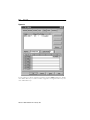
Figure 2.10
To view/edit the mapping of the input data, click the Cancel or OK button to return to the
Scanner Module screen. Select the Input tab.
Publication 800E-UM002A-EN-P February 2001
Quick Start
2-10
Figure 2.11
To view/edit the mapping of the output data, select the Output tab.
Publication 800E-UM002A-EN-P February 2001
2-11
Quick Start
Figure 2.12
To view/edit the auto device replacement parameters, click the ADR tab. Select the “Enable
Auto-Address Recovery” box. Click Load Device Config. Select “Configuration Recovery” and
“Auto Address Recovery”.
Publication 800E-UM002A-EN-P February 2001
Quick Start
2-12
Figure 2.13
For more information on scanner configuration, refer to the DeviceNet Scanner Configuration
Manual (Publication 1756-6.5.15) for the ControlLogix platform.
Publication 800E-UM002A-EN-P February 2001
Chapter
3
Installation and Mounting
Chapter Objectives
This chapter describes how to install and mount a standard Bulletin 800E Station. It contains
the following information:
Table 3.A
Section
Page
Section
Page
DeviceNet Guidelines
Equipment Needed
3-1
Setting the Rotary Switches
3-3
3-1
Bulletin 800E Station Approximate
Dimensions
3-6
Removing the Enclosure Cover
3-2
Mounting the Bulletin 800E Station
3-7
DeviceNet Guidelines
It is your responsibility to install and implement the DeviceNet network and supported
devices according to the DeviceNet guidelines.
Equipment Needed
Install the Bulletin 800E Station using standard electrician’s tools.
• Slotted or Phillips screwdrivers of standard and small sizes.
Publication 800E-UM002A-EN-P February 2001
Installation and Mounting
3-2
Removing the Enclosure Cover
To set the rotary switches, maintain, and mount the station, you must remove the enclosure
cover.
To remove the enclosure cover:
1. Using a slotted screwdriver, remove the four cover screws.
2. Carefully fold the cover to the right on a vertical station or to the bottom on a
horizontal station. Do not disconnect the ribbon cable between the cover and the
base.
ATTENTION
If removing the ribbon cable is necessary, note the orientation
for correct reinstallation.
!
Figure 3.1
Publication 800E-UM002A-EN-P February 2001
3-3
Installation and Mounting
Setting the Rotary Switches
The settings of the rotary switches on the circuit board determine:
• DeviceNet Data Rate
• DeviceNet Node Address
The location of the rotary switches is shown below.
Figure 3.2
Node Address
Data Rate
Setting the Data Rate
Rotary switch 3 (S3) sets the data rate at which the Bulletin 800E Station communicates on
the DeviceNet network. The factory default setting is 9 — Autobaud.
Figure 3.3
Data Rate
Publication 800E-UM002A-EN-P February 2001
Installation and Mounting
3-4
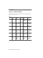
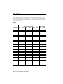
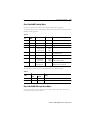
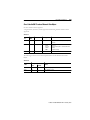
The data rate determines the maximum length of the DeviceNet Cable.
Table 3.B
Switch Position
Data Rate
Cable Length (Max.)
0
125 KB
500 m (1600 ft)
1
250 KB
200 m (600 ft)
2
500 KB
100 m (300 ft)
3…9
Autobaud
Refer to above, based on data rate of connected network
To set the DeviceNet data rate:
1. Refer to Table 3.B to select the correct data rate.
2. If automatic baud rate selection is desired, set switch 3 (S3) in Position 3…9. This
disables the switch and allows the device to synchronize to an operational network (if
Autobaud is disabled through parameter setup, this selection is not valid and the
station will set the baud rate to the last valid setting saved).
There are two parameters that monitor the physical settings of the data rate setting.
Parameter 31 reports the actual value on the switch. This is useful because there is no need to
open the enclosure to check the switch setting. Parameter 29 indicates whether the switch has
been changed since power was applied.
Publication 800E-UM002A-EN-P February 2001
3-5
Installation and Mounting
Setting the DeviceNet Node Address
Rotary switches 1 (S1) and 2 (S2) set the node address (0…63) of the Bulletin 800E station.
The factory default is 99; this invokes software configuration where the default is 63.
Figure 3.4
MSB
LSB
Node Address
To set the DeviceNet node address:
1. Set the Most Significant Byte (MSB) switch, switch 1 (S1), to the “tens” position. For
example, if the desired node address is 27, set switch 1 (S1) to 2.
2. Set the Least Significant Byte (LSB) Switch, switch 2 (S2), to the “ones” position. For
example, if the desired node address is 27, set switch 2 (S2) to 7.
3. If software programmability is desired, set the node address to 64 or greater. This
disables both switches and allows programming through the network. Software will
default to 63.
There are two parameters that monitor the physical settings of the node address settings.
Parameter 30 reports the actual value on the switches. This is useful because there is no need
to open the enclosure to check the switch settings. Parameter 28 indicates whether the
switches have been changed since power was applied.
Publication 800E-UM002A-EN-P February 2001
Installation and Mounting
3-6
Bulletin 800E Station Approximate Dimensions
The figures below show the dimensions of the Bulletin 800E Stations. Dimensions are in
inches (millimeters). Dimensions are not intended to be used for manufacturing purposes.
Figure 3.5
6.7
(170.8)
5.5
(140.0)
7.9
(200.8)
10.3
(260.8)
6.7
(170.0)
9.1
(230.0)
Publication 800E-UM002A-EN-P February 2001
3-7
Installation and Mounting
Mounting the Bulletin 800E Station
Dimensions are in inches (millimeters). Dimensions are not intended to be used for
manufacturing purposes.
Figure 3.6
8.3
(210)
5.9
(150)
4.7
(120)
2.4
(60)
2.4
(60)
2.4
(60)
➊
➊ 10-32 (5 mm) screws: Heads of screws must be smaller than 3/8" (9.5 mm) to fit inside mounting holes.
Publication 800E-UM002A-EN-P February 2001
Chapter
4
Operations
Chapter Objectives
Table 4.A
Section
Page
Section
Page
Parameter Configuration
4-1
I/O Configuration
4-25
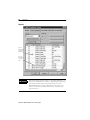
Parameter Configuration
There are 61 parameters available for monitoring in the Bulletin 800E Station, 41 of which
can be changed. Configuration of the parameters is accomplished through the use of
RSNetWorx for DeviceNet. The following illustration helps explain which parameters are
configurable and which are for monitoring.
Publication 800E-UM002A-EN-P February 2001
4-2
Operations
Figure 4.1
The lock
indicates this
is a read-only
parameter.
The scale
indicates this
is a scaled
value.
IMPORTANT
When downloading parameter changes to the Bulletin 800E Station, it is
important to download one at a time (i.e., single selected). When trying
to download all, there will be an object state conflict error if the
Bulletin 800E Station is running a DeviceLogix configuration or if a
master is in control of the station. Parameters 14…19, and 25 will
generate this error.
Publication 800E-UM002A-EN-P February 2001
Operations
4-3
The following tables give a brief explanation of the individual parameters and their uses.
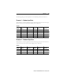
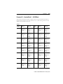
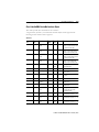
Parameter 1 — Hardware Input States
This parameter is a read-only parameter used for monitoring. It shows the value on the eight
inputs of the device. For external input mapping, refer to Table 4.AL.
Table 4.B
Bit
Number
Function
When = 1
Function
When = 0
Bit
Number
Function
When = 1
Function
When = 0
8…15
—
—
3
Input 3 Active
Input 3 Inactive
7
Input 7 Active
Input 7 Inactive
2
Input 2 Active
Input 2 Inactive
6
Input 6 Active
Input 6 Inactive
1
Input 1 Active
Input 1 Inactive
5
Input 5 Active
Input 5 Inactive
0
Input 0 Active
Input 0 Inactive
4
Input 4 Active
Input 4 Inactive
—
—
—
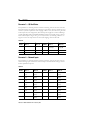
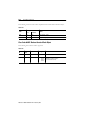
Parameter 2 — Hardware Output States
This parameter is a read-only parameter used for monitoring. It shows the value on the four
outputs of the device. For external output mapping, refer to Table 4.AL.
Table 4.C
Bit
Number
Function
When = 1
Function
When = 0
Bit
Number
Function
When = 1
Function
When = 0
4…15
—
—
1
Output 1 Active
Output 1 Inactive
3
Output 3 Active
Output 3 Inactive
0
Output 0 Active
Output 0 Inactive
2
Output 2 Active
Output 2 Inactive
—
—
—
Publication 800E-UM002A-EN-P February 2001
4-4
Operations
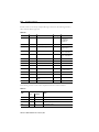
Parameter 3 — I/O Fault Status
This parameter is a read-only parameter used for monitoring. It shows the value on the five
fault status bits that are related to the external I/O of the device. There is one SSV per I/O
connector (a further explanation of the mapping of SSV to the I/O connectors is given later
in this chapter in I/O Configuration). The internal power supply bit is used for indicating a
possible impending failure. The Bulletin 800E Station keeps the internal voltage at 25V no
matter what the input voltage is. If it goes too low, this bit is set, indicating a failure or too
large of a load on an output. For short circuit I/O mapping, refer to Table 4.AL.
Table 4.D
Bit
Number
Function
When = 1
Function
When = 0
Bit
Number
Function
When = 1
Function
When = 0
5…15
—
—
2
Internal Power Supply
Out of Range
Internal Power
Supply OK
4
Output 3 Short Circuit
Output 3 OK
1
SSVB Short Circuit
SSVB OK
3
Output 2 Short Circuit
Output 2 OK
0
SSVA Short Circuit
SSVA OK
Parameter 4 — Network Inputs
This parameter is a read-only parameter used for monitoring. It shows the value on the 16
network message inputs of the device. Network Inputs are used with DeviceLogix and are
further explained in Chapter 6.
Table 4.E
Bit
Number
Function
When = 1
Function
When = 0
Bit
Number
Function
When = 1
Function
When = 0
15
Net Input 15
Active
Net Input 15
Inactive
7
Net Input 7 Active
Net Input 7
Inactive
14
Net Input 14
Active
Net Input 14
Inactive
6
Net Input 6 Active
Net Input 6
Inactive
13
Net Input 13
Active
Net Input 13
Inactive
5
Net Input 5 Active
Net Input 5
Inactive
12
Net Input 12
Active
Net Input 12
Inactive
4
Net Input 4 Active
Net Input 4
Inactive
11
Net Input 11
Active
Net Input 11
Inactive
3
Net Input 3 Active
Net Input 3
Inactive
10
Net Input 10
Active
Net Input 10
Inactive
2
Net Input 2 Active
Net Input 2
Inactive
9
Net Input 9 Active
Net Input 9
Inactive
1
Net Input 1 Active
Net Input 1
Inactive
8
Net Input 8 Active
Net Input 8
Inactive
0
Net Input 0 Active
Net Input 0
Inactive
Publication 800E-UM002A-EN-P February 2001
Operations
4-5
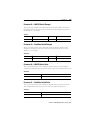
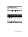
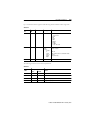
Parameter 5 — Network Outputs
This parameter is a read-only parameter used for monitoring. It shows the value on the eight
network message outputs of the device. Network Outputs are used with DeviceLogix and are
further explained in Chapter 6.
Table 4.F
Bit
Number
Function
When = 1
Function
When = 0
Bit
Number
Function
When = 1
Function
When = 0
8…15
—
—
3
Net Output 3
Active
Net Output 3
Inactive
7
Net Output 7
Active
Net Output 7
Inactive
2
Net Output 2
Active
Net Output 2
Inactive
6
Net Output 6
Active
Net Output 6
Inactive
1
Net Output 1
Active
Net Output 1
Inactive
5
Net Output 5
Active
Net Output 5
Inactive
0
Net Output 0
Active
Net Output 0
Inactive
4
Net Output 4
Active
Net Output 4
Inactive
—
—
—
Parameter 6 — Module Status
This parameter is a read-only parameter used for monitoring. It shows the value on the eleven
status bits that are related to the module status of the device.
Table 4.G
Bit
Number
Function
When = 1
Function
When = 0
Bit
Number
Function
When = 1
Function
When = 0
11…15
—
—
5
COS Message
CNXN faulted
COS Message
CNXN OK
10
Power Supply
Faulted
Power Supply OK
4
Poll Message
CNXN faulted
Poll Message
CNXN OK
9
Minor Fault exists
Minor Fault does
not exist
3
Explicit Message
CNXN faulted
Explicit Message
CNXN OK
8
Network Fault
exists
Network fault
does not exist
2
COS Message
CNXN exists
COS Message
CNXN does not
exist
7
COS Message
CNXN idle
COS Message
CNXN not idle
1
Poll Message
CNXN exists
Poll Message
CNXN does not
exist
6
Poll Message
CNXN idle
Poll Message
CNXN not idle
0
Explicit Message
CNXN exists
Explicit Message
CNXN does not
exist
Publication 800E-UM002A-EN-P February 2001
4-6
Operations
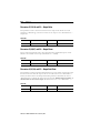
Parameter 7 — Function Block Outputs 1…16
This parameter is a read-only parameter used for monitoring. It shows the value on the
output of the first 16 function blocks from the logic editor. Function blocks are used with
DeviceLogix and are further explained in Chapter 6.
ATTENTION
The function block numbers may change as a DeviceLogix
configuration is updated.
!
Table 4.H
Bit
Number
Function
When = 1
Function
When = 0
Bit
Number
Function
When = 1
Function
When = 0
15
Function Block 16
Output Active
Function Block 16
Output Inactive
7
Function Block 8
Output Active
Function Block 8
Output Inactive
14
Function Block 15
Output Active
Function Block 15
Output Inactive
6
Function Block 7
Output Active
Function Block 7
Output Inactive
13
Function Block 14
Output Active
Function Block 14
Output Inactive
5
Function Block 6
Output Active
Function Block 6
Output Inactive
12
Function Block 13
Output Active
Function Block 13
Output Inactive
4
Function Block 5
Output Active
Function Block 5
Output Inactive
11
Function Block 12
Output Active
Function Block 12
Output Inactive
3
Function Block 4
Output Active
Function Block 4
Output Inactive
10
Function Block 11
Output Active
Function Block 11
Output Inactive
2
Function Block 3
Output Active
Function Block 3
Output Inactive
9
Function Block 10
Output Active
Function Block 10
Output Inactive
1
Function Block 2
Output Active
Function Block 2
Output Inactive
8
Function Block 9
Output Active
Function Block 9
Output Inactive
0
Function Block 1
Output Active
Function Block 1
Output Inactive
Publication 800E-UM002A-EN-P February 2001
Operations
4-7
Parameter 8 — Function Block Outputs 17…32
This parameter is a read-only parameter used for monitoring. It shows the value on the
output of the second 16 function blocks from the logic editor. Function blocks are used with
DeviceLogix and are further explained in Chapter 6.
ATTENTION
The function block numbers may change as a DeviceLogix
configuration is updated.
!
Table 4.I
Bit
Number
Function
When = 1
Function
When = 0
Bit
Number
Function
When = 1
Function
When = 0
15
Function Block 32
Output Active
Function Block 32
Output Inactive
7
Function Block 24
Output Active
Function Block 24
Output Inactive
14
Function Block 31
Output Active
Function Block 31
Output Inactive
6
Function Block 23
Output Active
Function Block 23
Output Inactive
13
Function Block 30
Output Active
Function Block 30
Output Inactive
5
Function Block 22
Output Active
Function Block 22
Output Inactive
12
Function Block 29
Output Active
Function Block 29
Output Inactive
4
Function Block 21
Output Active
Function Block 21
Output Inactive
11
Function Block 28
Output Active
Function Block 28
Output Inactive
3
Function Block 20
Output Active
Function Block 20
Output Inactive
10
Function Block 27
Output Active
Function Block 27
Output Inactive
2
Function Block 19
Output Active
Function Block 19
Output Inactive
9
Function Block 26
Output Active
Function Block 26
Output Inactive
1
Function Block 18
Output Active
Function Block 18
Output Inactive
8
Function Block 25
Output Active
Function Block 25
Output Inactive
0
Function Block 17
Output Active
Function Block 17
Output Inactive
Publication 800E-UM002A-EN-P February 2001
4-8
Operations
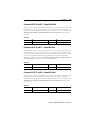
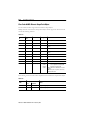
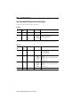
Parameter 9 — Function Block Outputs 33…42
This parameter is a read-only parameter used for monitoring. It shows the value on the
output of the final 10 function blocks from the logic editor. Function blocks are used with
DeviceLogix and are further explained in Chapter 6.
ATTENTION
The function block numbers may change as a DeviceLogix
configuration is updated.
!
Table 4.J
Bit
Number
Function
When = 1
Function
When = 0
Bit
Number
Function
When = 1
Function
When = 0
10…15
—
—
4
Function Block 37
Output Active
Function Block 37
Output Inactive
9
Function Block 42
Output Active
Function Block 42
Output Inactive
3
Function Block 36
Output Active
Function Block 36
Output Inactive
8
Function Block 41
Output Active
Function Block 41
Output Inactive
2
Function Block 35
Output Active
Function Block 35
Output Inactive
7
Function Block 40
Output Active
Function Block 40
Output Inactive
1
Function Block 34
Output Active
Function Block 34
Output Inactive
6
Function Block 39
Output Active
Function Block 39
Output Inactive
0
Function Block 33
Output Active
Function Block 33
Output Inactive
5
Function Block 38
Output Active
Function Block 38
Output Inactive
—
—
—
Publication 800E-UM002A-EN-P February 2001
Operations
4-9
Parameter 10 — Hardware Input and I/O Fault Status
This parameter is a read-only parameter used for monitoring. It shows the value on the eight
inputs of the device and the I/O Fault Status. This is combination of Parameters 1 and 3. For
further description, refer to these parameters.
Table 4.K
Bit
Number
Function
When = 1
Function
When = 0
Bit
Number
Function
When = 1
Function
When = 0
13…15
—
—
6
Input 6 Active
Input 6 Inactive
12
Output 3 Short Circuit
Output 3 OK
5
Input 5 Active
Input 5 Inactive
11
Output 2 Short Circuit
Output 2 OK
4
Input 4 Active
Input 4 Inactive
10
Internal Power Supply
Out of Range
Internal Power
Supply OK
3
Input 3 Active
Input 3 Inactive
9
SSVB Short Circuit
SSVB OK
2
Input 2 Active
Input 2 Inactive
8
SSVA Short Circuit
SSVA OK
1
Input 1 Active
Input 1 Inactive
7
Input 7 Active
Input 7 Inactive
0
Input 0 Active
Input 0 Inactive
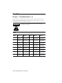
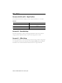
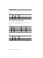
Parameter 11 — Autobaud Enable
When enabled, the push button station automatically communicates at the network baud rate
detected at power-on. When disabled, the baud rate must be set correctly by the user during
node commissioning. This parameter’s setting takes effect after a module reset or at
power-on. Note: Only valid when rotary switch is set between 3…9. The default value is
Enabled.
Table 4.L
Value
Function
Value
Function
0
Disabled
1
Enabled
Publication 800E-UM002A-EN-P February 2001
4-10
Operations
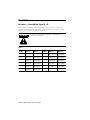
Parameter 12 — Off-to-On Delay
The Off-to-On delay determines the amount of time for which an input signal must be fully
present before the push button station updates the I/O. It is a means of filtering for noise on
input lines. The value must be set in units of microseconds. The default is set to 8000 µs to
ensure proper filtering on noisy lines, but it can be reduced depending on the application.
Table 4.M
Value (µ
µs)
Function
Value (µ
µs)
Function
0
0 ms delay
8000
8 ms delay
2000
2 ms delay
16000
16 ms delay
4000
4 ms delay
—
—
Parameter 13 — On-to-Off Delay
The On-to-Off delay determines the amount of time for which an input signal must be fully
absent before the push button station updates the I/O. It is a means of filtering for noise on
input lines. The value must be set in units of microseconds. The default is set to 8000 µs to
ensure proper filtering on noisy lines, but it can be reduced depending on the application.
Table 4.N
Value (µ
µs)
Function
Value (µ
µs)
Function
0
0 ms delay
8000
8 ms delay
2000
2 ms delay
16000
16 ms delay
4000
4 ms delay
—
—
Publication 800E-UM002A-EN-P February 2001
Operations
4-11
Parameter 14 — Output Assembly
The output assembly consumes data from the network (e.g., the output image table from the
master). This parameter controls where the data is stored.
• If the data is meant for physical outputs, use Assembly 33.
• If the data is meant for Network Inputs, use Assembly 183. (This is the same as
Parameter 4. Refer to Parameter 4 for bit explanation.)
DeviceLogix uses Network Inputs. For more information on DeviceLogix, refer to
Chapter 6. If a DeviceLogix configuration is used in the device, the Bulletin 800E Station will
automatically map Assembly 33 to Network Inputs and the physical outputs will only be
controlled by DeviceLogix. The ramification of this is that only four Network Inputs are then
allowed instead of the 16 allowed if Assembly 183 is mapped.
This parameter cannot be changed while the I/O is active, meaning that all DeviceLogix
configurations must be disabled and the Master must be put in program mode. No I/O
connections can exist, because the meaning of the data will change. Furthermore, the size of
the I/O connection must change if this parameter is changed (This affects the scanner
configuration). Assembly 33 can only consume one byte of data, Assembly 183 consumes
two bytes of data. The default for this parameter is 33.
Table 4.O
Value — Assembly Number
Function
33
Hardware Outputs — 1 byte of data
183
Network Inputs (Parameter 4) — 2 bytes of data
Publication 800E-UM002A-EN-P February 2001
4-12
Operations
Parameter 15 — Input Assembly
The input assembly produces data to the network (e.g., to the input image table of the
master). This parameter controls where the data comes from.
• If the data is meant to reflect the status of the eight physical inputs, use Assembly 4.
• If the data is meant to reflect the status of the eight physical inputs and the I/O Fault
Status, use Assembly 101. (This is the same data as Parameter 10. Refer to
Parameter 10 for bit explanation.)
• If the data is meant to reflect the status of the DeviceLogix Network Outputs, use
Assembly 184. (This is the same data as Parameter 5. Refer to Parameter 5 for bit
explanation.)
• If the data is meant to reflect the DeviceLogix Hardware Inputs, use Assembly 180.
(This is the same data as Parameter 1. Refer to Parameter 1 for bit explanation.)
• If the data is meant to reflect the Hardware Output Status, use Assembly 181. (This is
the same data as Parameter 2. Refer to Parameter 2 for bit explanation.)
• If the data is meant to reflect the I/O Fault Status only, use Assembly 182. (This is the
same data as Parameter 3. Refer to Parameter 3 for bit explanation.)
• If the data is meant to reflect the DeviceLogix Function Block 1…16 Outputs, use
Assembly 186. (This is the same data as Parameter 7. Refer to Parameter 7 for bit
explanation.) Note: Function Block numbering will change as the DeviceLogix
program is changed.
• If the data is meant to reflect the DeviceLogix Function Block 17…32 Outputs, use
Assembly 187. (This is the same data as Parameter 8. Refer to Parameter 8 for bit
explanation.) Note: Function Block numbering will change as the DeviceLogix
program is changed.
• If the data is meant to reflect the DeviceLogix Function Block 33…42 Outputs, use
Assembly 188. (This is the same data as Parameter 9. Refer to Parameter 9 for bit
explanation.) Note: Function Block numbering will change as the DeviceLogix
program is changed.
• If the data is meant to reflect the Module Status Outputs, use Assembly 185. (This is
the same data as Parameter 6. Refer to Parameter 6 for bit explanation.)
• If the customer desires flexibility in the Input configuration, use Assembly 100. This
parameter is then used with Parameters 16…19 and configurable up to 8 bytes of
data.
Publication 800E-UM002A-EN-P February 2001
Operations
4-13
This parameter cannot be changed while the I/O is active, meaning that all DeviceLogix
configurations must be disabled and the Master must be put in program mode. No I/O
connections can exist, because the meaning of the data will change. Furthermore, the size of
the I/O connection must change if this parameter is changed (this affects the scanner
configuration). Assembly 101 is the default.
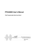
Table 4.P
Value — Assembly Number
Function (Same as Parameter x) — Number of Bytes of Data
4
Hardware Inputs — 1 byte
100
Customizable use with Parameters 16…19 — Up to 8 bytes
101
Hardware Inputs and Diagnostic Data (Parameter 10) — 2 bytes
180
Hardware Inputs (Parameter 1) — 2 bytes
181
Hardware Output Status (Parameter 2) — 2 bytes
182
I/O Fault Status (Parameter 3) — 2 bytes
184
Network Outputs (Parameter 5) — 2 bytes
185
Module Status (Parameter 6) — 2 bytes
186
DeviceLogix Function Block 1…16 Outputs (Parameter 7) — 2 bytes
187
DeviceLogix Function Block 17…32 Outputs (Parameter 8) — 2 bytes
188
DeviceLogix Function Block 33…42 Outputs (Parameter 9) — 2 bytes
Publication 800E-UM002A-EN-P February 2001
4-14
Operations
Parameters 16…19 — Input Assembly Words
These parameters are used in conjunction with Parameter 15. When Parameter 15 is set to
Assembly 100, then these parameters become active. The user can select which data will get
sent back in the input data. The assembly word chosen will match an existing parameter (refer
to Table 4.Q), for bit explanations refer to corresponding parameter. Each parameter is
equivalent to two bytes of data.
These parameters cannot be changed while the I/O is active, meaning that all DeviceLogix
configurations must be disabled and the Master must be put in program mode. No I/O
connections can exist, because the meaning of the data will change. Furthermore, the size of
the I/O connection must change if this parameter is changed. If 0 is chosen, all Input
Assembly Words after this one are ignored. For instance, if Parameter 16 is set to 1,
Parameter 17 to 3, and Parameter 18 to 0, then Parameters 18 and 19 are ignored. This means
that four bytes (two words) of data are being returned to the master, and the I/O connection
size in the scanner should be set appropriately. The defaults are 1, 3, 5, and 6, respectively.
Table 4.Q
Value — Assembly Number
Function (Data From)
0
Produce no data from this position and all subsequent positions
1
Hardware Inputs (Parameter 1)
2
Hardware Output Status (Parameter 2)
3
I/O Fault Status (Parameter 3)
4
Network Inputs (Parameter 4)
5
Network Outputs (Parameter 5)
6
Module Status (Parameter 6)
7
DeviceLogix Function Block 1…16 Outputs (Parameter 7)
8
DeviceLogix Function Block 17…32 Outputs (Parameter 8)
9
DeviceLogix Function Block 33…42 Outputs (Parameter 9)
10
Hardware Inputs and Diagnostic Data (Parameter 10)
Publication 800E-UM002A-EN-P February 2001
Operations
4-15
Parameter 20 — Input COS Mask
This parameter determines whether a Change of State message should be initiated when a
hardware input changes state. If the mask for a bit = 1, then a message will be sent. The
default for this parameter is all ones.
Table 4.R
Bit
Number
If Mask = 1
If Mask = 0
8…15
—
—
7
Input 7 Change initiates a message
Input 7 Change does not initiate a message
6
Input 6 Change initiates a message
Input 6 Change does not initiate a message
5
Input 5 Change initiates a message
Input 5 Change does not initiate a message
4
Input 4 Change initiates a message
Input 4 Change does not initiate a message
3
Input 3 Change initiates a message
Input 3 Change does not initiate a message
2
Input 2 Change initiates a message
Input 2 Change does not initiate a message
1
Input 1 Change initiates a message
Input 1 Change does not initiate a message
0
Input 0 Change initiates a message
Input 0 Change does not initiate a message
Publication 800E-UM002A-EN-P February 2001
4-16
Operations
Parameter 21 — Module Status COS Mask
This parameter determines whether a Change of State message should be initiated when a
module status bit changes state. If the mask for a bit = 1, then a message will be sent. The
default for this parameter is all zeroes.
Table 4.S
Bit
Number
Function
When = 1
Function
When = 0
Bit
Number
Function
When = 1
Function
When = 0
11…15
—
—
5
COS Message
CNXN faulted —
Change initiates a
message
COS Message
CNXN faulted —
Change does not
initiate a
message
10
Power Supply
fault — Change
initiates a
message
Power Supply
fault — Change
does not initiate a
message
4
Poll Message
CNXN faulted —
Change initiates a
message
Poll Message
CNXN faulted —
Change does not
initiate a
message
9
Minor Fault —
Change initiates a
message
Minor Fault —
Change does not
initiate a
message
3
Explicit Message
CNXN faulted —
Change initiates a
message
Explicit Message
CNXN faulted —
Change does not
initiate a
message
8
Network Fault —
Change initiates a
message
Network fault —
Change does not
initiate a
message
2
COS Message
CNXN exists —
Change initiates a
message
COS Message
CNXN exists —
Change does not
initiate a
message
7
COS Message
CNXN idle —
Change initiates a
message
COS Message
CNXN idle —
Change does not
initiate a
message
1
Poll Message
CNXN exists —
Change initiates a
message
Poll Message
CNXN exists —
Change does not
initiate a
message
6
Poll Message
CNXN idle —
Change initiates a
message
Poll Message
CNXN idle —
Change does not
initiate a
message
0
Explicit Message
CNXN exists —
Change initiates a
message
Explicit Message
CNXN exists —
Change does not
initiate a
message
Publication 800E-UM002A-EN-P February 2001
Operations
4-17
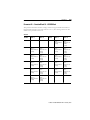
Parameter 22 — Function Block 1…16 COS Mask
This parameter determines whether a Change of State message should be initiated when a
function block bit changes state. If the mask for a bit = 1, then a message will be sent. The
default for this parameter is all zeroes.
Table 4.T
Bit
Number
Function
When = 1
Function
When = 0
Bit
Number
Function
When = 1
Function
When = 0
15
Function Block 16
Output —
Change initiates a
message
Function Block 16
Output —
Change does not
initiate a
message
7
Function Block 8
Output —
Change initiates a
message
Function Block 8
Output —
Change does not
initiate a
message
14
Function Block 15
Output —
Change initiates a
message
Function Block 15
Output —
Change does not
initiate a
message
6
Function Block 7
Output —
Change initiates a
message
Function Block 7
Output —
Change does not
initiate a
message
13
Function Block 14
Output —
Change initiates a
message
Function Block 14
Output —
Change does not
initiate a
message
5
Function Block 6
Output —
Change initiates a
message
Function Block 6
Output —
Change does not
initiate a
message
12
Function Block 13
Output —
Change initiates a
message
Function Block 13
Output —
Change does not
initiate a
message
4
Function Block 5
Output —
Change initiates a
message
Function Block 5
Output —
Change does not
initiate a
message
11
Function Block 12
Output —
Change initiates a
message
Function Block 12
Output —
Change does not
initiate a
message
3
Function Block 4
Output —
Change initiates a
message
Function Block 4
Output —
Change does not
initiate a
message
10
Function Block 11
Output —
Change initiates a
message
Function Block 11
Output —
Change does not
initiate a
message
2
Function Block 3
Output —
Change initiates a
message
Function Block 3
Output —
Change does not
initiate a
message
9
Function Block 10
Output —
Change initiates a
message
Function Block 10
Output —
Change does not
initiate a
message
1
Function Block 2
Output —
Change initiates a
message
Function Block 2
Output —
Change does not
initiate a
message
8
Function Block 9
Output —
Change initiates a
message
Function Block 9
Output —
Change does not
initiate a
message
0
Function Block 1
Output —
Change initiates a
message
Function Block 1
Output —
Change does not
initiate a
message
Publication 800E-UM002A-EN-P February 2001
4-18
Operations
Parameter 23 — Function Block 17…32 COS Mask
This parameter determines whether a Change of State message should be initiated when a
function block bit changes state. If the mask for a bit = 1, then a message will be sent. The
default for this parameter is all zeroes.
Table 4.U
Bit
Number
Function
When = 1
Function
When = 0
Bit
Number
Function
When = 1
Function
When = 0
15
Function Block 32
Output —
Change initiates a
message
Function Block 32
Output —
Change does not
initiate a
message
7
Function Block 24
Output —
Change initiates a
message
Function Block 24
Output —
Change does not
initiate a
message
14
Function Block 31
Output —
Change initiates a
message
Function Block 31
Output —
Change does not
initiate a
message
6
Function Block 23
Output —
Change initiates a
message
Function Block 23
Output —
Change does not
initiate a
message
13
Function Block 30
Output —
Change initiates a
message
Function Block 30
Output —
Change does not
initiate a
message
5
Function Block 22
Output —
Change initiates a
message
Function Block 22
Output —
Change does not
initiate a
message
12
Function Block 29
Output —
Change initiates a
message
Function Block 29
Output —
Change does not
initiate a
message
4
Function Block 21
Output —
Change initiates a
message
Function Block 21
Output —
Change does not
initiate a
message
11
Function Block 28
Output —
Change initiates a
message
Function Block 28
Output —
Change does not
initiate a
message
3
Function Block 20
Output —
Change initiates a
message
Function Block 20
Output —
Change does not
initiate a
message
10
Function Block 27
Output —
Change initiates a
message
Function Block 27
Output —
Change does not
initiate a
message
2
Function Block 19
Output —
Change initiates a
message
Function Block 19
Output —
Change does not
initiate a
message
9
Function Block 26
Output —
Change initiates a
message
Function Block 26
Output —
Change does not
initiate a
message
1
Function Block 18
Output —
Change initiates a
message
Function Block 18
Output —
Change does not
initiate a
message
8
Function Block 25
Output —
Change initiates a
message
Function Block 25
Output —
Change does not
initiate a
message
0
Function Block 17
Output —
Change initiates a
message
Function Block 17
Output —
Change does not
initiate a
message
Publication 800E-UM002A-EN-P February 2001
Operations
4-19
Parameter 24 — Function Block 33…42 COS Mask
This parameter determines whether a Change of State message should be initiated when a
function block bit changes state. If the mask for a bit = 1, then a message will be sent. The
default for this parameter is all zeroes.
Table 4.V
Bit
Number
Function
When = 1
Function
When = 0
Bit
Number
Function
When = 1
Function
When = 0
10…15
—
—
4
Function Block 37
Output —
Change initiates a
message
Function Block 37
Output —
Change does not
initiate a
message
9
Function Block 42
Output —
Change initiates a
message
Function Block 42
Output —
Change does not
initiate a
message
3
Function Block 36
Output —
Change initiates a
message
Function Block 36
Output —
Change does not
initiate a
message
8
Function Block 41
Output —
Change initiates a
message
Function Block 41
Output —
Change does not
initiate a
message
2
Function Block 35
Output —
Change initiates a
message
Function Block 35
Output —
Change does not
initiate a
message
7
Function Block 40
Output —
Change initiates a
message
Function Block 40
Output —
Change does not
initiate a
message
1
Function Block 34
Output —
Change initiates a
message
Function Block 34
Output —
Change does not
initiate a
message
6
Function Block 39
Output —
Change initiates a
message
Function Block 39
Output —
Change does not
initiate a
message
0
Function Block 33
Output —
Change initiates a
message
Function Block 33
Output —
Change does not
initiate a
message
5
Function Block 38
Output —
Change initiates a
message
Function Block 38
Output —
Change does not
initiate a
message
—
—
—
Publication 800E-UM002A-EN-P February 2001
4-20
Operations
Parameter 25 — Set to Defaults
This parameter can be used to return the Bulletin 800E Station to the “out of the box”
settings. This is the easiest way to clear an unwanted logic configuration. This device cannot
be reset with logic running or with an I/O connection to the master. The default is No
Action.
Table 4.W
Value
Function
Value
Function
0
No Action
1
Reset
Parameter 26 — Network Override
Enabling this parameter allows DeviceLogix to override normal output behavior in the case
of a network fault. Network faults include Duplicate MAC ID failure and module Bus Off
conditions. The default is 0 — Disable Network Override.
Table 4.X
Value
Function
Value
Function
0
Disable Network Override
1
Enable Network Override
Parameter 27 — Communication Override
Enabling this parameter allows DeviceLogix to override normal output behavior in the event
of a communication status change. This includes all states where the module is without an
I/O connection in the run state, which occurs if the I/O connection does not exist, has timed
out, has been deleted, or is currently idle. The default is 0 — Disable Communication
Override.
Table 4.Y
Value
Function
Value
Function
0
Disable Communication Override
1
Enable Communication Override
Publication 800E-UM002A-EN-P February 2001
Operations
4-21
Parameter 28 — MAC ID Switch Changed
This is a read-only parameter used to determine whether the Node Address switches have
been changed since the last power up. If the switches have been changed this bit will be set.
The default is 0 — No Changes.
Table 4.Z
Value
Function
Value
Function
0
No changes
1
Switches have changed
Parameter 29 — Baud Rate Switch Changed
This is a read-only parameter used to determine whether the baud rate switch has been
changed since the last power up. If the switch has been changed this bit will be set. The
default is 0 — No Changes.
Table 4.AA
Value
Function
Value
Function
0
No changes
1
Switch has changed
Parameter 30 — MAC ID Switch Value
This is a read-only parameter used to identify the physical setting on the Node Address
switches. This is helpful because the enclosure does not need to be opened. The default is 99.
Table 4.AB
Value
Function
0…99
Value of switches
Parameter 31 — Baud Rate Switch Value
This is a read-only parameter used to identify the physical setting on the baud rate switch.
This is helpful because the enclosure does not need to be opened. The default is 9.
Table 4.AC
Value
Function
0…9
Value of switch
Publication 800E-UM002A-EN-P February 2001
4-22
Operations
Parameters 32, 39, 46, and 53 — Output Value
This parameter is used to view the actual status of the output. In the absence of an I/O
connection or DeviceLogix, it can also be used to set an output to test it. The default is 0 —
Output Off.
Table 4.AD
Value
Function
Value
Function
0
Output Off
1
Output On
Parameters 33, 40, 47, and 54 — Output Status
This is a read-only parameter used to show the health status of individual outputs. A fault
indicates a short circuit on the output. The default is 0 — Healthy.
Table 4.AE
Value
Function
Value
Function
0
Healthy
1
Faulted
Parameters 34, 41, 48, and 55 — Output Fault State
This parameter is used in conjunction with Parameters 35, 42, 49, and 56, respectively. It tells
the station what to do with the output in the case of a fault state. If “Go to Fault Value” is
selected, the device refers to the Output Fault Value parameter to determine the state. If
“Hold Last State” is selected, the output stays in the last state. If DeviceLogix is running, it
will determine the state of the output. The default value is 0 — Go to Fault Value.
Table 4.AF
Value
Function
Value
Function
0
Go to Fault Value
1
Hold Last State
Publication 800E-UM002A-EN-P February 2001
Operations
4-23
Parameters 35, 42, 49, and 56 — Output Fault Value
This parameter is used in conjunction with Parameters 34, 41, 48, and 56, respectively. It tells
the station what to do with the output in the case of a fault state. If “Go to Fault Value” is
selected in the previous parameter, the device will set the output to the state selected here. If
DeviceLogix is running, it will determine the state of the output. The default value is
0 — Off.
Table 4.AG
Value
Function
Value
Function
0
Off
1
On
Parameters 36, 43, 50, and 57 — Output Idle State
This parameter is used in conjunction with Parameters 37, 44, 51, and 58, respectively. It tells
the station what to do with the output in the case of an idle state (an I/O connection exists,
but the master is in program mode or idle state). If “Go to Idle Value” is selected, the device
refers to the Output Idle Value parameter to determine the state. If “Hold Last State” is
selected, the output stays in the last state. If DeviceLogix is running, it will determine the
state of the output. The default value is 0 — Go to Idle Value.
Table 4.AH
Value
Function
Value
Function
0
Go to Idle Value
1
Hold Last State
Parameters 37, 44, 51, and 58 — Output Idle Value
This parameter is used in conjunction with Parameters 36, 43, 50, and 57, respectively. It tells
the station what to do with the output in the case of a idle state. If “Go to Idle Value” is
selected in the previous parameter, the device will set the output to the state selected here. If
DeviceLogix is running, it will determine the state of the output. The default value is
0 — Off.
Table 4.AI
Value
Function
Value
Function
0
Off
1
On
Publication 800E-UM002A-EN-P February 2001
4-24
Operations
Parameters 38, 45, 52, and 59 — Output Flash Rate
This parameter determines the flashing rate of the output. The default is 0 — No Flash.
Table 4.AJ
Value
Function
0
No Flash
1
0.6 Hz
2
2 Hz
Parameter 60 — DeviceNet Voltage
This read only parameter is used for monitoring the DeviceNet voltage at the node. The
voltage reported via Parameter 60 may vary from actual voltage by up to 1V DC.
Parameter 61 — I/O Bus Voltage
This read-only parameter is used for monitoring the I/O bus voltage. If the bus voltage drops
to less than 20V, a status bit is set and a minor fault is indicated. Note: Status bit and minor
fault indicator are not latched and will be cleared when the bus voltage exceeds 20V.
Publication 800E-UM002A-EN-P February 2001
Operations
4-25
I/O Configuration
The I/O messaging is set up by the master device through client/server connections at
power-up. This device supports both Change-of-State (COS), cyclic, and Polled I/O
messaging connections. The default I/O size is two input bytes and one output byte with a
COS connection but, as explained in the Parameter Configuration, it is variable. The content
of the data is also user selectable. Refer to Parameters 14…19 for data information and
connection size. For actual bit information, you can further refer to Parameters 1…10.
As mentioned earlier, two inputs and one output are assigned per operator. For two- and
three-hole enclosures, there are external I/O points available. The following table helps to
explain this.
Table 4.AK
Enclosure Type
Operator Position 1
Operator Position 2
Operator Position 3
Operator Position 4
2-Hole
3-Hole
4-Hole
IN0
IN0
IN0
OUT0
OUT0
OUT0
IN1
IN1
IN1
IN2
IN2
IN2
OUT1
OUT1
OUT1
IN3
IN3
IN3
IN4 ➊
IN4
IN4
OUT2 ➊
OUT2
OUT2
IN5 ➊
IN5
IN5
IN6 ➊
IN6 ➊
IN6
OUT3 ➊
OUT3 ➊
OUT3
IN7 ➊
IN7 ➊
IN7
➊ This I/O point is available for external use through connectors.
Publication 800E-UM002A-EN-P February 2001
4-26
Operations
Table 4.AL explains how the external I/O maps to the hardware inputs, hardware outputs
and I/O fault status words. Table 4.AM gives a cross-reference to the I/O connector pinout.
For connector pinout diagrams, refer to Chapter 1 — Overview of DeviceNet Push Button
Stations (I/O Connectors).
Table 4.AL
I/O Mapping
Hardware Inputs and Outputs
I/O Fault Status
External I/O
Version
Input 4
IN4
Input 5
IN5
Input 6
IN6
Input 7
IN7
Output 2
OUT2
Output 3
OUT3
SSVA
SSVB
A
—
—
INA
—
—
OUTA
SSV1
—
B
—
—
INA
—
—
OUTA
SSV1
—
C
—
—
INA
INB
—
—
SSV1
—
D
—
—
—
—
OUTA
OUTB
—
—
E
—
—
—
—
OUTA
OUTB
—
—
F
—
—
—
—
—
—
—
—
G
—
—
—
—
—
—
—
—
H
INA
INB
INC
IND
—
—
SSV1
SSV2
J
INA
INB
—
—
OUTA
OUTB
SSV1
—
K
INA
INB
—
—
OUTA
OUTB
SSV1
—
L
—
—
INA
—
—
OUTA
SSV1
—
M
—
—
INA
—
—
OUTA
SSV1
—
N
—
—
INA
—
—
OUTA
SSV1
—
P
—
—
INA
—
—
OUTA
SSV1
—
Q
—
—
INA
INB
—
—
SSV1
—
R
—
—
INA
INB
—
—
SSV1
—
T
—
—
—
—
OUTA
OUTB
—
—
U
—
—
—
—
OUTA
OUTB
—
—
V
—
—
—
—
OUTA
OUTB
—
—
W
—
—
—
—
OUTA
OUTB
—
—
X
INA
INB
INC
—
OUTA
—
SSV1
SSV2
Y
INA
INB
INC
—
OUTA
—
SSV1
SSV2
Publication 800E-UM002A-EN-P February 2001
Operations
4-27
Table 4.AM
External I/O Connector Pinout
Connector A
Connector B
External I/O
Version
Pin 1
Pin 2
Pin 3
Pin 4
Pin 5
Pin 1
Pin 2
Pin 3
Pin 4
Pin 5
A
SSV1
OUTA
RTN
INA
24V DC —
—
—
—
—
B
SSV1
OUTA
RTN
INA
—
—
—
—
—
—
C
SSV1
INB
RTN
D
24V DC OUTB
—
INA
—
—
—
—
—
—
OUTA
—
—
—
—
—
—
E
—
OUTB
RTN
OUTA
—
—
—
—
—
—
F
NC-C1
NC-C2
NC-C2
NC-C1
—
—
—
—
—
—
G
NC1-C1 NC1-C2 NC2-C1 NC2-C2 —
—
—
—
—
—
H
SSV1
INB
RTN
INA
—
SSV2
IND
RTN
INC
—
J
SSV1
INB
RTN
INA
—
24V DC OUTB
—
OUTA
—
K
SSV1
INB
RTN
INA
—
—
RTN
OUTA
—
OUTB
L
SSV1
OUTA
RTN
INA
24V DC NC-C1
NC-C2
NC-C2
NC-C1
—
M
SSV1
OUTA
RTN
INA
—
NC-C2
NC-C2
NC-C1
—
N
SSV1
OUTA
RTN
INA
24V DC NC1-C1 NC1-C2 NC2-C1 NC2-C2 —
P
SSV1
OUTA
RTN
INA
—
Q
SSV1
INB
RTN
INA
—
NC-C1
R
SSV1
INB
RTN
INA
—
NC1-C1 NC1-C2 NC2-C1 NC2-C2 —
T
24V DC OUTB
OUTA
—
NC-C1
NC-C2
NC-C2
NC-C1
—
U
—
RTN
OUTA
—
NC-C1
NC-C2
NC-C2
NC-C1
—
V
24V DC OUTB
—
OUTA
—
NC1-C1 NC1-C2 NC2-C1 NC2-C2 —
W
—
OUTB
RTN
OUTA
—
NC1-C1 NC1-C2 NC2-C1 NC2-C2 —
X
SSV1
INB
RTN
INA
—
SSV2
OUTA
RTN
INC
24V DC
Y
SSV1
INB
RTN
INA
—
SSV2
OUTA
RTN
INC
—
OUTB
NC-C1
NC1-C1 NC1-C2 NC2-C1 NC2-C2 —
NC-C2
NC-C2
NC-C1
—
Publication 800E-UM002A-EN-P February 2001
Chapter
Troubleshooting and Maintenance
Chapter Objectives
Table 5.A
Section
Page
Section
Page
Preventive Maintenance
5-1
Using the Logic Status LED
5-2
Using the Mod/Net Status LED
5-2
Replacing a Pilot Lamp
5-3
Preventive Maintenance
• Prevent accumulation of dust and dirt by:
– Keeping the enclosure and operators clean
– Keeping the cover closed
• Periodically check for loose connections
ATTENTION
To avoid shock hazard, remove incoming power before checking
connections.
!
Publication 800E-UM002A-EN-P February 2001
5
Troubleshooting and Maintenance
5-2
Using the Mod/Net Status LED
Table 5.B Mod/Net Status LED
Mod/Net State
LED
Indication
Not powered/not on-line
Off
Device is not on-line.
• Device has not completed the Dup MAC ID test.
• Device may not be powered.
Device operational and
on-line, connected
Solid green
Device is operating in a normal condition and is on-line with
connections in the established state.
• For Group 2 only, the device is allocated to a master.
Device operational and
on-line, not connected,
or
device on-line and needs
commissioning
Flashing
green
Device is on-line with no connections in the established state.
• Device has passed the Dup MAC ID test, is on-line, but has no
established connections to other nodes.
• For a Group 2 Only device, the device is not allocated to a
master.
Minor fault and/or
connection time-out
Flashing red
Recoverable fault and/or one or more I/O connections are in the
timed-out state. Recoverable faults include:
• Failed Power Supply power-up test
• Faulted 24V DC, Out2, Out3
Critical fault or critical
link failure
Solid red
• Device has an unrecoverable fault and may need replacing.
• Device has detected an error that has rendered it incapable of
communication on the network (Dup MAC failure or Bus Off).
Using the Logic Status LED
Table 5.C Logic Status LED
Logic State
LED
Indication
DeviceLogix not enabled
Off
Logic is disabled.
Note: Logic may be present on the device. This LED only reflects
whether or not it is enabled.
DeviceLogix enabled
Solid green
Logic is enabled.
DeviceLogix enabled and
forces enabled
Flashing
green
Forces are enabled.
Note: Logic is also enabled. Outputs are not forced unless logic is
enabled.
Publication 800E-UM002A-EN-P February 2001
5-3
Troubleshooting and Maintenance
Replacing a Pilot Lamp
Pilot lamps should not need to be replaced, because long life LEDs are used. However if one
needs replacement, the following steps should be followed.
ATTENTION
To avoid electrical shock or unintended operation of the equipment,
remove incoming power before servicing.
!
1. Remove lens cap from the operator.
2. Remove the lamp from the socket. If necessary, use a lamp removal tool (Cat.
No. 800E-ALR1).
ATTENTION
Do not use a screwdriver or other metal object to remove
lamp.
!
3. Carefully insert new lamp in socket.
ATTENTION
!
• Use only 24V LEDs.
• Before replacing the lens cap, be sure that the lamp is
properly seated or a short circuit may result.
4. Replace the lens cap.
5. Apply power and check for proper operation.
Publication 800E-UM002A-EN-P February 2001
Chapter
6
DeviceLogix
Chapter Objectives
Table 6.A
Section
Page
Section
Page
Overview
6-1
Sample Configuration
6-7
Enabling DeviceLogix
6-2
Forcing
6-10
Logic Editor
6-3
—
—
Overview
The Bulletin 800E Station has integrated DeviceLogix Component Technology. DeviceLogix
allows very fast, simple process control. An example application may be a push button station
that is being used to jog a slide. The use of DeviceLogix gives a local response time of
approximately 1.2 ms versus 15.5 ms using a centralized PLC that is Polling the station (for
more information, refer to the DeviceLogix White Paper, available for download at
http://www.ab.com/DeviceLogix). The external I/O can be configured to turn on/off at
the push of a button and get much more accurate response.
Also with DeviceLogix, users now have the option of executing a more complex sequence of
actions upon the detection of a fault. These actions can be used to provide a more controlled
shutdown of some portion of the control system’s process. This provides an additional level
of reliability and fault tolerance in systems.
Publication 800E-UM002A-EN-P February 2001
6-2
DeviceLogix
Enabling DeviceLogix
If a DeviceLogix configuration is enabled it will run in the following circumstances:
• When an I/O connection with a master is present
• In the case of a network fault and Parameter 26 is enabled (refer to Parameter 26)
• There is no I/O connection and Parameter 27 is enabled (refer to Parameter 27)
It is important to understand that when a DeviceLogix configuration is enabled, DeviceLogix
has control of the hardware outputs. It supersedes the commands of the master or of an
explicit message. Any mapping in the master to hardware outputs will be transferred
automatically to Network Inputs. For more information on this, refer to Chapter 4 —
Operations, Parameters 4 and 14.
DeviceLogix configurations are stored in non-volatile memory and will be retained through
power cycles. However, I/O, timer, and counter values are stored in volatile memory and are
lost on a power cycle. The exception to this is Forces, which are stored in non-volatile
memory.
Publication 800E-UM002A-EN-P February 2001
DeviceLogix
6-3
Logic Editor
To access the DeviceLogix configuration tool, execute the following steps in RSNetWorx for
DeviceNet. Note: Version 3.0 or later is needed to have the Logic Editor Installed.
Figure 6.1
From an online view in RSNetWorx, double-click the Bulletin 800E Station.
Publication 800E-UM002A-EN-P February 2001
6-4
DeviceLogix
Figure 6.2
Click the DeviceLogix tab. This is where configuration description, author and revision data
are updated.
Publication 800E-UM002A-EN-P February 2001
DeviceLogix
6-5
Figure 6.3
To start the Logic Editor, click the Start Logic Editor button. A blank editor appears.
Publication 800E-UM002A-EN-P February 2001
6-6
DeviceLogix
Figure 6.4
To create a configuration, refer to Sample Configuration.
Publication 800E-UM002A-EN-P February 2001
DeviceLogix
6-7
Sample Configuration
The following steps will show how to create a simple configuration. At the end of the process
the screen should look like this.
Figure 6.5
1. In the blank editor, click the AND button.
2. Move the cursor into the grid and click to drop the function onto the grid.
3. Click the Discrete Input button.
4. The list of Hardware Inputs dialog box appears. This list shows how many inputs are
available to be placed in the logic configuration. Since the Bulletin 800E Station has
eight inputs, there are eight options in the list starting with input 0. Select “Input 0”,
then click OK.
Publication 800E-UM002A-EN-P February 2001
6-8
DeviceLogix
Figure 6.6
5. Put the image to the left of the AND function block. To drop the input on the page,
click the desired position.
6. Click the Network Input button.
Remember from earlier explanations, this is
actually data from the Master Output Image table. For more help, refer to
Chapter 4 — Operations, Parameters 4 and 14.
7. Select “Network Input 0”. Click OK.
Publication 800E-UM002A-EN-P February 2001
DeviceLogix
6-9
Figure 6.7
8. Put Network Input 0 under Input 0.
9. Put the mouse cursor over the tip of Input 0. The tip will turn green. Click the tip
when it turns green.
10. A line will follow the cursor. Bring the line to the AND function block on Input
Node 1 until it turns green. Click when it turns green.
11. Do the same for the Network Input and Input Node 2 on the AND function block.
12. Click the Discrete Output button.
This is the hardware output of the station. Once
this output is connected to a function block, neither the master nor the EDS file
parameters directly control the status of the outputs, regardless of whether the logic is
disabled or enabled.
Publication 800E-UM002A-EN-P February 2001
6-10
DeviceLogix
Figure 6.8
13. Select “Output 0” from the List of Hardware Outputs box and click OK.
14. Place the output to the right of the AND function block.
15. Once again connect the output with a line to the AND function block output.
16. Go to the Communications menu and click Download.
17. Go to the Communications menu and click Logic Enable On.
The unit should now be running your DeviceLogix configuration, and the outputs will be
controlled by the logic once the master is in Run Mode or Parameter 27 is enabled. Note that
the Logic Status LED is solid green, signifying that DeviceLogix is active.
Forcing
ATTENTION
!
Only personnel familiar with DeviceNet devices and associated
equipment should plan or implement the installation, startup,
configuration, and subsequent maintenance of the Bulletin 800E
Station. Forcing will turn on hardware and could cause operation of
equipment and could lead to personal injury and/or equipment
damage.
Forcing can be shown using the previous example configuration. Make sure that the
configuration is downloaded and enabled. Right-click the Output function and select Force On.
Publication 800E-UM002A-EN-P February 2001
DeviceLogix
6-11
Figure 6.9
The output has now turned on and the Logic Status LED has started flashing green. To
remove the force, right-click again and select Remove Force. Inputs can also be forced to verify
correct logic operation. I/O can also be forced off. Forces are stored in non-volatile memory
and will be retained through a power cycle.
Publication 800E-UM002A-EN-P February 2001
Chapter
7
Off-Line Node Recovery
Chapter Objectives
Table 7.A
Section
Page
Section
Page
Overview
7-1
Sample Recovery
7-2
Overview
The Bulletin 800E Station is equipped with a function known as Off-Line Node Recovery.
Off-Line Node Recovery is used mainly to commission a device on a network. When a new
product is put on the network, it is at a default address of Node 63. If multiple units are
placed on a network without first using node commissioning to change the node address a
duplicate MAC ID error occurs. This means that more than one device is located at the same
node address and only one of them is allowed online. Off-Line Node Recovery now allows
you to recover the faulted devices and change the node address. This is a powerful tool
because multiple nodes can be put on the network on installation and recovered one at a time
without having to continually reset the network. The following section will walk through a
sample recovery.
Note: If the MAC ID is set through the rotary switches, Off-Line Node Recovery will not be
able to recover the faulted device because it cannot change the node address.
Publication 800E-UM002A-EN-P February 2001
Off-Line Node Recovery
7-2
Sample Recovery
This example has placed two Bulletin 800E Stations on a network at the same node
address 63.
From RSNetWorx, click the Single Pass Browse button. The following message will appear in
the message box at the bottom of the screen.
Figure 7.1
Select Faulted Address Recovery Wizard from the Tools menu.
Figure 7.2
Click the Next button.
Publication 800E-UM002A-EN-P February 2001
7-3
Off-Line Node Recovery
Figure 7.3
If there are multiple faulted devices, they will show up in the list. Devices are identified by the
DeviceNet serial number that is unique to every product. The serial number for the
Bulletin 800E Station can be located on the nameplate or inside the product. Click the Next
button.
Publication 800E-UM002A-EN-P February 2001
Off-Line Node Recovery
7-4
Figure 7.4
If there are multiple faulted units, you can verify which unit you are recovering by flashing the
Mod/Net Status LED. To do this click Flash LED. The LED will flash between red and
green. Click “00” under New Address to change the new address.
Publication 800E-UM002A-EN-P February 2001
7-5
Off-Line Node Recovery
Figure 7.5
Change the address to the new address (for example, 22) and click Recover. Recovery is now
complete.
Publication 800E-UM002A-EN-P February 2001
Off-Line Node Recovery
7-6
Figure 7.6
For more information on Off-Line Node Recovery refer to the RSNetWorx for DeviceNet User
Manual (Publication 1787-6.5.3).
Publication 800E-UM002A-EN-P February 2001
Appendix
A
Specifications
Table A.A Bulletin 800E Station Specifications
General Specifications
Degree of Protection
IP66, NEMA Type 4/13
Operating Ambient Temperature
–13…+131°F (–25…+55°C) Operating temperatures below 32°F (0°C)
are based on the absence of freezing moisture and liquids.
Storage Ambient Temperature
–40…+158°F (–40…+70°C)
Vibration
10…2000 Hz, 1.52 mm displacement (peak-to-peak) max./2.5 G max.
Shock
1/2 cycle sine wave for 11 ms at 15 G
Relative Humidity
0…95%
Certifications
UL, cUL, and CE compliant for all applicable directives. CE directives
include EN50081-2, EN50082-2. This product is intended for use in an
industrial environment.
DeviceNet Specifications
Max.
Min.
DeviceNet Voltage
(Class II Power Supply Required)
25V DC
11V DC
DeviceNet Current @ 24V DC ➊
930 mA @ max. load (1 sensor @
50 mA, 2 outputs @ 300 mA)
< 150 mA (no-load operation)
External Input Specifications
Max.
Min.
Sensor Source Voltage/Current
26.5V/50 mA
23V/0 mA
External Inputs per Station
4: Dry contact or sinking/sourcing
devices
0
On-State Current
13 mA nominal
External Output Specifications
Max.
Min.
Output Auxiliary Voltage
26.5V
23.5V
On-State Voltage Drop
0.5V
—
On-State Current (continuous)
300 mA per output, 500 mA per
station (total)
—
—
Off-State Leakage
0.05 mA
External E-Stop Specifications
Max.
Min.
Voltage
250V
—
Switching Current per Contact
Block
3A
—
➊ Refer to Figure 1.1 and Figure 1.2, thermal derating curves for external outputs at low DeviceNet voltages.
Publication 800E-UM002A-EN-P February 2001
Specifications
A-2
Figure 1.1 Minimum DeviceNet Voltage vs. Temperature for
Maximum External Load
DeviceNet Voltage (V)
18
17
16
15
14
13
12
11
10
-25 -20 -15 -10 -5
0
5
10 15 20 25 30 35 40 45 50 55
Temperature (C)
Total External Load (mA)
Figure 1.2 Maximum External Load vs. Temperature for
Minimum DeviceNet Voltage
600
500
400
300
200
100
0
-25 -20 -15 -10 -5
0
5 10 15 20 25 30 35 40 45 50 55
Temperature (C)
Note: Refer to the 22 mm Push Button Selection Guide (Publication 800E-SG001A-US-P) or the
Industrial Controls Catalog (Publication A113) for more information.
Publication 800E-UM002A-EN-P February 2001
Appendix
B
Cat. No. Explanation
Figure B.1 Vertical Station
DeviceNet Connector is always
on top for vertical stations.
Hole 1
Hole 2
Figure B.2 Horizontal Station
DeviceNet Connector is
always on the right for
horizontal stations.
Hole 4
Hole 3
Hole 2
(Hole One)
c+d
(Hole Two)
c+d
(Hole One)
c+d
Hole 1
(Hole Two)
c+d
(Hole Three)
c+d
(Hole One)
c+d
(Hole Two)
c+d
Publication 800E-UM002A-EN-P February 2001
(Hole Three)
c+d
(Hole Four)
c+d
Cat. No. Explanation
B-2
➊
%&&'(&'&)*++(,-
%&.(&'&
)*++(,-
%& &(&'&
)*++( ,-
➋
%&&'(&'&)*++(,-
%&.(&'&)*++(,-
!"#$➌
!"#$➌
%& &(&'&)*++( ,%&('/!
)*++(!/,-
%&('/!
)*++(!/,-
0
#"$()*++((,-
1
%&!"2'3'4
(&'(&)*++(/2-➍➎
%&!"2'3'
)*++(/2!-➍➎
/
%&('(&'(&#"
)*++!/(,-➍
('(51$!
)*++(1/3-➏
(
('(51$!
)*++(1/3-➏
6
%&&'(&'
&)*++(,-
3
%&/$/&'+ (&'&)*++(/,-
2
%&!"1$3'
)*++(/13-➍➎
7
%&('(&'(&#"
)*++!/(3,-
%&&'(&'&
)*++(,-
8
%&('(&'(&#"
)*++!/(,-
9
%&('/!
)*++(!/,-
:
%&('/!
)*++(!/,-
;
%&/$/&'+ (&'
&)*++!/,-
➊ Selector Switches in a vertical mount enclosure will be mounted with a horizontal orientation.
➋ Legend Frame provided is 800E-120; legend insert needs to be ordered separately.
➌ Enclosure Style/Legend options G and H from Table b can only select one operator from Table c. Valid
options are K, L, M, and T. Also refer to footnote ➍ below.
➍ Operator Types K, L, M and T from Table c may be used as Emergency Stops. To be valid as an E-Stop, the
operators must use Color/Text option 4 from Table d and it must be placed in the last hole position in the
enclosure. An E-Stop connector also must be chosen from Table e. Also see footnote ➍, page B-3.
➎ Operator Types K, L, and T from Table c only available in red — Color/Text Option 4 from Table d.
➏ Operator Types N and P from Table c must select Color/Text option X from Table d.
Publication 800E-UM002A-EN-P February 2001
B-3
Cat. No. Explanation
➌
<
8
< "&< &"&)!=-
=
< "&< &"&)!&-
"&
3
&"&)!=-
>
:
&"&)!&-
?
&
@
*
$
<!"=➍
!"='➍
"& C "&
A
"
0
"& C &"&)!=-
!) =&82.-➊
1
"& C &"&)!&-
!")3=&82.-➊
< "&< &"&)!=- C< !"=➍
)==&82.-➊
/
< "&< &"&)!&- C< !"=➍
3B')==&82.-➊
< "&< &"&)!=- C !"='➍
7")==&82.-➊
)==&82.-➊
(
< "&< &"&)!&- C
!"='➍
<) =&82.-➊
+)3=&82.-➊
0
#) =&82.-➊
1
#55)3=&82.-➊
3')&=&82.-➊
9
)1$!!-➋
6
"& C<!"=➍
3
"& C!"='➍
2
&"&)!=- C<!"=➍
7
&"&)!&- C<!"=➍
&"&)!=- C!"='➍
8
&"&)!&- C!"='➍
9
"& C< "&< &"&)!=-
:
"& C< "&< &"&)!&-
➊ Legended color cap options A…L from Table d can only be used with Operator Type options A, B, and C from
Table c.
➋ Operator Types N and P from Table c must select Color/Text option X from Table d.
➌ This is an 8-in/ 4-out device. 2-in and 1-out are assigned to each hole position in the enclosure. If a 2-hole
enclosure is selected, 4-in and 2-out are assigned internally and up to 4 unassigned I/O points can be
assigned to external connectors. This device contains up to two physical external I/O connectors. The “+”
symbol in the Description field of Table e indicates that two external connectors exist. If an E-Stop
connector is used, 2 unassigned I/O points can be assigned to the other connector.
➍ External I/O Versions F, L, M, Q, T and U receive only one contact block for the external E-Stop string. These
connectors are rated to 3 A. If more than 3 A of current is needed or if there are two E-Stop strings, use
External I/O Versions G, N, P, R, V and W. These versions receive two contact blocks. This allows for 6 A of
switching or for two E-Stop strings.
Publication 800E-UM002A-EN-P February 2001
Appendix
C
DeviceNet Information
General Information
The Bulletin 800E-xx (Multifunction I/O) device operates as a slave on the DeviceNet
network. The unit supports Explicit Messages and COS, cyclic, and Polled I/O Messages of
the predefined master/slave connection set. It does not support the Explicit Unconnected
Message Manager (UCMM).
The device supports four discrete outputs and eight discrete inputs.
Message Types
As a group 2 slave device, the Bulletin 800E-xx supports the following message types.
Table C.1 Supported Message Types
CAN Identifier
Group 2 Message Type
10xxxxxx111
Duplicate MAC ID Check Messages
10xxxxxx110
Unconnected Explicit Request Messages
10xxxxxx101
Master I/O Poll Command Message
10xxxxxx100
Master Explicit Request Message
xxxxxx = Node Address
Class Services
As a group 2 slave device, the Bulletin 800E-xx supports the following class services and
instance services.
Table C.2 Class Services
Service Code
Service Name
Service Code
Service Name
14 (0x0E)
Get_Attribute_Single
75 (0x4B)
Allocate Group 2 Identifier Set
16 (0x10)
Set_Attribute_Single
76 (0x4C)
Release Group 2 Identifier Set
Publication 800E-UM002A-EN-P February 2001
C-2
DeviceNet Information
Object Classes
Objects with common attributes are members of the same class. A particular occurrence of
an object is called an instance of that class. The class and instance identifier within a
DeviceNet connection message will identify exactly what object is being referenced. In an
effort to remain compatible with other DeviceNet devices, the DeviceNet implementation
for the Push Button Station follows standard definitions of objects. The classes listed below
will be supported by the Bulletin 800E Station.
This object is used to provide identification and general information about the module. This
object must be supported per the DeviceNet specification. There will only be one instance of
this object. Attributes such as the vendor id, serial number, or product revision will be
maintained by this object.
The following object classes will be supported.
Table 3.C
Class
Object
Class
Object
0x0001
Identity
0x002B
Acknowledge Handler
0x0002
Message Router
0x00B4
DeviceNet Interface Object
0x0003
DeviceNet
0x0307
Boolean Function Block
0x0004
Assembly
0x0308
Bistable Function Block
0x0005
Connection
0x0309
Counter Function Block
0x0008
Discrete Input Point
0x030A
Timer Function Block
0x0009
Discrete Output Point
0x030E
Logic Supervisor
0x001D
Discrete Input Group
0x030F
Produced Network Data
0x001E
Discrete Output Group
—
—
Publication 800E-UM002A-EN-P February 2001
DeviceNet Information
C-3
Class Code 0x0001: Identity Object
None of the optional class attributes of the Identity Object will be supported.
A single instance (instance 1) of the Identity Object will be supported. The following instance
attributes will be supported.
Table C.4
Attribute
ID
Access
Rule
Name
Data Type
Value
1
Get
Vendor
UINT
1
2
Get
Device Type
UINT
7
3
Get
Product Code
UINT
1106 800E-H(V)4A4A4A4A
4
Get
Revision
Major Revision
Minor Revision
Structure of:
USINT
USINT
1
1
5
Get
Status
WORD
0 = not owned
1 = owned by master
6
Get
Serial Number
UDINT
unique number for each device
7
Get
Product Name
String Length
ASCII String
Structure of:
USINT
STRING
23
“800E Pushbutton Station”
Configuration
Consistency Value
UINT
9
Get
Unique value depending on output of the
parameter checksum algorithm.
The following common services will be implemented for the Identity Object.
Table C.5
Service
Code
Implemented for:
Service
Name
Class
Instance
0x0E
No
Yes
Get_Attribute_Single
0x05
No
Yes
Reset
Class Code 0x0002: Message Router Object
No class or instance attributes will be supported. The message router object exists only to
rout explicit messages to other objects.
Publication 800E-UM002A-EN-P February 2001
C-4
DeviceNet Information
Class Code 0x0003: DeviceNet Object
The following class attributes will be supported for the DeviceNet Object:
Table C.6
Attribute ID
Access Rule
Name
Data Type
Value
1
Get
Revision
UINT
2
A single instance (instance 1) of the DeviceNet Object will be supported. The following
instance attributes will be supported.
Table C.7
Attribute
ID
Access
Rule
Name
Data
Type
Value
1
Get/Set
Node Address
USINT
0…63
2
Get/Set
Baud Rate
USINT
0 = 125 K
1 = 250 K
2 = 500 K
5
Get
Allocation Info
Allocation Choice
Master Node Addr
Structure of:
BYTE
USINT
6
Get
MAC ID Switch Changed
BOOL
0 = No Change
1 = Change since last Reset or
Power-Up
7
Get
Baud Rate Switch
Changed
BOOL
0 = No Change
1 = Change since last Reset or
Power-Up
8
Get
MAC ID Switch Value
USINT
0…99
0…63 Hardware Set
64…99 Software Configurable
9
Get
Baud Rate Switch Value
USINT
0…9
0…2 Hardware Set
3…9 Software Configurable
100
Get/Set
Autobaud Enable
BOOL
0 = Disable
1 = Enable
➊ Allocation_byte
bit 0
Explicit messaging
bit 1
Polled I/O
bit 4
COS I/O
bit 5
Cyclic I/O
bit 6
Acknowledge Suppression
Publication 800E-UM002A-EN-P February 2001
Allocation_byte ➊
0…63 = address
255 = unallocated
DeviceNet Information
C-5
The following services will be implemented for the DeviceNet Object.
Table C.8
Service
Code
Implemented for:
Service
Name
Class
Instance
0x0E
Yes
Yes
Get_Attribute_Single
0x10
No
Yes
Set_Attribute_Single
0x4B
No
Yes
Allocate_Master/Slave _Connection_Set
0x4C
No
Yes
Release_Master/Slave _Connection_Set
Class Code 0x0004: Assembly Object
The following class attributes will be supported for the Assembly Object:
Table C.9
Attribute ID
Access Rule
Name
Data Type
Value
2
Get
Max Instance
UINT
188
Output Assemblies
The following Output Assembly Instances will be implemented.
Instance 33 (Output Assembly used by 8-in/4-out devices)
Byte
Bit 7
Bit 6
Bit 5
Bit 4
Bit 3
Bit 2
Bit 1
Bit 0
0
—
—
—
—
Out3
Out2
Out1
Out0
Bit 4
Bit 3
Bit 2
Bit 1
Bit 0
Table C.10 Instance 183 (Network Inputs)
Byte
Bit 7
Bit 6
Bit 5
0
Net In 7
Net In 6
Net In 5
Net In 4
Net In 3
Net In 2
Net In 1
Net In 0
1
Net In 15
Net In 14
Net In 13
Net In 12
Net In 11
Net In 10
Net In 9
Net In 8
Publication 800E-UM002A-EN-P February 2001
C-6
DeviceNet Information
The following table indicates the I/O Assembly Data Attribute mapping for Output
Assemblies.
Table C.11
Data Component
Name
Class
Name
Number
Out1
Discrete Output Point
09hex
Out2
Discrete Output Point
Out3
Instance
Number
Attribute
Name
Number
1
Out1
3
09hex
2
Out2
3
Discrete Output Point
09hex
3
Out3
3
Out4
Discrete Output Point
09hex
4
Out4
3
Network Inputs
None (map to standard bit table)
—
—
—
—
Input Assemblies
The following input Assembly Instances will be implemented.
Table C.12 Instance 4 (Input Assembly used by 8-in/4-out devices)
Byte
Bit 7
Bit 6
Bit 5
Bit 4
Bit 3
Bit 2
Bit 1
Bit 0
0
Input7
Input6
Input5
Input4
Input3
Input2
Input1
Input0
Table C.13 Instance 100 (Custom Parameter Based Input Assembly
Word
Byte
Value
0
0
Value of parameter pointed to by Word 0 Param (parameter instance 16) (low byte)
1
Value of parameter pointed to by Word 0 Param (parameter instance 16) (high byte)
2
Value of parameter pointed to by Word 1 Param (parameter instance 17) (low byte)
3
Value of parameter pointed to by Word 1 Param (parameter instance 17) (high byte)
4
Value of parameter pointed to by Word 2 Param (parameter instance 18) (low byte)
5
Value of parameter pointed to by Word 2 Param (parameter instance 18) (high byte)
6
Value of parameter pointed to by Word 3 Param (parameter instance 19) (low byte)
7
Value of parameter pointed to by Word 3 Param (parameter instance 19) (high byte)
1
2
3
Publication 800E-UM002A-EN-P February 2001
DeviceNet Information
C-7
Table C.14 Instance 101 (Input Assembly used by 8-in/4-out devices)
Byte
Bit 7
Bit 6
Bit 5
Bit 4
Bit 3
Bit 2
Bit 1
Bit 0
0
Input7
Input6
Input5
Input4
Input3
Input2
Input1
Input0
1
0
0
0
Output 3
OK
Output 2
OK
24V DC
OK
SSV2
SSV1
Table C.15 Instance 180 (Hardware Inputs)
Byte
Bit 7
Bit 6
Bit 5
Bit 4
Bit 3
Bit 2
Bit 1
Bit 0
0
Input 7
Input 6
Input 5
Input 4
Input 3
Input 2
Input 1
Input 0
1
—
—
—
—
—
—
—
—
Bit 4
Bit 3
Bit 2
Bit 1
Bit 0
Table C.16 Instance 181 (Hardware Outputs)
Byte
Bit 7
Bit 6
Bit 5
0
—
—
—
—
Output 3
Output 2
Output 1
Output 0
1
—
—
—
—
—
—
—
—
Table C.17 Instance 182 (IO Fault Status)
Byte
Bit 7
Bit 6
Bit 5
Bit 4
Bit 3
Bit 2
Bit 1
Bit 0
0
0
0
0
Output 3
OK
Output 2
OK
24V DC OK
SSV2
SSV1
1
0
0
0
0
0
0
0
0
Table C.18 Instance 184 (Network Outputs)
Byte
Bit 7
Bit 6
Bit 5
Bit 4
Bit 3
Bit 2
Bit 1
Bit 0
0
Net Out 7
Net Out 6
Net Out 5
Net Out 4
Net Out 3
Net Out 2
Net Out 1
Net Out 0
1
—
—
—
—
—
—
—
—
Bit 2
Bit 1
Bit 0
Table C.19 Instance 185 (Module Status)
Byte
Bit 7
Bit 6
Bit 5
Bit 4
Bit 3
0
COS
Message
cnxn idle
Poll
Message
cnxn idle
COS
Message
cnxn fault
Poll
Message
cnxn fault
Explicit
COS
Message Message
cnxn fault cnxn
exist
Poll
Message
cnxn
exist
Explicit
Message
cnxn exist
1
—
—
—
—
—
Minor
fault
Network
fault
24V DC
power
supply
status
Publication 800E-UM002A-EN-P February 2001
C-8
DeviceNet Information
Table C.20 Instance 186 (Function Block Outputs 1…16, Used for any DeviceLogix Device)
Byte
Bit 7
Bit 6
Bit 5
Bit 4
Bit 3
Bit 2
Bit 1
Bit 0
0
FB 8
FB 7
FB 6
FB 5
FB 4
FB 3
FB 2
FB 1
1
FB 16
FB 15
FB 14
FB 13
FB 12
FB 11
FB 10
FB 9
Table C.21 Instance 187 (Function Block Outputs 17…32, Used for any DeviceLogix Device)
Byte
Bit 7
Bit 6
Bit 5
Bit 4
Bit 3
Bit 2
Bit 1
Bit 0
0
FB 24
FB 23
FB 22
FB 21
FB 20
FB 19
FB 18
FB 17
1
FB 32
FB 31
FB 30
FB 29
FB 28
FB 27
FB 26
FB 25
Table C.22 Instance 188 (Function Block Outputs 33…42, Used for any DeviceLogix Device)
Byte
Bit 7
Bit 6
Bit 5
Bit 4
Bit 3
Bit 2
Bit 1
Bit 0
0
FB 40
FB 39
FB 38
FB 37
FB 36
FB 35
FB 34
FB 33
1
—
—
—
—
—
—
FB 42
FB 41
Publication 800E-UM002A-EN-P February 2001
DeviceNet Information
C-9
The following table indicates the I/O Assembly Data Attribute mapping for Input
Assemblies.
Table C.23
Data
Component
Class
Instance
Attribute
Name
Name
Number
Number
Name
Number
Input0
Discrete Input Point
08hex
1
Value
3
Input1
Discrete Input Point
08hex
2
Value
3
Input2
Discrete Input Point
08hex
3
Value
3
Input3
Discrete Input Point
08hex
4
Value
3
Input4
Discrete Input Point
08hex
5
Value
3
Input5
Discrete Input Point
08hex
6
Value
3
Input6
Discrete Input Point
08hex
7
Value
3
Input7
Discrete Input Point
08hex
8
Value
3
OutVal0
Discrete Output Point
09hex
1
Value
3
OutVal1
Discrete Output Point
09hex
2
Value
3
OutVal2
Discrete Output Point
09hex
3
Value
3
OutVal3
Discrete Output Point
09hex
4
Value
3
OutStat0
Discrete Output Point
09hex
1
Status
4
OutStat1
Discrete Output Point
09hex
2
Status
4
OutStat2
Discrete Output Point
09hex
3
Status
4
OutStat3
Discrete Output Point
09hex
4
Status
4
The following services will be implemented for the DeviceNet Object.
Table C.24
Service
Code
Implemented for:
Class
Instance
Service
Name
0x0E
Yes
Yes
Get_Attribute_Single
0x10
No
Yes
Set_Attribute_Single
Publication 800E-UM002A-EN-P February 2001
C-10
DeviceNet Information
Table C.25 Instance 177 (Config Assembly 8 in/4 out)
Byte
Parameter
Mapping
0
Autobaud
0xB4-01-15
1
Off-to-On Delay
0x1D-01-6
2
—
—
3
On-to-Off delay
0x1D-01-7
4
—
—
5
Input Assembly
0xB4-1-17
6
Output Assembly
0xB4-1-16
7
In Assy Word 0
0xB4-1-7
8
In Assy Word 1
0xB4-1-8
9
In Assy Word 2
0xB4-1-9
10
In Assy Word 3
0xB4-1-10
11
Input COS Mask
0xB4-1-13
12
—
—
13
Module COS Mask
0xB4-1-40
14
—
—
15
FB 1-16 COS Mask
0xB4-1-41
16
—
—
17
FB 17-32 COS Mask
0xB4-1-42
18
—
—
19
FB 33-42(48) COS Mask
0xB4-1-43
20
—
—
21
Set to Defaults
0xB4-1-19
22
Network Override
0x1E-1-104
23
Comms Override
0x1E-1-105
24
Out 0 Fault State
0x09-1-5
25
Out 0 Fault Value
0x09-1-6
26
Out 0 Idle State
0x09-1-7
27
Out 0 Idle Value
0x09-1-8
28
Out 0 Flash Rate
0x09-1-11
29
Out 1 Fault State
0x09-2-5
30
Out 1 Fault Value
0x09-2-6
Publication 800E-UM002A-EN-P February 2001
DeviceNet Information
C-11
Table C.25 Instance 177 (Config Assembly 8 in/4 out) (Continued)
Byte
Parameter
Mapping
31
Out 1 Idle State
0x09-2-7
32
Out 1 Idle Value
0x09-2-8
33
Out 1 Flash Rate
0x09-2-11
34
Out 2 Fault State
0x09-3-5
35
Out 2 Fault Value
0x09-3-6
36
Out 2 Idle State
0x09-3-7
37
Out 2 Idle Value
0x09-3-8
38
Out 2 Flash Rate
0x09-3-11
39
Out 3 Fault State
0x09-4-5
40
Out 3 Fault Value
0x09-4-6
41
Out 3 Idle State
0x09-4-7
42
Out 3 Idle Value
0x09-4-8
43
Out 3 Flash Rate
0x09-4-11
Publication 800E-UM002A-EN-P February 2001
C-12
DeviceNet Information
Class Code 0x0005: Connection Object
No class attributes will be supported for the Connection Object
Three instances of the Connection Object will be supported. Instance 1 will be the explicit
message connection, instance 2 will be the polled IO connection, and instance 4 will be the
COS/Cyclic IO connection.
Instance 1 is the Predefined Group 2 Connection Set Explicit Message Connection. The
following instance 1 attributes will be supported:
Table C.26
Attribute ID
Access Rule
Name
Data Type
Value
1
Get
State
USINT
0 = nonexistent
1 = configuring
3 = established
4 = timed out
2
Get
Instance Type
USINT
0 = Explicit Message
3
Get
Transport Class Trigger
BYTE
0x83 — Server,
Transport Class 3
4
Get
Produced Connection ID
UINT
10xxxxxx011
xxxxxx = node address
5
Get
Consumed Connection ID
UINT
10xxxxxx100
xxxxxx = node address
6
Get
Initial Comm Characteristics
BYTE
0x22
7
Get
Produced Connection Size
UINT
0x61
8
Get
Consumed Connection Size
UINT
0x61
9
Get/Set
Expected Packet Rate
UINT
In milliseconds
12
Get
Watchdog Action
USINT
01 = auto delete
03 = deferred delete
13
Get
Produced Connection Path Length
UINT
0
14
Get
Produced Connection Path
EPATH
Empty
15
Get
Consumed Connection Path
Length
UINT
0
16
Get
Consumed Connection Path
EPATH
Empty
Publication 800E-UM002A-EN-P February 2001
DeviceNet Information
C-13
Instance 2 is the Predefined Group 2 Connection Set Polled I/O Message Connection. The
following instance 2 attributes will be supported:
Table C.27
Attribute ID
Access Rule
Name
Data Type
Value
1
Get
State
USINT
0 = nonexistent
1 = configuring
3 = established
4 = timed out
2
Get
Instance Type
USINT
1 = I/O Connection
3
Get
Transport Class Trigger
USINT
0x82 — Server,
Transport Class 2
(If alloc_choice ! =
polled and ack
suppression is enabled
then value = 0x80)
4
Get
Produced Connection ID
UINT
01111xxxxxx
xxxxxx = node address
5
Get
Consumed Connection ID
UINT
10xxxxxx101
xxxxxx = node address
6
Get
Initial Comm Characteristics
USINT
0x21
7
Get
Produced Connection Size
UINT
0…8
8
Get
Consumed Connection Size
UINT
0…8
9
Get/Set
Expected Packet Rate
UINT
In milliseconds
12
Get/Set
Watchdog Action
USINT
0 = transition to timed
out
1 = auto delete
2 = auto reset
13
Get
Produced Connection Path Length
UINT
6
14
Get/Set
Produced Connection Path
—
8 in/4 out — 20 04 24
(assy inst #) 30 03
15
Get
Consumed Connection Path
Length
UINT
6
16
Get/Set
Consumed Connection Path
—
8 in/4 out — 20 04 24
(assy inst #) 30 03
Publication 800E-UM002A-EN-P February 2001
C-14
DeviceNet Information
Instance 4 is the Predefined Group 2 Connection Set Change of State/Cyclic I/O Message
Connection. The following instance 4 attributes will be supported:
Table C.28
Attribute ID
Access Rule
Name
Data Type
Value
1
Get
State
USINT
0 = nonexistent
1 = configuring
3 = established
4 = timed out
2
Get
Instance Type
USINT
1 = I/O Connection
3
Get
Transport Class Trigger
USINT
0x00 (Cyclic,
unacknowledged)
0x03 (Cyclic,
acknowledged)
0x10 (COS,
unacknowledged)
0x13 (COS, acknowledged)
4
Get
Produced Connection ID
UINT
01101xxxxxx
xxxxxx = node address
5
Get
Consumed Connection ID
UINT
10xxxxxx101
xxxxxx = node address
6
Get
Initial Comm Characteristics
USINT
0x01 (acknowledged)
0x0F (unacknowledged)
7
Get
Produced Connection Size
UINT
0…8
8
Get
Consumed Connection Size
UINT
0…8
9
Get/Set
Expected Packet Rate
UINT
In milliseconds
12
Get
Watchdog Action
USINT
0 = transition to timed out
1 = auto delete
2 = auto reset
13
Get
Produced Connection Path
Length
UINT
6
14
Get
Produced Connection Path
—
8 in/4 out — 20 04 24
(assy inst #) 30 03
15
Get
Consumed Connection Path
Length
UINT
4 (acknowledged)
0 (unacknowledged)
16
Get/Set
Consumed Connection Path
—
8 in/4 out — 20 04 24
(assy inst #) 30 03
17
Get/Set
Production Inhibit Time
UINT
In milliseconds
Publication 800E-UM002A-EN-P February 2001
DeviceNet Information
C-15
Instance 5 is the Group 1 Explicit Message Connection. The following instance 5 attributes
will be supported:
Table C.29
Attribute ID
Access Rule
Name
Data Type
Value
1
Get
State
USINT
0 = nonexistent
1 = configuring
3 = established
4 = timed out
2
Get
Instance Type
USINT
0 = Explicit Message
3
Get
Transport Class Trigger
USINT
0x83 — Server,
Transport Class 3
4
Get
Produced Connection ID
UINT
0????xxxxxx
xxxxxx = node address
5
Get
Consumed Connection ID
UINT
0????xxxxxx
xxxxxx = node address
6
Get
Initial Comm Characteristics
USINT
0x22
7
Get
Produced Connection Size
UINT
0x61
8
Get
Consumed Connection Size
UINT
0x61
9
Get/Set
Expected Packet Rate
UINT
In milliseconds
12
Get
Watchdog Action
USINT
01 = auto delete
03 = deferred delete
13
Get
Produced Connection Path Length
UINT
0
14
Get
Produced Connection Path
—
Empty
15
Get
Consumed Connection Path
Length
UINT
0
16
Get
Consumed Connection Path
—
Empty
Publication 800E-UM002A-EN-P February 2001
C-16
DeviceNet Information
Instance 6 and 7 are the Group 3 Explicit Message Connections. The following instance 6
and 7 attributes will be supported:
Table C.30
Attribute ID
Access Rule
Name
Data Type
Value
1
Get
State
USINT
0 = nonexistent
1 = configuring
3 = established
4 = timed out
2
Get
Instance Type
USINT
0 = Explicit Message
3
Get
Transport Class Trigger
USINT
0x83 — Server,
Transport Class 3
4
Get
Produced Connection ID
UINT
11???xxxxxx
xxxxxx = node address
5
Get
Consumed Connection ID
UINT
11???xxxxxx
xxxxxx = node address
6
Get
Initial Comm Characteristics
USINT
0x22
7
Get
Produced Connection Size
UINT
0x61
8
Get
Consumed Connection Size
UINT
0x61
9
Get/Set
Expected Packet Rate
UINT
In milliseconds
12
Get
Watchdog Action
USINT
01 = auto delete
03 = deferred delete
13
Get
Produced Connection Path Length
UINT
0
14
Get
Produced Connection Path
—
Empty
15
Get
Consumed Connection Path
Length
UINT
0
16
Get
Consumed Connection Path
—
Empty
The following common services will be implemented for the Connection Object.
Table C.31
Service
Code
Implemented for:
Class
Instance
Service
Name
0x05
No
Yes
Reset
0x09
Yes
Yes
Delete
0x0E
No
Yes
Get_Attribute_Single
0x10
No
Yes
Set_Attribute_Single
Publication 800E-UM002A-EN-P February 2001
DeviceNet Information
C-17
Class Code 0x0008: Discrete Input Point Object
The following class attributes will be supported for the Discrete Input Point Object:
Table C.32
Attribute ID
Access Rule
Name
Data Type
Value
1
Get
Revision
UINT
2
Multiple instances of the Discrete Input Point Object will be supported. All instances will
contain the following attributes.
Table C.33
Attribute
ID
Access
Rule
Name
Data Type
Value
3
Get
Value
BOOL
0 = OFF, 1 = ON
115
Get/Set
Force Enable
BOOL
0 = Disable, 1 = Enable
116
Get/Set
Force Value
BOOL
0 = OFF, 1 = ON
The following common services will be implemented for the Discrete Input Point Object.
Table C.34
Service
Code
Implemented for:
Class
Instance
Service
Name
0x0E
Yes
Yes
Get_Attribute_Single
0x10
No
Yes
Set_Attribute_Single
Publication 800E-UM002A-EN-P February 2001
C-18
DeviceNet Information
Class Code 0x0009: Discrete Output Point Object
No class attributes will be supported for the Discrete Input Object:
Multiple instances of the Discrete Output Point Object will be supported. All instances will
contain the following attributes.
Table C.35
Attribute
ID
Access
Rule
Name
Data Type
Value
3
Get
Value
BOOL
0 = OFF, 1 = ON
4
Get
Status
BOOL
0 = OK, 1 = Faulted
5
Get/Set
Fault Action
BOOL
0 = Fault Value attribute, 1 = Hold Last
State
6
Get/Set
Fault Value
BOOL
0 = OFF, 1 = ON
7
Get/Set
Idle Action
BOOL
0 = Fault Value attribute, 1 = Hold Last
State
8
Get/Set
Idle Value
BOOL
0 = OFF, 1 = ON
11
Get/Set
Flash Rate
USINT
0 = No Flash, 1 = 0.6 Hz, 2 = 2 Hz
115
Get/Set
Force Enable
BOOL
0 = Disable, 1 = Enable
116
Get/Set
Force Value
BOOL
0 = OFF, 1 = ON
117
Get/Set
Input Binding
STRUCT:
USINT
Array of
USINT
Size of appendix I encoded path
Appendix I encoded path
NULL path means attribute 3 drives the
output.
Otherwise, this is a path to a bit in the
Standard Bit Table.
The following common services will be implemented for the Discrete Output Point Object.
Table C.36
Service
Code
Implemented for:
Service
Name
Class
Instance
0x0E
Yes
Yes
Get_Attribute_Single
0x10
No
Yes
Set_Attribute_Single
Publication 800E-UM002A-EN-P February 2001
DeviceNet Information
C-19
Class Code 0x001D: Discrete Input Group Object
This object maintains any attributes that apply to all instances of Discrete Input Points so
they can be addressed as a group.
Table C.37
Attribute
ID
Access
Rule
Name
Data Type
Value
3
Get
Number of
Instances
USINT
8
4
Get
Binding
UINT
—
5
Get
Status
BOOL
0 = OK, 1 = Faulted
6
Get/Set
Off_On_Delay
UINT
In microseconds (0…16,000)
7
Get/Set
On_Off_Delay
UINT
In microseconds (0…16,000)
The following common services will be implemented for the Parameters Object.
Table C.38
Service
Code
Implemented for:
Class
Instance
Service
Name
0x0E
No
Yes
Get_Attribute_Single
0x10
No
Yes
Set_Attribute_Single
Class Code 0x001E: Discrete Output Group Object
This object maintains any attributes that apply to all instances of Discrete Output Points so
they can be addressed as a group.
Table C.39
Attribute
ID
Access
Rule
Name
Data
Type
Value
3
Get
Number of Bound
Instances
USINT
4
4
Get
Binding
UINT
—
5
Get/Set
Status
BOOL
0 = OK, 1 = Faulted
6
Get/Set
Command
UINT
0 = Idle, 1 = Run
104
Get/Set
Network Status
Override
BOOL
0 = Override disabled
1 = Override enabled
105
Get/Set
Comms Status
Override
BOOL
0 = Override disabled
1 = Override enabled
Publication 800E-UM002A-EN-P February 2001
C-20
DeviceNet Information
The following common services will be implemented for the Parameters Object.
Table C.40
Service
Code
Implemented for:
Service
Name
Class
Instance
0x0E
No
Yes
Get_Attribute_Single
0x10
No
Yes
Set_Attribute_Single
Class Code 0x002B: Acknowledge Handler Object
No class attributes will be supported for the Acknowledge Handler Object.
A single instance (instance 1) of the Acknowledge Handler Object will be supported. The
following instance attributes will be supported.
Table C.41
Attribute
ID
Access
Rule
Name
Data Type
Value
1
Get/Set
Acknowledge Timer
UINT
ms
2
Get
Retry Limit
USINT
1
3
Get
COS Producing Connection
Instance
UINT
4
The following common services will be implemented for the Acknowledge Handler Object.
Table C.42
Service
Code
Implemented for:
Class
Instance
Service
Name
0x0E
No
Yes
Get_Attribute_Single
0x10
No
Yes
Set_Attribute_Single
Publication 800E-UM002A-EN-P February 2001
DeviceNet Information
C-21
Class Code 0x00B4: DeviceNet Interface Object
This vendor-specific object will include no class attributes.
A single instance (instance 1) of the DeviceNet Interface Object will be supported. The
following instance attributes will be supported.
Table C.43
Attribute
ID
Access
Rule
Name
Data
Type
Min./
Max.
Default
Description
7
Get/Set
Assy Word 0
Param
USINT
0…10
1
Parameter number whose
value is used as the first word
in Input Assembly 100
8
Get/Set
Assy Word 1
Param
USINT
0…10
3
Parameter number whose
value is used as the second
word in Input Assembly 100
9
Get/Set
Assy Word 2
Param
USINT
0…10
5
Parameter number whose
value is used as the third word
in Input Assembly 100
10
Get/Set
Assy Word 3
Param
USINT
0…10
6
Parameter number whose
value is used as the fourth
word in Input Assembly 100
13
Get/Set
COS Mask
WORD
0…
0xFFFF
0xFFFF
Change of state mask for
Hardware Inputs
15
Get/Set
AutobaudEnable
BOOL
0…1
1
1 = Enabled
16
Get/Set
Output Assembly
USINT
0…188
33
Output Assembly instance
that is active
17
Get/Set
Input Assembly
USINT
0…188
101
Input Assembly instance that
is active
19
Get/Set
Set To Defaults
BOOL
0…1
0
0 = No action; 1 = Reset
30
Get
DeviceNet
Voltage
UINT
0…287
0
DeviceNet voltage supplied to
800E Station
31
Get
I/O Bus Voltage
UINT
0…287
0
Voltage supplied to I/O of
800E Station
40
Get/Set
Module COS
Mask
WORD
0…
0xFFFF
0
Change of state mask for
module status bits in the
standard bit table
41
Get/Set
FB 1-16 COS
Mask
WORD
0…
0xFFFF
0
Change of state mask for
function block outputs 1…16
42
Get/Set
FB 17-32 COS
Mask
WORD
0…
0xFFFF
0
Change of state mask for
function block outputs 17…32
43
Get/Set
FB 33-42 COS
Mask
WORD
0…
0xFFFF
0
Change of state mask for
function block outputs 33…42
Publication 800E-UM002A-EN-P February 2001
C-22
DeviceNet Information
The following common services will be implemented for the DeviceNet Interface Object.
Table C.44
Service
Code
Implemented for:
Service
Name
Class
Instance
0x0E
No
Yes
Get_Attribute_Single
0x10
No
Yes
Set_Attribute_Single
Class Code 0x0307: Boolean Function Block Object
The following class attributes will be supported.
Table C.45
Attribute
ID
Access
Rule
Name
Data Type
Value
1
Get
Revision
UINT
1
8
Get
Member List
STRUCT of:
USINT
Array of
USINT
Number of created instances
List of created instances
Publication 800E-UM002A-EN-P February 2001
DeviceNet Information
C-23
Up to 42 instances will be supported. The following instance attributes will be supported.
Table C.46
Attribute
ID
Access
Rule
Name
Data Type
Value
1
Set
Type
USINT
0 = Not Configured
1…4 = Reserved
5 = AND
6 = OR
7 = XOR
8 = NOT
9 = NAND
10 = NOR
11 = XNOR
12…255 = Not used
2
Set
Input Binding
STRUCT of
USINT
Array of:
STRUCT
of:
USINT
Array of
EPATH
BOOL
3
Get
Value
BOOL
Number of Inputs
Path Size
Path (Symbolic paths to Standard Bit Table
Entries)
Compliment Flag
0 = OFF 1 = ON
The following common services will be implemented.
Table C.47
Service
Code
Implemented for:
Service
Name
Class
Instance
0x08
Yes
No
Create
0x09
Yes
No
Delete
0x0E
Yes
Yes
Get_Attribute_Single
0x10
No
Yes
Set_Attribute_Single
Publication 800E-UM002A-EN-P February 2001
C-24
DeviceNet Information
Class Code 0x0308: Bistable Function Block Object
The following class attributes will be supported.
Table C.48
Attribute
ID
Access
Rule
Name
Data Type
Value
1
Get
Revision
UINT
1
8
Get
Member List
STRUCT of:
USINT
Array of
USINT
Number of created instances
List of created instances
Up to 42 instances will be supported. The following instance attributes will be supported.
Table C.49
Attribute
ID
Access
Rule
Name
Data Type
Value
1
Set
Type
USINT
0 = Not Configured
1 = SR set dominant
2 = RS reset dominant
3…255 = not defined
2
Set
S Input Binding
STRUCT of:
USINT
Array of
EPATH
BOOL
Path Size
Path (Symbolic paths to Standard Bit Table
Entries)
Compliment Flag
STRUCT of:
USINT
Array of
EPATH
BOOL
Path Size
Path (Symbolic paths to Standard Bit Table
Entries)
Compliment Flag
BOOL
0 = OFF 1 = ON
3
4
Set
Get
R Input Binding
Value
Publication 800E-UM002A-EN-P February 2001
DeviceNet Information
C-25
The following common services will be implemented.
Table C.50
Service
Code
Implemented for:
Service
Name
Class
Instance
0x08
Yes
No
Create
0x09
Yes
No
Delete
0x0E
Yes
Yes
Get_Attribute_Single
0x10
No
Yes
Set_Attribute_Single
Class Code 0x0309: Counter Function Block Object
The following class attributes will be supported.
Table C.51
Attribute
ID
Access
Rule
Name
Data Type
Value
1
Get
Revision
UINT
1
8
Get
Member List
STRUCT of:
USINT
Array of
USINT
Number of created instances
List of created instances
Up to 42 instances will be supported. The following instance attributes will be supported.
Table C.52
Attribute
ID
Access
Rule
Name
Data Type
Value
1
Get/Set
Type
USINT
0 = Not Configured
1= Up Counter
2 = Down Counter
3 = Up/Down Counter
4…255 = not defined
2
Get/Set
Count Up Input
Binding
STRUCT of:
USINT
Array of
EPATH
BOOL
Path Size
Path (Symbolic paths to Standard Bit Table
Entries)
Compliment Flag
Reset Binding
STRUCT of:
USINT
Array of
EPATH
BOOL
Path Size
Path (Symbolic paths to Standard Bit Table
Entries)
Compliment Flag
3
Get/Set
Publication 800E-UM002A-EN-P February 2001
C-26
DeviceNet Information
Table C.52
Attribute
ID
Access
Rule
Name
Data Type
Value
5
Get/Set
Preset Value
UINT
default = 60000
6
Get
Output (Done
Bit)
BOOL
0 = Counting
1 = Done
7
Get
Count Value
UINT
Counter Accumulator
The following common services will be implemented.
Table C.53
Service
Code
Implemented for:
Service
Name
Class
Instance
0x08
Yes
No
Create
0x09
Yes
No
Delete
0x0E
Yes
Yes
Get_Attribute_Single
0x10
No
Yes
Set_Attribute_Single
Class Code 0x030A: Timer Function Block Object
The following class attributes will be supported.
Table C.54
Attribute
ID
Access
Rule
Name
Data Type
Value
1
Get
Revision
UINT
1
8
Get
Member List
STRUCT of:
USINT
Array of
USINT
Number of created instances
List of created instances
Publication 800E-UM002A-EN-P February 2001
DeviceNet Information
C-27
Up to 42 instances will be supported. The following instance attributes will be supported.
Table C.55
Attribute
ID
Access
Rule
Name
Data Type
Value
1
Set
Type
USINT
0 = Not Configured
1= Pulse Timer
2 = On-Delay Timer
3 = Off-Delay timer
4…255 = not defined
2
Set
Input Binding
STRUCT of:
USINT
Array of
EPATH
BOOL
Path Size
Path (Symbolic paths to Standard Bit Table
Entries)
Compliment Flag
4
Set
Preset Time
UINT
Default = 0
5
Get
Output
BOOL
—
6
Set
Reset Binding
STRUCT of:
USINT
Array of
EPATH
BOOL
Path Size
Path (Symbolic paths to Standard Bit Table
Entries)
Compliment Flag
7
Get
Elapsed Time
UINT
Timer accumulator.
8
Get/Set
Time Base
USINT
0 = 1 ms (default)
1 = 10 ms
2…255 = not defined
The following common services will be implemented.
Table C.56
Service
Code
Implemented for:
Service
Name
Class
Instance
0x08
Yes
No
Create
0x09
Yes
No
Delete
0x0E
Yes
Yes
Get_Attribute_Single
0x10
No
Yes
Set_Attribute_Single
Publication 800E-UM002A-EN-P February 2001
C-28
DeviceNet Information
Class Code 0x030E: Logic Supervisor Object
No class attributes will be supported.
A single instance (instance 1) will be supported. The following instance attributes will be
supported.
Table C.57
Attribute
ID
Access
Rule
Name
Data Type
Value
1
Get/Set
Logic Enable
BOOL
0 = Logic Disabled
1 = Logic Enabled
2
Get
Data Table
Array of BYTE
The 20 byte Standard Bit Table
The following common services will be implemented for the Logic Supervisor Object.
Table C.58
Service
Code
Implemented for:
Service
Name
Class
Instance
0x08
No
Yes
Reset
0x0E
No
Yes
Get_Attribute_Single
0x10
No
Yes
Set_Attribute_Single
Publication 800E-UM002A-EN-P February 2001
DeviceNet Information
C-29
Class Code 0x030F: Produced Network Data Object
No class attributes will be supported
A single instance (instance 1) will be supported. The following instance attributes will be
supported.
Table C.59
Attribute
ID
Access
Rule
Name
Data Type
Value
1
Get
Value
BOOL
Value of data pointed to by the binding
attribute
2
Set
Binding
STRUCT of:
USINT
Array of
EPATH
BOOL
Path size
Path (Symbolic paths to Standard Bit Table
Entries)
Compliment Flag
USINT
4 = BOOL
3
Get
Data Type
The following common services will be implemented for the Produced Network Data
Object.
Table C.60
Service
Code
Implemented for:
Service
Name
Class
Instance
0x0E
No
Yes
Get_Attribute_Single
0x10
No
Yes
Set_Attribute_Single
Publication 800E-UM002A-EN-P February 2001
C-30
DeviceNet Information
Notes:
Publication 800E-UM002A-EN-P February 2001
!
"
#!$!!