1
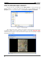
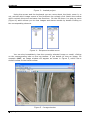
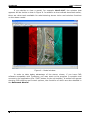
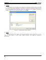
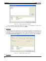
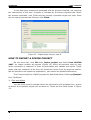
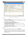
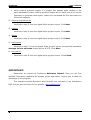
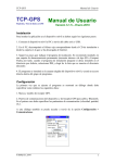
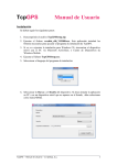
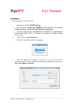
 TcpStereo
Version 1.1
August 2010
USER'S MANUAL
© Aplitop S.L. 2010
C/ Sumatra, 9 E-29190 MALAGA, SPAIN
www.aplitop.com
e-mail: [email protected]
TcpStereo
User's Manual
INTRODUCTION
This manual is a practical guide, helping you to open and create projects in
TcpStereo. For issues referring to the installation, set up and advanced areas, see the
Reference Manual.
Once you start up the program, a window will appear as shown in Figure 1:
Figure 1 – Main TcpStereo interface
From this point, you may:
•
Open an existing project and view it in TcpStereo.
•
Create a project using data imported from Digi3D.
•
Create a project using data imported from a digital photogrammetric flight.
To follow the examples,
(http://www.aplitop.com).
© Aplitop S.L. 2010
you
can
download
them
from
our
website
1
TcpStereo
User's Manual
HOW TO OPEN AND VIEW A PROJECT…
On the menu bar, click File and then Open project…. Via the window that
appears (Figure 2), locate and select the file (with a .pry extension) from the
Ejemplo1 project - the default location is C:\Proyectos TcpStereo\Ejemplo1.
Figure 2 – Select project.
After loading the project, TcpStereo will display a photogrammetric block which
constitutes images of the loaded project (Figure 3). The label Reduced mode
indicates that the project is using low-resolution images (see the importing of digital
photogrammetric flights).
© Aplitop S.L. 2010
2
TcpStereo
User's Manual
Figure 3 – Loaded project.
Using the mouse and the keyboard you can move about the block, zoom in or
out, and set which image comes to the forefront via a simple click. Notice the toolbar
which controls the zoom and save view functions. On the left there is a pop-up menu
(Figure 4) which allows you to view images and stereo models by double clicking on
the corresponding element.
Figure 4 – Strips and models menu.
You can also immediately view the currently selected image or model, clicking
on the corresponding tabs on the top toolbar. If you decide to view an image, for
example 1117, an image window will appear as shown in Figure 5, which has a
similar toolbar to the block toolbar.
Figure 5 – Image window
© Aplitop S.L. 2010
3
TcpStereo
User's Manual
If you decide to view a model, for example 1116-1117, the window that
appears will be similar to that in Figure 6. In addition to the toolbars described earlier,
there are other tools available for administering stereo vision and calculus functions
on the stereo model.
Figure 6 – Model window
In order to take better advantage of the stereo viewer, if you have CAD
software compatible with TcpStereo, you may start up the program in question and
connect to the application (the "CAD” button on the top toolbar). A toolbar will appear
showing CAD plotting and control options, the functions of which are also detailed in
the Reference Manual.
© Aplitop S.L. 2010
4
TcpStereo
User's Manual
HOW TO IMPORT A DIGITAL PHOTOGRAMMETRIC FLIGHT
On the menu bar, click File then Import project and finally From flight data.
An import window will appear (Figure 7) which will advance step by step where
interaction is required, in order to personalize and validate the import.
The 6 import steps for digital photogrammetric flight projects are described
below, following Ejemplo1 in TcpStereo.
1) Files and folders
You will firstly need to indicate where the information will be taken from, as well
as where the imported project will be saved to. These are the fields shown in Figure 7:
Figure 7 – Digital flight import, step 1.
INPUT:
•
•
Orientation file: Select the file from project Ejemplo1 from TcpStereo.
C:\Proyectos TcpStereo\Ejemplo1\Ejemplo1.exp
Image folder: Select the original image folder.
C:\Proyectos TcpStereo\Ejemplo1
OUTPUT:
•
Project name: Write Ejemplo1.
© Aplitop S.L. 2010
5
TcpStereo
User's Manual
•
Project folder: Route through which the project information required by
TcpStereo is saved. Bear in mind that the folder should exist, and that the
images will need quite a lot of free disc space. You should there ensure that you
have sufficient space on the chosen disc. In this case we will be using the same
folder as the imported project “C:\Proyectos TcpStereo\Ejemplo1”
IMAGES
•
•
Reduced resolution: allows you to import the project more rapidly, at the cost
of generating images with less resolution. You may later convert them to
maximum resolution image. You should check this option.
Full resolution: images are imported at maximum resolution, although this
involves a longer processing time. In this case, pyramid images created earlier
may be reused.
Click Next.
2) External orientation file
Once a list of photographs has been obtained along with their external
orientations based on entry data, the results are shown in the form of a table:
Figure 8 – Digital flight import, step 2.
Following our example, leave all fields as they are and click Next. In general, a
meaning should be assigned to the values in each column, using the tabs in the first
line. You should also indicate which is the column separator, and on which units you
have assigned rotation angles. You can also select the table entries you wish to
import.
© Aplitop S.L. 2010
6
TcpStereo
User's Manual
3) Images
In this step, the user selects the images to be imported. Notice that on the right
you can see the space available on the disc on which the project is saved as well
as the estimated space required, which will depend on the number of selected
images. Leave all the images selected and click Next.
Figure 9 – Digital flight import, step 3.
4) Models
Having selected the images, the program assesses what models they can be
used to form based on their order (photo number) and external orientation
parameters.
© Aplitop S.L. 2010
7
TcpStereo
User's Manual
Figure 10 – Digital flight import, step 4.
If the orientation data and images are correct, it is advisable to create all of
them. Leave all the models selected and click Next.
5) Parameters
This step serves as validation for the imported information. It is advisable to set
an average terrain elevation which is as accurate as possible, to ensure optimum
visualization of the photogrammetic block. Leave all parameters as they are,
except Average terrain height which you should set at 645.00, then click Next.
Figure 11 – Digital flight import, step 5.
6) Conversion
© Aplitop S.L. 2010
8
TcpStereo
User's Manual
In this final step images are generated and the project compiled, not requiring
the intervention of the user. Progress is indicated by the three progress bars. When
the process concludes, click Finish and the recently imported project will open. Once
the conversion process has finished, click Finish.
Figure 12 – Digital flight import, step 6.
HOW TO IMPORT A DIGI3D PROJECT
On the menu bar, click File then Import project and finally From DIGI3D
2007. An import window will appear (Figure 13) which will advance step by step
where interaction is required, in order to personalize and validate the import. These
steps, with the exception of the first, are identical to those from the previous section.
We will therefore not repeat the explanation, just outline the possible differences.
The 6 import steps for Digi3D projects are described below, following Ejemplo2
from TcpStereo.
1) Files and folders
You will firstly need to indicate where the information will be taken from, as well
as where the imported project will be saved to. These are the fields shown in Figure
13:
© Aplitop S.L. 2010
9
TcpStereo
User's Manual
Figure 13 – Digi3D import, step 1.
INPUT:
•
•
•
•
•
•
External orientation type: a suitable value should be set based on the data
available. Set as Single file….
Type of Project: this should indicate analog if the photographs have fiducial
marks or digital if not. Set as Analog
External orientations: external orientation file.
“C:\Proyectos TcpStereo\Ejemplo2\Ejemplo2.eo”
Internal orientations: folder in which the internal orientation files are located.
“C:\Proyectos TcpStereo\Ejemplo2”
Image folder: folder in which the original image files are located.
“C:\Proyectos TcpStereo\Ejemplo2”
Camera file: required for analog projects, Digi3D camera file camera
153.942.cam in the Ejemplo2 TcpStereo folder.
OUTPUT:
•
•
Project name: the name the user wishes to give. Use Ejemplo2
Project folder: Route through which the project information required by
TcpStereo is saved. Bear in mind that the folder should exist, and that the
images will need quite a lot of free disc space. You should there ensure that you
have sufficient space on the chosen disc. Leave this the same as the folder for
TcpStereo Ejemplo2.
© Aplitop S.L. 2010
10
TcpStereo
User's Manual
•
Using existing pyramid images: if a project has already been created in the
same destination folder, existing pyramid images will be valid, and it will not be
necessary to generate them again. Leave this unchecked the first time that you
follow this example.
2) External orientation file
Identical to step 2 from the digital flight project import. Click Next.
3) Images
Identical to step 3 from the digital flight project import. Click Next.
4) Models
Identical to step 4 from the digital flight project import. Click Next.
5) Parameters
Identical to step 5 from the digital flight project import, except that parameter
Average terrain elevation should be set at 275. Click Next.
6) Conversion
Identical to step 6 from the digital flight project import. Click Finish.
IMPORTANT:
Remember to consult the TcpStereo Reference Manual. Here you will find
detailed information regarding all aspects of the application, helping you to take full
advantage of the program.
The example projects Ejemplo1 and Ejemplo2 are included on the distribution
DVD and can also be found on our website (www.aplitop.com).
© Aplitop S.L. 2010
11