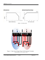
1
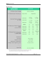
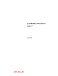
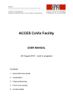
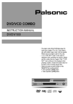
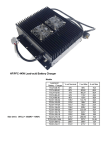
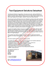
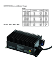
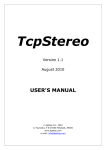
SPECTRA
ENGINEERING
MXPS700 Series
User Manual
MXPS700 Series
Spectra Engineering Pty Ltd
ABN 65 057 696 438
731 Marshall Road
Malaga
Western Australia 6090
Tel: +61-8-92482755
Fax: +61-8-92482756
Email: [email protected]
Web: www.spectraeng.com.au
In order to continually improve our products, Spectra Engineering Pty Ltd reserves the right to alter,
without notice and at any time, the equipment and specifications described in this document.
All performance figures quoted are typical and are subject to normal manufacturing and service
tolerances.
The purchaser is warned that some statements made in this document may be inaccurate due to
typographical or other errors or subsequent modifications of the product. While every care has been
taken in the creation of this document, no warranty of accuracy or reliability is given, in any advice or
information contained in this document. Spectra Engineering Pty Ltd or any director, officer, agent or
employee of Spectra Engineering Pty Ltd cannot be held liable for any loss or damage whatsoever
arising in any way or any representation, act or omission whether express or implied (including
responsibility to any person by reason of negligence).
Copyright © Spectra Engineering Pty Ltd 2012.
This work is copyright. Other than as permitted by Law, no part of it may be reproduced, stored in a
retrieval system or transmitted in any form or by any process without prior written permission.
FCC Interference Warning
Note: The equipment has been tested and found to comply with the limits for a class B digital device,
pursuant to Part 15 of the FCC Rules. These limits are designed to provide reasonable protection against
harmful interference when the equipment is operated in a commercial or residential environment. This
equipment generates, uses and can radiate radio frequency energy. If not installed and used in
accordance with this instruction manual, may cause harmful interference to radio communication.
© 2012 Spectra Engineering Pty Ltd
Ver1.0
Page 2 of 9
MXPS700 User Manual
SAFETY SUMMARY
The MXPS700 power supply, contains dangerous mains voltages within.
For servicing, please return to your nearest distributor. No fuses or user-serviceable parts are
within the power supply module.
The following general safety precautions as would normally apply, should be observed
during all phases of operation, service and repair of this equipment.
CAUTION Risk of Electrical Shock.
AROUND THE EQUIPMENT
This product is a Safety Class 1 instrument. To minimise any possible shock hazard
from power supply or lightning strike, the instrument chassis must be connected to
an electrical ground. The instrument must be connected to the AC power supply
mains through a three conductor power cable, with the ground wire firmly connected
to an electrical ground (safety ground) at the power outlet. For instruments
designed to be hard-wired to the supply mains, the protective earth terminal must
be connected to the safety electrical ground before another connection is made.
Any interruption of the protective ground conductor, or disconnection of the
protective earth terminal will cause a potential shock hazard that might cause
personal injury.
Provide adequate ventilation around the rear of the equipment.
DO NOT OPERATE IN AN EXPLOSIVE ATMOSPHERE
Do not operate the equipment in the presence of flammable gases or fumes. Operation of
any electrical equipment in such an environment constitutes a definite safety hazard.
DO NOT ATTEMPT INTERNAL SERVICEING
Operating personnel must not remove the instrument cover. No internal adjustment or
component replacement is allowed by non-Spectra qualified personnel. Never replace
components with power cable connected. To avoid injuries, always disconnect power ,
discharge circuits and remove external voltage source before touching components.
DO NOT SUBSTITUTE PARTS OR MODIFY THE EQUIPMENT
Because of the danger of introducing additional hazards, do not install substitute or lower
voltage parts to the equipment. Return to your authorised distributor.
© 2012 Spectra Engineering Pty Ltd
Ver1.0
Page 3 of 9
MXPS700 User Manual
WARRANTY CONDITIONS & PRECAUTIONS
This MXPS700 product is warranted against defects in materials and workmanship for a
period of 1 years from date of shipment .During the warranty period, Spectra Engineering
will, at it’s option, either repair or replace products which prove to be defective.
The warranty shall not apply to defects resulting from improper or inadequate usage or
maintenance by the buyer, buyer supplied products or interfacing. Furthermore, Spectra
Engineering does not warrant any damage occurring as a result of the buyer’s circuitry or
the buyer’s - supplied products.
The following conditions are not covered by the warranty. Please ensure that the MXPS700
is not subject to;
1. Over voltage or Reverse Power Supply Voltage.
Do not use AC supply which exceeds the input voltage and frequency rating of this
instrument. The input voltage and frequency rating of the power supply series is: 85VAC
to 265VAC, 50/60Hz. For safety reasons, the mains supply voltage fluctuations should
not exceed +/-10% of nominal voltage.
2. Operation in locations subject to abnormal environmental conditions such as extreme
temperatures or ingress of moisture or excessively dusty environments.
© 2012 Spectra Engineering Pty Ltd
Ver1.0
Page 4 of 9
MXPS700 User Manual
• 1RU rack mountable.
Introduction
This user’s manual contains the operating
instructions, installation instructions and
specifications of the MXPS700 power supply
series.
This versatile 1RU switch mode power supplies
come in a rugged sturdy compact construction
metal case, made to withstand harsh industrial
environments.
• Low radiated emissions due to double metal
housing.
Turning the power supply ON/OFF
The power supply has an on/off switch located
on the rear, marked “I” for ON and “O” for OFF.
Turn the power supply on, by pressing the “I”
side of the switch.
The MXPS700 has a number of flexible
configurations. These include the following
models:
Turning the power supply off, by press the “O”
side of the power switch.
•
Connecting the Power Supply to
Peripherals
•
•
MXPS700A – 13V8DC, 2X 330W
Suitable for 6X MX800 50W TX or 4x 100W
VHF/UHF TX.
MXPS700B – 28VDC, 2X 335W
Powers 1x 200/300 Watt Power Amplifier.
MXPS700C –13V8DC (330W) & 28VDC
(335W)
Powers 2X MX800 100 Watt 700/800MHz.
All models accept a wide mains voltage swings
85 to 264 VAC input voltage for worldwide use.
* Input mains fuse may require to be changed to 10amp if
used on 110VAC.
When increased current is the goal, the ideal
situation is to have the total load current split
evenly across the two parallel ports.
The total equipment current draw will determine
whether ports A & B required to be paralleled or
not. See Parallel ports & Redundant Power
Supply System section for more information.
Please insure the connecting equipment doesn’t
exceed the Max Output Current (MOC)
requirements. See specification section below.
Features
Select a suitable gauge of the DC cable to
ensure less than 0.5V volt drop at a maximum
current draw of the connecting equipment.
• Protected against mains surges, spikes and
brown outs.
Unplug the MXPS700 from the mains supply
outlet.
• Tolerant of high temperatures and vibration.
Using the rear screw terminal connector,
connect your DC cable, insuring the correct
polarity. (+Ve) RED wire to the positive terminal
pin and connect the negative (-Ve) Red with
black or black wire to the negative terminal.
• Protected against short circuit, “Current
Limiting Circuit”. If the peak current rating is
exceeded due to a short circuit or excessive
load across the output terminals, the output
current will be limited to a safe level,
preventing damage to the power supply
• Over temperature protection.
Please see rear layout label, for screw terminal
polarity and connections.
See example Figure 2 & 3.
• Output over voltage shutdown. Induced
output transient protected.
It is also recommend fitting an inline fuse holder
in series with the positive, between to equipment
and power supply.
• Manufactured using only well specified and
qualified high grade commercial parts.
Connect the appropriate plug to suit your
radio/equipment on other end of the DC cable.
• Infant mortality burn in period.
Then plug the mains power cable into the mains
supply outlet and switch it on.
• Easy to wire screw terminal output ports.
Turn power supply ON. Insure power led lights
on radio. If no power led lights, turn OFF power
supply and recheck cabling.
• AC input via covered IEC connector.
• Compliant with relevant international
standards.
• Thermostatically controlled cooling fan.
• Output short circuit protected no minimum
load current.
© 2012 Spectra Engineering Pty Ltd
Ver1.0
Page 5 of 9
MXPS700 User Manual
Cooling
The MXPS700 power supply provides cooling by
convection and forced air cooling. This
increases the normal airflow around the power
supply in combination with a speed controlled
fan to improve cooling at higher levels of use.
A
+Ve
B
-Ve
+Ve
-Ve
Caution: Place the power supply in a well
ventilated and cool area. Do not block the
ventilation openings on left & right sides of the
unit.
Mounting
The MXPS700 design allows flexible mounting
when used in conjunction with Spectra
Engineering base stations / repeaters/ RF power
amplifiers. The design allows it to be installed in
a 1RU rack mount and it also can be installed at
a distance from the base station / repeater if
required.
Parallel ports & Redundant Power
Supply System
In many applications it is desirable to connect
both ports A & B terminals in parallel. This may
be done to increase the total current available or
for redundancy.
To Radio / Equipment
Figure 1, Paralleling A & B DC outputs.
Troubleshooting
Radio didn’t power up when power supply
was turned on.
The MXPS700A / B models can be configured
for paralleled & redundant configurations.
Probable cause 1: No power in the AC outlet,
or the main input fuse inside power supply
mains (IEC) connector has blown.
The design achieves this by incorporating two
separate main block supplies, thus allowing the
DC ports to be connected in parallel via the rear
screw terminal block.
Suggested solution: Check the mains power
outlet, or replace the mains input fuse inside the
unit (5 Amp fuse rating).
Proper load sharing can only be accomplished
when the output voltage of the supplies are at
the same level at the point where they are
common. This means that voltage drop in the
wiring must also be taken into account.
Multiple Units can be paralleled however
Temperature fluctuation, component tolerances,
and power supply location (i.e. wire lengths) are
some of the factors that can influence the output
voltage and thus effect the load sharing.
Redundancy is achieved when ports A & B are
paralleled. If one of the main supply blocks ports
should fail, and the maximum required current is
half of MOC, the remaining working supply block
will provide power to the load (equipment).
Probable cause 2: The unit is in current limiting
condition or blown output fuse.
Suggested solution: Disconnect radio and
check that the output terminals have not shortcircuited and are have correct polarity.
Verify this fault condition with a multimeter.
Check in line fuses..
Fuse blows when power is turned on.
Probable cause: Unit is defective.
Suggested solution: Call technical support.
The MXPS700C can not be configured to work
in paralleled & redundant configurations, as it is
limited to MOC, due to its split supply rail
configuration, (13V8 and 28VDC).
© 2012 Spectra Engineering Pty Ltd
Ver1.0
Page 6 of 9
MXPS700 User Manual
Specifications
Power Supply
Specifications
MXPS700
AC Mains Input Voltage
85VAC to 264VAC
* AC Mains Input Current typ. 10A@115VAC
Nominal Output Voltage
@ 1Amp
5A@240VAC
Model
Output A
Output B
MXPS700A
13.8VDC
+/- 0.2V
13.8VDC
+/- 0.2V
MXPS700B
28VDC
+/- 0.2V
28VDC
+/- 0.2V
MXPS700C
13.8VDC
+/- 0.2V
28VDC
+/- 0.2V
Model
DC Maximum Output Current
(MOC)
Output
A
MXPS700A
24A
24A
48A
Continuous at 25°C
MXPS700B
12A
12A
24A
MXPS700C
24A
12A
N/A
Model
DC Rated Output Current @
Max Temp
Output
A
MXPS700A
22A
22A
44A
Continuous at 60°C
MXPS700B
11A
11A
22A
MXPS700C
22A
11A
N/A
Regulation
Output Paralleled
B
Outputs
Output Paralleled
B
Outputs
+/- 100mV
Efficiency
>80% typical
Ripple & Noise
< 20mV RMS
Operating Temperature
-30°C to 60°C
Design Field Lifetime (MTBF)
Power Factor
10 years @ 50°C
Auto Power Factor Correction
Weight
Approvals
TBA
C-Tick, CE, UL, TUV,
CB, CUL, S-MARK
Due to ongoing development we reserve the right to alter specifications without notice.
* Input mains fuse may require to be changed to 10amp if used on 110VAC.
© 2012 Spectra Engineering Pty Ltd
Ver1.0
Page 7 of 9
MXPS700 User Manual
Figure 2 – De-rating Cures
A
+Ve
B
-Ve
-Ve
+Ve
Output A1
Output A2
Output B2
Output A3
Output B3
Output B1
Figure 3 – Rear View of Output Ports A & B Connection Terminals.
(See Specifications for current capacity of ports)
© 2012 Spectra Engineering Pty Ltd
Ver1.0
Page 8 of 9
MXPS700 User Manual
Figure 4 – MXPS700C Rear View.
Figure 5 – MXPS700 Right Hand Side View
© 2012 Spectra Engineering Pty Ltd
Ver1.0
Page 9 of 9