1
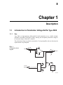
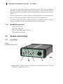
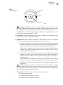
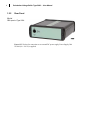
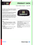
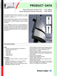
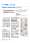
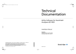
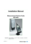
Technical Documentation Polarization Voltage Buffer Type 5008 HEADQUARTERS: Brüel & Kjær Sound & Vibration Measurement A/S · DK-2850 Nærum · Denmark Telephone: +45 7741 2000 · Fax: +45 4580 1405 · www.bksv.com · [email protected] Local representatives and service organisations worldwide ËBE-1858---UÎ User Manual English BE 1858 – 11 Polarization Voltage Buffer Type 5008 User Manual BE 1858-11 May 2013 Safety Considerations This apparatus has been designed and tested in accordance with IEC/EN 61010 – 1 and ANSI/UL 61010 – 1 Safety Requirements for Electrical Equipment for Measurement, Control and Laboratory Use. This manual contains information and warnings which must be followed to ensure safe operation and to retain the apparatus in safe condition. Special note should be made of the following: Safety Symbols The apparatus will be marked with this symbol when it is important that you refer to the associated warning statements given in the manual. Protective Earth Terminal Hazardous Voltage Explosion Hazard The equipment is not designed to be used in potentially explosive environments. It should not be operated in the presence of flammable liquids or gases. Warnings • • • Switch off all power to equipment before connecting or disconnecting their digital interface. Failure to do so could damage the equipment Whenever it is likely that the correct function or operating safety of the apparatus has been impaired, it must be made inoperative and be secured against unintended operation Any adjustment, maintenance and repair of the open apparatus under voltage must be avoided as far as possible and, if unavoidable, must be carried out only by trained service personnel • Do not dispose of electronic equipment or batteries as unsorted municipal waste • It is your responsibility to contribute to a clean and healthy environment by using the appropriate local return and collection systems • Hazardous substances in electronic equipment or batteries may have detrimental effects on the environment and human health • The symbol shown to the left indicates that separate collection systems must be used for any discarded equipment or batteries marked with that symbol • Waste electrical and electronic equipment or batteries may be returned to your local Brüel & Kjær representative or to Brüel & Kjær Headquarters for disposal Copyright 2013, Brüel & Kjær Sound & Vibration Measurement A/S All rights reserved. No part of this publication may be reproduced or distributed in any form, or by any means, without prior written consent from Brüel & Kjær Sound & Vibration Measurement A/S, Nærum, Denmark Contents CHAPTER 1 Description.......................................................................................................... 1 1.1 1.2 Introduction to Polarization Voltage Buffer Type 5008......................................... 1 Sockets and Controls........................................................................................... 2 CHAPTER 2 Operation............................................................................................................. 5 2.1 2.2 Connections ......................................................................................................... 5 Settings ................................................................................................................ 7 CHAPTER 3 Service and Repair ............................................................................................. 9 CHAPTER 4 Specifications ................................................................................................... 11 1 Chapter 1 Description 1.1 Introduction to Polarization Voltage Buffer Type 5008 1.1.1 Use Type 5008 is a high-impedance differential DC buffer intended to act as a buffer for highimpedance microphone polarization voltage, allowing the microphone polarization voltage to be measured using a common DC voltmeter. The polarization voltage can either be measured in a 7-pin preamplifier socket or directly at the input terminal of a preamplifier. Fig.1.1 Configuration block diagram V+ Input + Output – V– V+ +12 V 12 V DC Supply 0 V Re f. 200 V –12 V V– 130150 2 Polarization Voltage Buffer Type 5008 – User Manual The input stage of Type 5008 is made with a field-effect transistor (FET) operational amplifier, which has an extremely high input impedance and an ultra-low input bias current. The zero point of the plus and minus supply to the operational amplifier is connected to the reference voltage. The built-in 200 V reference voltage is made by a regulator that includes a low-drift reference and a low-drift operational amplifier with low-drift resistors in the feedback loop. The output of Type 5008 can be configured to deliver the absolute level of the measured voltage or the difference of the measured voltage from the reference voltage. 1.1.2 Included Accessories • Probe Cable WL-1272 • BNC Adaptor UA-1435 • BNC to 7-pin LEMO Adaptor WJ-0365 • Power Supply Unit ZG-0864 1.2 Sockets and Controls 1.2.1 Front Panel Fig.1.2 Front panel of Type 5008 2 1 3 4 5 1) Input socket: A BNT socket for connecting the enclosed probe cable. The input impedance is approximately 1015 . CHAPTER 1 Description Fig.1.3 Socket diagram 3 Screen Guard Centre pin 130152 Warning: Hazardous live voltage. The guard of the input socket delivers a voltage equivalent to the polarization voltage tested through a 220 k impedance. This means that the voltage can be up to 210 VDC and the current is limited to approximately 1 mA. 2) Ovl. indicator: A red LED that lights when the polarization voltage being tested exceeds the reference voltage by more than ±10 VDC 3) On indicator: A green LED that lights when power is connected to the instrument and the V Ref. switch is set to anything other than Off 4) Output socket: A BNT socket for connecting to a DC voltmeter (see Fig.1.3 for diagram) The voltmeter can be connected to the output socket in one of two ways: a) Connect the voltmeter’s low terminal to the screen of the output socket and its high terminal to the centre pin of the output socket. In this case, the indication on the voltmeter will be the absolute value of the polarization voltage being tested. This method is recommended if the accuracy of the voltmeter is higher than the accuracy of the reference voltage (the accuracy of the built-in 200 V reference voltage is approximately 0.015%). b) Connect the voltmeter’s low terminal to the guard of the output socket and its high terminal to the centre pin of the output socket. In this case, the indication on the voltmeter will be the difference of the polarization voltage being tested from the reference voltage. This method is recommended if the accuracy of the voltmeter is lower than the accuracy of the reference voltage. If this method is used to make sure that the low terminal of the voltmeter is not connected to the ground of the polarization voltage being tested. Warning: Hazardous live voltage. The guard of the output socket delivers a voltage equivalent to the selected reference voltage. For the built-in 200 V reference voltage the current is limited to 0.6 mA. The centre pin of the output socket delivers a voltage of up to 210 VDC and the current is limited to 0.6 mA. 5) V Ref. switch: 3-position switch for selecting the reference voltage: Off: Switch off the instrument 0 V: Set the reference voltage to zero volts 200 V: Set the reference voltage to 200 volts 4 Polarization Voltage Buffer Type 5008 – User Manual 1.2.2 Rear Panel Fig.1.4 Rear panel of Type 5008 Power 12 V: Socket for connection to an external DC power supply. Power Supply Unit ZG-864 (90 – 264 V) is supplied. 5 Chapter 2 Operation To perform the measurement of a polarization voltage, you need the following: • Polarization Voltage Buffer Type 5008 • Adaptor for connection to a microphone preamplifier or directly to the measuring instrument. The following adaptors are supplied with Type 5008: BNC Adaptor UA-1435 BNC to 7-pin LEMO Adaptor WJ-0365 • Probe Cable WL-1272 (supplied with Type 5008) • DC voltmeter UA-1435 is used to measure the polarization voltage of a ½ microphone preamplifier and WJ-0365 is used for measuring the polarization voltage in the 7-pin LEMO socket of a measuring instrument. 2.1 Connections The DC voltmeter can be connected in two ways depending on the purpose of the measurement: • Measuring the absolute voltage: This method is recommended if a high precision DC voltmeter is used for the measurement • Measuring the deviation of the polarization voltage from the reference voltage: This method is recommended if a low precision DC voltmeter is used for the measurement See below for connection instructions according to the required method/measurement type. 2.1.1 Connections with Absolute Measurements 1) Connect UA-1435 to the preamplifier (or WJ-0365 to the 7-pin LEMO socket). 2) Connect Probe Cable WL-1272 between the adaptor and the input of Type 5008. 3) Connect the DC voltmeter to the output socket of Type 5008: a) The low terminal of the DC voltmeter connects to the screen of the output socket. 6 Polarization Voltage Buffer Type 5008 – User Manual b) The high terminal of the DC voltmeter connects to the centre pin of the output socket. See Fig.2.1 for connection diagram. Warning: Hazardous live voltage. The guard of the output socket delivers a voltage equivalent to the selected reference voltage. For the built-in 200 V reference voltage, the current is limited to 0.6 mA. The centre pin of the output socket delivers a voltage of up to 210 VDC and the current is limited to 0.6 mA. Fig.2.1 Connecting Type 5008 with a DC voltmeter when performing absolute measurements 5008 Polarization Voltage Buffer WL-1272 Probe Cable Preamplifier Input Output On UA-1435 Adaptor + 200.1427 Ovl. V DC V Ref. 200V — 0V — Off — HI LO DC Voltmeter 130154 2.1.2 Connections with Relative Measurements Please note that the use of this method requires that the DC voltmeter is floating in respect to the rest of the setup. 1) Connect UA-1435 to the preamplifier (or WJ-0365 to the 7-pin LEMO socket). 2) Connect Probe Cable WL-1272 between the adaptor and the input of Type 5008. 3) Connect the DC voltmeter to the output socket of Type 5008: a) The low terminal of the DC voltmeter connects to the guard of the output socket. b) The high terminal of the DC voltmeter connects to the centre pin of the output socket. See Fig.2.2 for connection diagram. CHAPTER 2 Operation 7 Warning: Hazardous live voltage. The guard of the output socket delivers a voltage equivalent to the selected reference voltage. For the built-in 200 V reference voltage, the current is limited to 0.6 mA. The centre pin of the output socket delivers a voltage of up to 210 VDC and the current is limited to 0.6 mA. Fig.2.2 Connecting Type 5008 with a DC voltmeter when performing relative measurements 5008 Polarization Voltage Buffer Input WL-1272 Probe Cable Preamplifier Ovl. On UA-1435 Adaptor Output V Ref. 200V — 0V — Off — mV + 14.3 DC LO DC Voltmeter 2.2 HI 130155 Settings The reference voltage can be set to 0 V or to its built-in, high precision reference voltage of 200 V. Use the V Ref. switch on the front panel to set the reference voltage. Type 5008 can measure voltages in the range of ±10 V referred to the selected reference voltage. 8 Polarization Voltage Buffer Type 5008 – User Manual 9 Chapter 3 Service and Repair Polarization Voltage Buffer Type 5008 is designed and constructed to provide many years of reliable operation. However, if a fault occurs that impairs its correct function and operating safety, disconnect the Voltage Buffer immediately from its power source and remove it from your instrument setup to secure against unintended operation and the risk of further damage. For repair, contact your local Brüel & Kjær service representative. Under no circumstances should repair be attempted by persons not qualified in servicing electronic instrumentation. 10 Polarization Voltage Buffer Type 5008 – User Manual 11 Chapter 4 Specifications The following specifications are based on a 1-year calibration cycle, an operating temperature of 18 to 28°C (64 to 82°F), a relative humidity up to 90%, a warm up time of 10 minutes, operation in a controlled environment and length of signal cables less than 2 metres. OUTPUT IMPEDANCE OF GUARD IN THE INPUT CONNECTOR 220 k The specifications are for an estimated confidence level of not less than 95% SUSCEPTIBILITY TO RADIATED ELECTROMAGNETIC FIELDS AND TO CONDUCTED RFDISTURBANCES ON AC SUPPLY AND SIGNAL CABLES <50 mVp introduced to output <25 mVDC introduced to output REFERENCE VOLTAGE SETTINGS 0 V or 200 V MEASUREMENT RANGE ±10 V referred to the reference voltage BASIS ACCURACY 0 V Reference Setting: ±0.01 V 200 V Reference Setting: ±0.03 V OUTPUT IMPEDANCE (OUTPUT CONNECTOR) Centre Pin: <0.1 , <1.5 mA Guard: 2 k, <0.6 mA DC POWER 12 V 0.2 A INPUT IMPEDANCE Approximately 1015 DIMENSIONS Height: 35 mm (1.48 in) Width: 110 mm (4.33 in) Depth: 145 mm (5.71 in) INPUT BIAS CURRENT ±0.2 pA WEIGHT 300 g (10.58 oz) 12 Polarization Voltage Buffer Type 5008 – User Manual Compliance with Standards CE-mark indicates compliance with: EMC Directive and Low Voltage Directive. C-Tick mark indicates compliance with the EMC requirements of Australia and New Zealand. China RoHS mark indicates compliance with administrative measures on the control of pollution caused by electronic information products according to the Ministry of Information Industries of the People’s Republic of China. Safety EN/IEC 61010–1: Safety requirements for electrical equipment for measurement, control and laboratory use. ANSI/UL 61010–1: Safety requirements for electrical equipment for measurement, control and laboratory use. EMC Emission EN/IEC 61000–6–3: Generic emission standard for residential, commercial and light industrial environments. EN/IEC 61000–6–4: Generic emission standard for industrial environments. CISPR 22: Radio disturbance characteristics of information technology equipment. Class B Limits. FCC Rules, Part 15: Complies with the limits for a Class B digital device. This ISM device complies with Canadian ICES-001 (interference causing equipment standard). EMC Immunity EN/IEC61000–6–1: Generic standards – Immunity for residential, commercial and light industrial environments. EN/IEC 61326: Electrical equipment for measurement, control and laboratory use – EMC requirements. Note: The above is only guaranteed using accessories listed in this manual. Temperature IEC 60068–2–1 & IEC 60068–2–2: Environmental Testing. Cold and Dry Heat. Operating Temperature: +15 to +35C (+59 to +95F) Storage Temperature: –25 to +70C (–13 to +158F) Humidity IEC 60068–2–78: Damp Heat: 93% RH (non-condensing at 40C (104F)). Mechanical Non-operating: IEC 60068–2–6: Vibration: 0.3 mm, 20 ms–2, 10–500 Hz IEC 60068–2–27: Shock: 1000 ms–2 IEC 60068–2–29: Bump: 1000 bumps at 400 ms–2 Enclosure IEC 60529 (1989): Protection provided by enclosures: IP 20 Brüel & Kjær reserves the right to change specifications and accessories without notice Technical Documentation Polarization Voltage Buffer Type 5008 HEADQUARTERS: Brüel & Kjær Sound & Vibration Measurement A/S · DK-2850 Nærum · Denmark Telephone: +45 7741 2000 · Fax: +45 4580 1405 · www.bksv.com · [email protected] Local representatives and service organisations worldwide ËBE-1858---UÎ User Manual English BE 1858 – 11