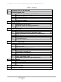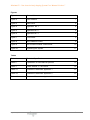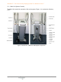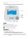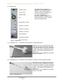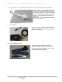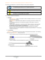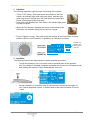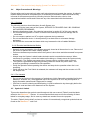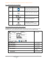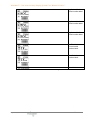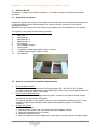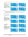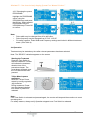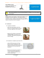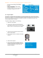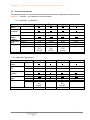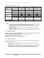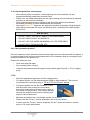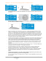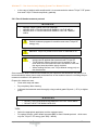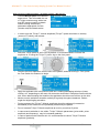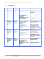
1
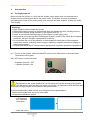
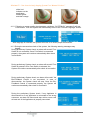
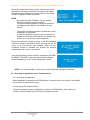
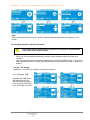
Non-invasive body shaping System
USER MANUAL
Pollogen’s Proprietary Information
Version 7.0 May 1, 2012
P/N 11600400 / Pollogen Ltd. / May 2012
Maximus™ - Non-invasive body shaping System User Manual Version 7
Pollogen Ltd. reserves the right to make changes without notice to its products or specifications to
improve performance, reliability, or manufacturability.
All information supplied by Pollogen Ltd. is believed to be accurate and reliable. However,
Pollogen Ltd. assumes no responsibility for its use. No license is hereby granted by its implication
or otherwise under any patent or patent rights of Pollogen Ltd.
This document, in part or entirety, is not to be produced, reproduced or transmitted in any form or
by any means, electronic or mechanical, for any purpose, without the express written permission
of Pollogen Ltd.
Pollogen Ltd. has patents and pending patent applications, trademarks,
copyrights, and/or other intellectual property rights covering the subject matter in this document.
Providing of this document does not give any license to these
patents, trademarks, copyrights, and/or other intellectual property rights unless otherwise
expressly provided in any written agreement from Pollogen Ltd.
All data is subject to change without prior notification.
Pollogen Ltd., 6 Kaufman St., PO Box 50320, Tel Aviv 68012 Israel
Obelis S.A,, Boulevard Général Wahis 53 1030 Brussels, BELGIUM
Tel: 32 (0) 2 732 5954, Fax: 32 (0) 2 732 6003, GSM 32 47545 4660,
e-mail: [email protected]
Contact Information
Customer satisfaction is a Pollogen priority. To help us in providing you with the best possible
product and support, please send us your comments and suggestions. Contact us at the details
below:
Pollogen Ltd.
6 Kaufman St., Gibor House
PO Box 50320
Tel Aviv, Israel 68012
Telephone:
Facsimile:
Web Site:
Email:
+972 3 510 4110
+972 3 510 4112
www.pollogen.com
www.tripollar.com
[email protected]
Proprietary Information of
2
Maximus™ - Non-invasive body shaping System User Manual Version 7
Table of Contents
1.
INTRODUCTION TO THE SYSTEM
2.
SYSTEM DESCRIPTION
2.1
SYSTEM COMPONENTS AND CONTROLS
2.2
TECHNICAL SPECIFICATIONS
2.3
SAFETY FEATURES
2.4
MAJOR PRECAUTIONS & WARNINGS
2.5
SYMBOLS & LABELS
5
5
10
11
14
14
3.
INITIAL SET UP
3.1
UNPACKING THE SYSTEM
3.2
GENERAL INSTALLATION REQUIREMENTS
3.3
PREPARATION FOR OPERATION
17
17
17
18
4.
USER INTERFACE
4.1
TURNING SYSTEM ON
4.2
CHOOSING APPLICATOR & TREATMENT AREA
4.3
HOW TO CHANGE SYSTEM DEFAULT PARAMETERS
4.4
OPERATION
4.5
INDICATIONS
4.6
PROGRAM UPDATE
4.7
TURNING SYSTEM OFF
22
22
24
25
27
28
29
30
5.
MAXIMUS TREATMENT
5.1
INDICATION FOR USE
5.2
CONTRAINDICATIONS
5.3
PRECAUTIONS
5.4
PRE-TREATMENT PREPARATION
5.5
POSSIBLE SIDE EFFECTS
5.6
TREATMENT PARAMETERS
5.7
TREATMENT PROGRAMS
5.8
TREATMENT PROCEDURES
5.9
POST TREATMENT CARE
6
TREATMENT PROTOCOL AND CONCLUSION
31
31
31
32
32
32
33
34
34
40
40
7.
MAINTENANCE
7.1
SYSTEM CLEANING
7.2
APPLICATOR CLEANING
7.3
ORANGE CUPS CLEANING
40
40
40
40
8.
TROUBLESHOOTING
41
9.
WARRANTY TERMS
44
Proprietary Information of
5
3
Maximus™ - Non-invasive body shaping System User Manual Version 7
Figures
Figure 1
General View
6
Figure 2
User Interface
7
Figure 3
Back Panel
8
Figure 4
Applicator No. 1
8
Figure 5
Applicator No. 2
8
Figure 6
Applicator No. 3
9
Figure 7
Foot Switch
9
Figure 8
Bio-Feedback Control
9
Figure 9
Non Contact Infrared Thermometer
10
Figure 10
Unpacking the System
17
Table 1
Technical Specifications
10
Table 2
Explanation of User Manual Symbols
15
Table 3
Labels Affixed To The Device
16
Table 4.1
Treatment Parameters Applicator 1
33
Table 4.2
Treatment Parameters Applicator 2
33
Table 4.3
Treatment Parameters Applicator 3
34
Tables
Proprietary Information of
4
Maximus™ - Non-invasive body shaping System User Manual Version 7
1. INTRODUCTION
The Maximus™ system is intended for use in general dermatologic procedures.
The Maximus™ system is indicated for use in dermatologic procedures for
non-invasive body shaping, skin tightening, reduction of cellulite and treatment of wrinkles using
the Combination of TriLipo™ RF energy and TriLipo™ Muscle energy.
Intended place of the device: Clinics & Hospitals. Intended users: Healthcare professionals
I.E. Doctors & Nurses and subject to the local regulations.
Maximus™ consists of 6 main parts: Main Unit, Applicator No. 1 for the treatment of large body
areas , Applicator No. 2 for the treatment of medium size body areas and face, Applicator No. 3
for the treatment of very small facial areas and hands, Foot Switch and Bio Feedback Control.
The operator can adjust all system parameters from the user interface screen on the front panel.
2.
SYSTEM DESCRIPTION
This chapter provides a detailed description of the Maximus™ system, including its main
components, controls, and technical specifications. Please review this chapter carefully to
familiarize yourself with the controls, ports and connectors used during treatment.
2.1
System Components and Controls
The Maximus™ system consists of the following main components:
•
Main Unit (System Console)
•
Applicator No. 1 intended for the treatment of large body areas
•
Applicator No. 2 intended for treatment of medium size body areas and face
•
Applicator No. 3 intended for treatment of very small facial areas and hands.
•
Foot Switch
•
Bio-Feedback Control
•
Applicator holder
•
Cable holders (3 pcs)
•
Non Contact Infrared Thermometer
Proprietary Information of
5
Maximus™ - Non-invasive body shaping System User Manual Version 7
2.1.1 Main Unit (System Console)
The Main Unit controls the operation of the entire system (Figure 1). It contains the following
parts:
Figure 1: General View – Maximus™ Main System Components
Proprietary Information of
6
Maximus™ - Non-invasive body shaping System User Manual Version 7
2.1.2 Control Panel:
The Control Panel serves as the user interface and is located on the top of the Main Unit.
The Control Panel includes Graphic LCD, 4 function keys and regulation Jog (button).
Figure 2: User Interface – Control panel
Function Keys
- BACK key returns to previous screen
- Scroll DOWN key chooses a parameter on the screen
- Scroll UP key chooses a parameter on the screen
- OK key activates selected function/parameter
- Regulation Jog (Button) change TriLipo Power
User Interface Options
The MENU allows the following operations:
•
•
•
•
Choose Applicator – Applicator No. 1, 2 or 3.
Choose Treatment Area – face, neck, arms, tummy, buttocks, thighs or hands
Change RF Treatment Parameters of TriLipo™ RF energy :Time and power setting
Change Treatment Parameters of TriLipo™ Muscle energy: frequency, pulse width settings.
Proprietary Information of
7
Maximus™ - Non-invasive body shaping System User Manual Version 7
2.1.3 Back Panel
The Back Panel includes the
placement of the applicator holder,
ON/OFF switch, Bio-Feedback
Control connector, Applicator no. 1
connector, Applicator no. 2
connector, Application no. 3
connector, device S/N label, Foot
Switch connector, power inlet with
fuses and program plug.
Figure 3 – Back Panel
2.1.4 Applicator No. 1 - intended for the treatment of large body areas:
Applicator No. 1is connected to the main
unit using a cable comprised of electrical
wires and a connector. It is also consists of
a plastic body with an integrated electronic
system, 6 electrodes and indication light
guide ring.
When not in use, the applicator should be
stored in its cradle.
Figure 4 - Applicator No. 1
2.1.5 Applicator No. 2 - intended for the treatment of medium size body areas and face.
Applicator No. 2 is connected to the main
unit using a cable comprised of electrical
wires and a connector. It is also consists of
a plastic body with an integrated electronic
system, 3 electrodes and indication light
guide ring.
When not in use, the applicator should be
stored in its cradle.
Figure 5 - Applicator No. 2
Proprietary Information of
8
Maximus™ - Non-invasive body shaping System User Manual Version 7
2.1.6 Applicator No. 3 - intendeds for the treatment of very small facial areas and hands:
Applicator No. 3 is connected to the main
unit using a cable comprised of electrical
wires and a connector .It’s also consists of
a plastic body with an integrated electronic
system, 3 electrodes and indication light
guide ring.
When not in use, the applicator should be
stored in its cradle.
.
Figure 6 - Applicator No. 3
2.1.7 Foot Switch
The Foot Switch is used for system activation
upon press. The Foot Switch is supplied with
cable and connector.
Figure 7 – Foot Switch
2.1.8 Bio-Feedback Control:
The Bio-Feedback Control is used as a
patient control in the case of discomfort. It
consists of a plastic body with button, Velcro
strip and cable with connector.
Figure 8 - Bio-Feedback Control
Proprietary Information of
9
Maximus™ - Non-invasive body shaping System User Manual Version 7
2.1.9 Non Contact Infrared Thermometer:
Figure 9: Non Contact Infrared Thermometer
Infrared thermometer (Figure 9),
measures the surface temperature of the
skin.
An optical component of the unit collects
energy emitted reflected and transmitted
and focuses it onto a detector. Then an
electronic component translates the
information into a temperature reading
which is displayed on the thermometer.
The laser is used for aiming purpose only.
Please note that calibration is required
yearly and is within your responsibilities.
Pollogen do not calibrate or follow up
thermometers calibration.
2.2
Technical Specifications
Parameter
Input voltage
Mode of operation
Maximum output power RF
Output frequency RF
Output power control RF
TriLipo™ pulse duration
TriLipo™ pulse frequency
TriLipo™ pulse amplitude*
Programs
Weight
Dimensions
Value/Data
100-240 Volt, 50-60Hz, max 2.2A
TriLipo™
50 Watts
1MHz
Pulse width modulation (PWM)
20-400 µs
0.78,1.56, 3.12, 6.25; 12.5; (Hz)
0 – 300 mA
RF;TLP;PULSE
~22 Kgs
L57xW49xH127 cm (with Applicators
Holders assembled)
Environmental Conditions for Transportation & Storage
-20ºC to +55ºC
Temperature
80%; non-condensing;
Relative humidity
500hPa to 1060hPa
Atmospheric pressure
2000 meters
Maximum Altitude
Table 1 – Technical Specifications
*Wave form biphasic
(output specified to peak, not peak to peak)
•
IEC 60601-1 Classification – Class I
Proprietary Information of
10
Maximus™ - Non-invasive body shaping System User Manual Version 7
2.3
Safety Features
During the design phase of the system, considerable thought was given to the user’s safety. This
chapter describes safety issues regarding the use and maintenance of the system.
2.3.1 Introduction
The System is designed for safe and reliable treatment when used in accordance with proper
operation and maintenance procedures. The operator and all other personnel operating or
maintaining the System should be familiar with the safety information provided in this chapter.
NOTE
IN ORDER TO PREVENT THE MAXIMUS™ SYSTEM FROM USE BY
UNQUALIFIED PERSONNEL, TURN THE SYSTEM OFF WHEN SYSTEM
IS NOT IN USE.
WARNING
BEFORE ATTEMPTING TO OPERATE THE MAXIMUS™ SYSTEM, BE
SURE TO READ THIS MANUAL TO BECOME FAMILIAR WITH ALL
SAFETY REQUIREMENTS AND OPERATING PROCEDURES.
WARNING
HIGH VOLTAGE IS PRESENT INSIDE THE MAXIMUS™ SYSTEM.
ALWAYS TAKE PROPER PRECAUTIONS AS DESCRIBED IN THIS
MANUAL,
WARNING
ONLY QUALIFIED PERSONNEL WHO HAVE BEEN TRAINED BY
POLLOGEN LTD. ARE ALLOWED TO SERVICE THIS EQUIPMENT.
WARNING
ANY MODIFICATIONS MADE TO THE EQUIPMENT WITHOUT EXPLICIT
APPROVAL FROM POLLOGEN LTD. VOIDS ALL WARRANTY AND
SERVICE CONTRACT OBLIGATIONS AND POSES A POTENTIAL SAFETY
THREAT TO BOTH OPERATOR AND PATIENT.
WARNING
DO NOT TREAT ON THE SKIN OVER THE EYE SOCKET, DO NOT TREAT
GENITALS, BREASTS THORAX OR UNDERARMS
WARNING
TO AVOID RISK OF ELECTRIC SHOCK, THIS EQUIPMENT MUST ONLY
BE CONNECTED TO A SUPPLY MAIN WITH PROTECTIVE EARTH. AND
MUST BE USED WITH THE CABLE SUPPLIED.
Proprietary Information of
11
Maximus™ - Non-invasive body shaping System User Manual Version 7
The primary consideration is to maximize safety for both operator and patient.
Read this chapter to become familiar with all its safety requirements
and operating procedures prior to System operation.
High voltage is present inside the System.
Always be aware of the possible dangers and always take proper
precautions as described in this manual.
2.3.2 Safety Features of the System
A. General:
•
The Maximus™ system is intended for safe and reliable procedures for non-invasive
body shaping procedures
•
All Maximus™ users should strictly adhere to the safety precautions outlined in this
section.
•
An independent electronic circuit stops the operation of the system in case of a
software error.
•
Patient safety is subjected to a well trained staff. Patient education is also important,
so information about the nature of the treatment and its expectations should be
provided prior to commencement of the treatment.
•
Prior to commencement of the treatment, the patient should be given the BioFeedback Control with a full explanation of its proper use (see section 5.7 - Performing
Treatment Procedure).
B. Connections:
- Maximus™ was designed to maximize safety for both patient and operator. The following
are some of the Maximus™ safety precautions:
•
The Foot Switch must be connected to the system and locked prior activation
•
The Bio Feedback must be connected to the system and locked prior activation
•
The Applicators must be connected to the system and locked prior activation
Proprietary Information of
12
Maximus™ - Non-invasive body shaping System User Manual Version 7
C. Indicators:
The following indications specify proper functioning of the system
•
•
•
•
TriLipo™ RF energy - After each press and release of the Foot
Switch, the indicator light guide ring turns Green. Indicator light
guide ring will turn Orange when the Foot Switch is pressed and
power is transmitted to the electrodes.
After press and release of the Foot Switch, the indicator light guide
ring will turn green.
When the Foot Switch is pressed and power is transmitted to the
electrodes, the indicator light guide ring will turn orange
TriLipo™ Muscle energy - After each press and release of the Foot Switch, a yellow
indicator LED is lit on the machine ,in parallel to an indication on screen:
“FRAME” icon
appears when
output signal is
presence.
D. Operation:
The following features are implemented for safety operation procedure
•
•
•
•
To start the treatment, the Foot Switch must be pressed down by the operator
If the Foot Switch is released, treatment is stopped and counter on LCD stops as well.
With starting the treatment Trilipo Power always is set to 0.
Counter indication of cumulative time of machine use is located at the bottom of
the “Choose Applicator screen”. It enables track of the total cumulative RF hours
output.
Proprietary Information of
13
Maximus™ - Non-invasive body shaping System User Manual Version 7
2.4
Major Precautions & Warnings
Patient safety can be ensured only when well trained personnel operate the system. A patient’s
medical history should be completed prior to scheduling a treatment. Patient’s should be fully
informed of the treatment protocols including inclusion and exclusion criteria, clear
expectations/realistic results and if there are any risks associated with the treatment.
2.4.1 Cautions
The following cautions should be taken for safe System use:
• Do not touch the inner parts of the System, SERVICE IS PROVIDED ONLY BY COMPANY
AUTHORIZED PERSONNEL.
• Keep the Applicators clean. See cleaning instructions in section 6.2 of this user manual.
• Do not allow the Applicator to come in contact with hard objects that can damage the RF
electrodes.
• Do not connect a patient to a HF surgical equipment during treatment
• Do not use Maximus device in close proximity to a short-wave or microwave therapy
equipment
• Do not treat the area near the thorax which may increase the risk of cardiac fibrillation
2.4.2 Electrical and Mechanical Safety
•
•
•
•
•
•
Keep all covers and panels of the System securely closed at all times when in use. Removal of
the covers or panels can create a safety hazard.
Perform maintenance procedures when the System is shut down and disconnected from power
outlets.
Always keep the System’s wheel breaks locked to avoid uncontrolled movement. When
movement is necessary, unlock the breaks before doing so. Always move the System slowly
and carefully. The System may cause injury if proper care is not taken when moving it.
The System is grounded through the grounding conductor inside the power cable. This
protective grounding is essential for safe operation.
Verify fan operation when operating the device and stop device operation when fan is not
operating.
Verify that once the Foot Switch is released, the treatment will stop and the counter on LCD
will stop as well
2.4.3 Fire Hazards
•
•
Do not use the System in the presence of explosive or highly flammable materials like Alcohol,
Methanol, Acetone, etc (The suggested use of the Glycerin oil is in no way an explosive or
highly flammable material and is approved for usage).
If alcohol is used for cleaning and disinfecting, it must be allowed to dry thoroughly before the
System is used and then set a distance from the System.
2.5
Symbols & Labels
This section describes the symbols used throughout this user manual (Table 2) and the labels
affixed to the Maximus™ System. It is recommended that users review the meaning of these
labels for everyday usage, and in case any details are needed for service purpose.
The table (Table 2) below briefly reviews a number of internationally recognized symbols that are
found on the Maximus™ main unit.
Proprietary Information of
14
Maximus™ - Non-invasive body shaping System User Manual Version 7
2.5.1 Symbols Used in this User Manual:
No.
Symbol
Description
1
SEE INSTRUCTIONS FOR USE
2
PROTECTIVE EARTH (GROUND)
3
MEDICAL CE MARK
4
TYPE BF APPLIED PART
5
ATTENTION, CONSULT
ACCOMPANYING DOCUMENTS.
Table 2 – Symbols used throughout this User Manual.
2.5.2 Labels affixed to the System and its accessories
The labels shown in the following table (Table 3) are affixed to the back of the Main Unit as well
as accessories. These include serial numbers of system parts and a few usage warnings.
Device serial
number label.
Label on Applicator
No.1 connector.
Label on Applicator
No.2 connector.
Label on Applicator
No.3 connector.
Label on Bio
Feedback Control
connector.
Label on Foot
Switch connector.
Proprietary Information of
15
Maximus™ - Non-invasive body shaping System User Manual Version 7
Applicator No.1
serial number label.
Applicator No.2
serial number label.
Applicator No.3
serial number label.
Bio Feedback
Control serial
number label.
Foot Switch serial
number label.
Fuse label.
Table 3 – Labels affixed to the System
Proprietary Information of
16
Maximus™ - Non-invasive body shaping System User Manual Version 7
3.
INITIAL SET UP
The System is designed for simple installation. To install the system, follow the subsequent
procedure:
3.1
Unpacking the System
Unpack the System and verify that the system is intact and that all its components are present. It
is recommended for future safe transport of the device, that the original box and internal
packaging be saved.
Make sure to remove all covers and wraps from all parts prior to the installation of the system.
The system is comprised of the following modules:
1.
2.
3.
4.
5.
6.
7.
8.
9.
10.
Main Unit
Applicator No. 1
Applicator No. 2
Applicator No. 3
Foot Switch.
Bio-Feedback Control.
Power Cable.
1 Applicator Holder base (with 4 fixation screws).
3 Cable holders (with 3 fixation screws).
User Manual.
Figure 10 – Unpacking the System
3.2
General overview and Installation Requirements
•
Electrical Requirements
The System has a universal power inlet Single phase 100 - 240 VAC; 2.2A; 50-60Hz.
The system must be connected to a grounded power outlet (3-pin). Only supplied cable is to
be used. (Cable 10A, 250V, 1.8m length)
Environmental Requirements
Corrosive materials can damage electronic parts. Therefore, the System should only be
operated in a non-corrosive atmosphere.
For optimal operation of the System, maintain room temperature between 15º-30ºC, keep
relative humidity at less than 80% and maintain Atmospheric pressure of 700hPa to
1060hPa.
Moving the System
1. Turn the System off.
2. Disconnect the power cord, Foot Switch and Bio-Feedback Control.
3. Place the Applicators into their cradles.
4. Release the wheel brakes.
5. With one hand securing the Applicators, slowly push or pull the System using its handle.
•
•
Proprietary Information of
17
Maximus™ - Non-invasive body shaping System User Manual Version 7
NOTE
ONLY MOVE THE SYSTEM BY USING ITS HANDLE. PUSHING OR
PULLING THE SYSTEM WITHOUT USING ITS HANDLE MAY TURN THE
SYSTEM OVER AND RESULT IN DAMAGE TO THE SYSTEM.
3.3
Preparation for Operation
3.3.1 Applicator and cable holders
assembly procedure:
•
Take out holder’s base out of box.
•
Assemble applicator holder base
on machine chassis using
supplied 4 screws.
Make sure to tighten screws
properly
•
•
Take out 3 cable holders out of the
box.
•
Place each cable holder inside the
available holes.
Superpose screw hole in cable
holder with the corresponding
place of applicator holder.
Fasten with supplied screws.
Make sure to tighten screws
properly
•
•
•
Proprietary Information of
18
Maximus™ - Non-invasive body shaping System User Manual Version 7
•
Place each applicator in its cradle
and arrange its cable along the
designated pathway on the arc.
3.3.2 Foot Switch connection.
•
•
•
Position the connector in
accordance to the arrow marks.
Push the connector into its
receptacle (marked with label)
until hearing a click sound.
Check if connector is properly
connected and locked
3.3.3 Bio-Feedback Control connection.
•
•
•
Position the connector in
accordance to the arrow marks.
Push the connector into its
receptacle (marked with label)
until hearing a click sound.
Check if connector is properly
connected locked
Proprietary Information of
19
Maximus™ - Non-invasive body shaping System User Manual Version 7
3.3.4 Applicator 1 connection.
•
•
Verify the applicator number (on
applicator label)
Attach and superpose the
applicator connector with
positioning grooves on its
receptacle (marked with label on
the back panel).
•
Push the connector inside and
fasten the connector nut properly.
•
Make sure the red mark on the
connector receptacle is totally
covered with the nut
Applicator
receptacle
with positioning
grooves
3.3.5 Connect Applicator 2 connection.
•
Attach and superpose the
applicator connector with
positioning grooves on its
receptacle (marked with label).
•
Push the connector inside and
fasten the connector nut properly.
•
Make sure the red mark on the
connector receptacle is totally
covered with the nut
3.3.6 Connect Applicator 3 connection.
•
Attach and superpose the
applicator connector with
positioning grooves on its
receptacle (marked with label).
•
Push the connector inside and
fasten the connector nut properly.
•
Make sure the red mark on the
connector receptacle is totally
covered with the nut
Proprietary Information of
20
Maximus™ - Non-invasive body shaping System User Manual Version 7
3.3.7 Power supply cord connection
Reminder: Before connecting the power
supply cable, make sure that the
ON/OFF switch is in the OFF position
(“0”), and the cable has a grounding wire
(3-pin plug).
Proprietary Information of
21
Maximus™ - Non-invasive body shaping System User Manual Version 7
4.
User Interface
4.1 Turning System On
Before turning the System on, verify that the System power supply cord is connected to the
System inlet on the back panel and to the power outlet. The System must be connected to
grounded power outlet (3-pin) and must be used only with the cable supplied. (Cable 10A, 250V,
1.8m length).
Warnings:
• High voltage is present inside the System.
• Delivering excessive energy to the treatment area can damage the skin, resulting in burns.
• Lock the front wheels during operation of the System (see Fig. 1).
• Check all connections before plugging in the System’s power supply cord.
• Verify that fan is functioning when operating the System. In case of fan failure do not operate
the device, call your Pollogen representative for service.
• Do not operate the unit in the presence of electromagnetic interference. Electromagnetic
interference may be caused by electro surgery, diathermy, magnetic resonance imaging or
other type equipment.
• Portable and mobile are RF communication equipment & may affect operation of this device.
4.1.1 To turn on the system, switch the ON/OFF control to the ON position on the back panel.
The button will turn green.
ON / OFF switch on the back panel
0 position pressed – OFF
1 position pressed - ON
•
•
Pay attention to the screen quality that it is OK during the first few seconds of the system
check (LCD will become blue and then turn white). At this time, the Applicators LED will flash (first
Green then Orange) as part of the System’s self system check.
In the following cases, please consult your Pollogen Service representative:
- Residual blue pixels while the screen turns white.
- No applicator indications appear.
•
LCD becomes
blue, and then
turns white.
•
While the LCD is
Proprietary Information of
22
Maximus™ - Non-invasive body shaping System User Manual Version 7
white Led
Indicator on the
applicators
flashes green
and then orange
4.1.2. Following, a screen quality check appears, yielding a “SYSTEM OK” message if self test
is successful. Then the System will automatically move to the “Choose Language” screen.
After language is selected, the System will move on to check proper connections.
4.1.3 During the accessories check of the system, the following warning messages may
Appear:
During preliminary System check, an alarm will sound if Foot
Switch is not connected. Once Foot Switch is connected
properly, the system will continue automatically after check
is successful.
During preliminary System check, an alarm will sound if Foot
Switch is pressed. Once Foot Switch is released, the
System will continue automatically after check is successful.
During preliminary System check, an alarm will sound if the
Bio-Feedback Control is not connected. In case of
disconnection, the System check will stop. Once the BioFeedback Control is connected properly, the System will
continue automatically after check is successful.
During the preliminary System check, if any Applicator is
disconnected or if any Applicator is connected to the wrong
connector, an alarm will sound and stop at this screen until
at least one of the Applicators is properly connected.
Proprietary Information of
23
Maximus™ - Non-invasive body shaping System User Manual Version 7
During the preliminary System check, if at least one of the
Applicators is properly connected, the System will display
the status of all 3 Applicators and will remain in this status
until Bio-Feedback Control is pressed.
NOTE:
•
By pressing the Bio-Feedback Control, system
verifies it’s ready for proper operation.
Any disconnected Applicator may be connected at
this stage and the System will indicate it on this
screen.
•
The System will allow operation if at least one of the
Applicators is connected.
In case the Applicator chosen is not connected, the
System will sound an alarm with Error message and
direct you to connect the chosen Applicator.
•
During the preliminary System check, if the Bio-Feedback
Control is pressed, the System check will stop and will not
move on to next screen until released. Once the BioFeedback Control is released, the System will continue
automatically after check is successful.
Once the preliminary System check is completed “SYSTEM
IS READY FOR USE” screen will appear and the System
will automatically go to the ‘Choose Applicator’ Screen.
NOTE: It is recommended to verify keys functioning before starting the treatment.
4.2 Choosing an Applicator and a Treatment Area
4.2.1 Choosing the Applicator
Select Applicator by pressing the UP/DOWN key. Press the OK key to confirm. Press BACK
Key to return to the previous screen.
4.2.2 Choosing the Treatment Area
Select the treatment area by highlighting it using the UP/DOWN key. Press OK key to
confirm. Press the BACK key to return to the previous screen.
Proprietary Information of
24
Maximus™ - Non-invasive body shaping System User Manual Version 7
Note:
When the treatment area has been chosen, default treatment parameters will appear on the
screen.
4.3 Changing System’s Default Parameters
For safety reasons, each time you switch OFF the System, all parameters
return back to the default values.
•
•
Each one of the treatment parameters may be easily changed using the simple user
interface.
Select a parameter to be changed by highlighting it using the UP/DOWN key. Press OK to
select parameter and then follow instructions below for that parameter (mode, exposure or
power).
TriLipo™ RF energy
(Applicator 1 is used as an example in below procedures)
4.3.1 Changing TIME
Highlight the TIME option
and press the OK key.
Adjust treatment duration
time using the UP/DOWN
keys. Press OK to confirm.
Proprietary Information of
25
Maximus™ - Non-invasive body shaping System User Manual Version 7
4.3.2 Changing POWER of
Applicator 1
Highlight the RF POWER
option by using the
UP/DOWN keys .and
press the OK key .Adjust
the power level using the
UP/DOWN keys. Press OK
to confirm.
Note:
•
•
Power level may be changed from 0 to 95. The number reflects relative power levels in
percentage from minimum to maximum.
For safety reasons Power level for different treatment areas is limited. (See Table 4)
TriLipo™ Muscle energy
4.3.3 Changing PULSE
WIDTH
Highlight the PULSE
WIDTH option using the
UP/DOWN keys and press
the OK key. Adjust the
PULSE WIDTH using the
UP/DOWN keys. Press OK
to confirm.
4.3.4 Changing the
FREQUENCY
Highlight the
FREQUENCY option using
the UP/DOWN keys and
press the OK key. Adjust
the FREQUENCY using
the UP/DOWN keys. Press
OK to confirm.
Proprietary Information of
26
Maximus™ - Non-invasive body shaping System User Manual Version 7
4.3.5 Choosing the preset
PROGRAMS
Highlight the PROGRAMS
option using the
UP/DOWN keys and press
the OK key. Select wanted
PROGRAM using the
UP/DOWN keys. Press OK
to confirm.
Note:
•
•
•
Pulse width may be changed from 20 to 400 µSec.
Pulse frequency may be changed from 0.78 to 12.5 HZ
For safety reasons, Pulse Width and Frequency settings are limited in different treatment
areas. (See Table 4)
4.4 Operation
Treatment may be started any time after relevant parameters has been selected.
Note: The “READY” indication appears on the screen.
Starting the Treatment
Press the Foot Switch to
start the treatment. Counter
will indicate the treatment
duration time of the
procedure chosen. The
count down will begin once
the Foot Switch has been
pressed.
Trilipo Muscle power
regulation
Raise the TriLipo Power
output by turning regulation
Jog clockwise.
During treatment, Power
may be changed whether
foot switch is pressed or
released.
Note:
If the Foot Switch is released and pressed again, the counter will stop and then continue to count
remaining time.
For safety reasons, always verify Operation stopped once Foot Switch is released.
.
Proprietary Information of
27
Maximus™ - Non-invasive body shaping System User Manual Version 7
Bio feedback control
System will immediately stop
the treatment once bio
feedback control is pressed
After the Bio-Feedback Control has been pressed the treatment may only be continued
if the Bio-feedback control button is released and the Foot Switch is also released and
pressed again.
Note:
During treatment, the System is continuously checking proper
connection of chosen Applicator, Foot Switch and BioFeedback Control. In case of connection failure, the System
will sound an alarm and display a warning message (see Foot
Switch connection error as an example).
.
4.5 Indications
4.5.1 Applicator Indication
•
After press and release of the Foot
Switch, the indicator light guide ring on
the chosen applicator will turn green.
•
When the Foot Switch is pressed and
TriLipo Energy is transmitted to the
electrodes, the indicator light guide ring
will turn orange.
4.5.2 Indication on Operation panel and LCD
•
Yellow LED blinks when the TriLipo
Muscle energy is transmitted to the
applicator electrodes. Blinking frequency
corresponds with transmitted pulse
frequency.
•
During normal operation procedure on
LCD presented chosen applicator
number, treatment area and current
treatment parameters.
Proprietary Information of
28
Maximus™ - Non-invasive body shaping System User Manual Version 7
•
•
•
•
Operation status READY/TREATMENT
Counter
Frame icon appears if Trilipo muscle
energy is transmitted
In case of events or errors the relevant
messages will appear on the LCD
4.6 Program Update
The System is equipped with the possibility of an external program plug, located on the device
back panel, see figure 3. In the case where program update will be required, you will be provided
with an external program plug. Each time System is turned on, the System will check if new
version program plug is connected.
To perform software update, do the following:
1. Switch OFF the System.
2. Unscrew the 2 plug screws and release the
plug window cover (in new unit), or the existing
plug, In case of it not being your first update.
3. Connect the new plug and screw the screws
back into their places.
4. Note: Program version is marked on the plug
supplied.
5. Switch ON the System.
6. Once program plug with updated version of
program is connected, the System will sound
an alarm and ask you to confirm the new
program installation.
Proprietary Information of
29
Maximus™ - Non-invasive body shaping System User Manual Version 7
7. Press OK to confirm new program installation
procedure.
By pressing BACK, system will ignore new
program installation procedure.
The System will indicate the installation
progress by a bar of stars (asterisks).
8. Once installation is successfully completed, the
System will automatically restart.
Note: The new program version “Version x.xx”
appears on the System OK screen. Verify that
the new program installed matches the
program marked on the supplied plug.
9. In case the program was not successfully
installed, the System will sound an alarm and
indicate by a warning message on the screen.
Try to repeat installation by restarting the
System. (Switch ON/OFF). If the device does
not operate, please contact you Service
representative.
10. Leave the new used plug inside the connector
for connector protection.
4.7 Turning the System OFF
To turn off the system, switch the ON/OFF control to the OFF position on the back panel. The
green light will switch off.
Disconnect power supply cord
Warning: Before disconnecting the power supply cord, make sure that the ON/OFF switch is in
the OFF position (“0”).
Proprietary Information of
30
Maximus™ - Non-invasive body shaping System User Manual Version 7
5. Maximus™ TREATMENT
The following are safe start guidelines for treatments on body and face with the Maximus™
System. This information is based on the observations and clinical experience of doctors and
clinicians experienced with the TriLipo™ Technology.
This is intended as a guide and it is not a replacement for clinical training, certification or
supervised experience. Please follow the instructions in this User Manual.
Maximus™ is a precise and effective tool for body shaping procedures. Using higher parameters
than needed or longer treatment sessions can cause over-treatment and lead to undesired overheating or over- sensitization of the skin.
WARNING
•
NEVER TREAT OVER THE EYE SOCKET
•
DO NOT TREAT THE CHEST, BREASTS OR UNDERARMS.
NEVER APPLY TRILIPO MUSCLE ENERGY ON THE NECK.
•
5.1 Indications for use
The Maximus™ system is intended for use in general dermatologic procedures.
The Maximus™ system is indicated for use in dermatologic procedures for
non-invasive body shaping, skin tightening, reduction of cellulite and treatment of wrinkles
using the Combination of TriLipo™ RF energy and TriLipo™ Muscle energy.
The Maximus™ treatment is suitable for various body areas, on all skin types.
5.2 Contraindications
Patients having the following conditions should not be treated:
•
•
•
•
•
•
•
•
•
•
•
•
•
Under 18 years of age.
Pacemaker or internal defibrillator, implanted neurostimulators or any other internal electric
device. Do not use on patients who have had an implant in the past unless you are absolutely
certain that the implant and all leads in their entirety have been removed.
Metal implants or other implants in the treatment area.
Pregnancy or nursing or on abdomen during the menstruation.
Current or history of cancer, especially skin cancer, or pre-malignant moles.
Impaired immune system due to immunosuppressive diseases such as AIDS
and HIV, or use of immunosuppressive medications.
Sever concurrent conditions such as cardiac disorders or epilepsy.
Patients whose condition could be negatively affected by heat. Patients with a history of
diseases stimulated by heat, such as recurrent Herpes Simplex in the treatment area, may be
treated only following a prophylactic regime.
Patients having diminished or exaggerated perception of temperature changes.
Patients having areas of sensory impairment such as in cases of nerve lesions, and
neuropathies.
Any active condition in the treatment area, such as sores, hemorrhages or risk of
hemorrhages, septic conditions, psoriasis, eczema and rash as well as excessively/freshly
tanned skin.
Varicose veins in the treatment area
History of skin disorders such as keloid scarring, abnormal wound healing, as well as very dry
and fragile skin.
Proprietary Information of
31
Maximus™ - Non-invasive body shaping System User Manual Version 7
•
•
Any surgical, invasive, ablative procedure in the treatment area before complete healing.
As per practitioner’s discretion, refrain from treating any condition which might make it unsafe
for the patient.
5.3 Precautions
Special caution should be taken in the following cases:
•
•
•
Patients taking medications, herbal preparations, food supplements or vitamins that might
cause fragile skin or impaired skin healing such as prolonged steroid regime, Isotretinoin
(Accutane), tetracyclines, or St. John's Wort.
Patient having any medical condition that might impair skin healing.
Aesthetic procedures in the treatment area, such as: fillers, gold/plastic threads, fat implants.
Note: In case of uncertainty regarding potential side effects, have the patients consult
their physician and bring consent for treatment.
5.4 Pre-Treatment Preparation
During the first visit, the operator or an authorized staff member should assess the areas intended
for treatment and take the following actions:
• Take a detailed patient medical and physical history including previous treatment methods.
• Determine if the patient is suitable for treatment - do not treat patients with any of the
contraindications outlined in this User Manual.
• Determine why the patient is seeking treatment and what his/her expectations are.
• Inform the patient as to the course of treatment, typical treatment results, realistic expectations
and possible side effects and discomfort.
• Instruct the patient as to the safety warnings.
• Prior to beginning treatment, the patient should sign an informed consent form.
5.5 Possible Side Effects
Improper use of the System could result in possible side effects. Although these effects are rare
and expected to be temporary, any adverse reactions should be reported to a physician
immediately. Side effects may appear either at the time of treatment or shortly after.
Side effects may include any of the conditions listed below:
•
Prolonged Pain
•
Excessive skin redness (Erythema)
•
Damage to natural skin texture (crust, blister, burn)
•
Excessive Swelling (Edema)
•
Excessive tingling sensation
•
Fragile skin
•
Bruising
Proprietary Information of
32
Maximus™ - Non-invasive body shaping System User Manual Version 7
5.6 Treatment Parameters
The default parameters, recommended for treatment are based on physician’s experience the
Maximus™ System , are indicated in the below tables:
5.6.1 Applicator 1 parameters:
Parameter
Time
(min)
Power
Level RF
Pulse
width
( µSec)
Frequency
(Hz)
Program
Default
Buttocks
25
Thighs
30
Tummy
25
Muscle
5
Default
50
50
35
5
Maximum
95
95
95
5
Default
200
200
160
200
Maximum
400
400
400
200
Default
Maximum
Default
Available
0.78
12.5
TLP
RF
TLP
PULSE
99
0.78
12.5
TLP
RF
TLP
PULSE
99
0.78
12.5
TLP
RF
TLP
PULSE
99
0.78
12.5
TLP
TLP
Arms
15
Neck
6
Face
8
Muscle
5
Default
Maximum
30
95
15
30
15
30
5
5
Default
80
0
40
60
400
0.78
6.25
TLP
RF
TLP
PULSE
70
NA
0
200
0.78
6.25
RF
RF
TLP
PULSE
50
200
0.78
6.25
TLP
TLP
Pulse amplitude maximum
50
Table 4.1 Parameters for A1
5.6.2 Applicator 2 parameters
Parameter
Time
(min)
Power Level
RF
Pulse width
( µSec)
Frequency
(Hz)
Program
Default
Maximum
Default
Maximum
Default
Available
Pulse amplitude maximum
RF
RF
NA
50
Table 4.2 Parameters for A2
Proprietary Information of
33
Maximus™ - Non-invasive body shaping System User Manual Version 7
5.6.3 Applicator 3 parameters:
Parameter
Time
(min)
Power Level RF
Pulse width
( µSec)
Frequency
(Hz)
Program
Face
6
Hands
8
Muscle
5
Default
Maximum
6
30
10
50
5
5
Default
40
40
60
200
0.78
3.12
RF
RF
TLP
PULSE
50
200
0.78
3.12
RF
RF
TLP
PULSE
50
200
0.78
3.12
TLP
TLP
Default
Maximum
Default
Maximum
Default
Available
Pulse amplitude maximum
50
Table 4.2 Parameters for A3
Notes
•
•
•
•
•
The tables represent the recommended default parameters to start with a new patient.
Maximal levels of parameters are specified in the table respectively.
Refer to the treatment procedures below for instructions of parameters adjustment
during the treatment
Refer to the treatment procedures below for instructions regarding the different
treatment protocols
Recommended starting level for TriLipo muscle power indicated in treatment protocols
5.7 Treatment programs
There are 3 treatment programs available. For each treatment area, certain program is available
by default. Treatment protocols are followed.
TLP – program which combines TriLipo RF and TriLipo Muscle energy
RF – program applying TriLipo RF energy only
PULSE – program applying TriLipo Muscle energy only
5.8 Treatment Procedure
There are 2 treatment protocols to be followed by the user. Each one of them is designated for
different areas in the body:
•
•
Treatment protocol for body areas includes: buttocks, thighs, tummy and arms.(see
Section 5.8.2)
Treatment protocol for face and hands. This protocol is comprised from 2 separate steps,
first step is applying TriLipo RF energy only, and second step (which is optional and
restricted to specific area) is applying TriLipo Muscle energy.(see Section 5.8.3)
Proprietary Information of
34
Maximus™ - Non-invasive body shaping System User Manual Version 7
5.8.1 General guidelines and warnings
•
•
•
•
When starting with a new patient, at the beginning of the first treatment, the preprogrammed default parameters should be used.
Please note, the default parameters are the typical starting point and should be adjusted
according to each patient individually.
Exact treatment parameters are individual and should be adjusted (increased or
decreased) according to patient feedback and skin tolerance.
After each Maximus™ treatment, the applicator should be cleaned by wiping all plastic
parts and the electrodes with a soft, non-abrasive cloth, moistened with medical grade
alcohol 70%.
WARNING
•
DO NOT TREAT THE CHEST, BREASTS OR UNDERARMS.
•
DO NOT USE WITHOUT GLYCERIN OIL
•
DO NOT USE OILS BASED ON MINERAL OIL FOR TREATMENT.
•
DO NOT HEAT THE SKIN OVER 450C
5.8.2 Body treatment protocol
Once the treatment area is selected and the treatment plan has been discussed with the patient, it
is recommended to take a picture and measurements of the treatment area for recording the pretreatment condition in the patient’s file.
Prepare the treatment area:
•
Clean with soap and water.
•
Dry completely after cleaning
•
Lubricate the treatment area thoroughly using medical grade Glycerin (~ 87%) or higher
purity.
THEN;
•
Select the appropriate applicator and the treatment area.
•
For optimal results, use the default program (TLP) for body treatment. This protocol
incorporates the combined energy of TriLipo™ RF and TriLipo™ Muscle.
•
Provide the patient with the ‘Bio-Feedback Control
and show them how to strap the Velcro band
around the fingers with the push button in range of
their thumb for easy access. Then explain that they
can stop the treatment at any time by pressing the
button in case of discomfort.
•
Maneuver the patient into a comfortable position for treatment.
•
Please note that TriLipo™ muscle amplitude is set to zero by default.
•
In order to set the TriLipo™ muscle amplitude (TriLipo™ power as shown on screen)
press on FS shortly and release:
Proprietary Information of
35
Maximus™ - Non-invasive body shaping System User Manual Version 7
•
It is recommended to increase the amplitude to 20 using the TriLipo™ power Jog on the
front panel:
•
Position the clean Applicator onto the skin of the patient, and start moving it. Then, press
the Foot Switch for treatment to begin.
•
Apply the applicator with mild pressure and use a rubbing/massaging technique (linear,
circular, etc., depending on the area).Make sure all electrodes should be in full contact
with the skin. When administrating the treatment the applicator should move at all time on
the skin. It is recommended to do the treatment in the direction of the lymphatic drainage.
•
Monitor heat and muscle activation sensation verbally & regularly throughout treatment.
The patient may feel a mild tingling sensation.
.
•
Treatment thermal endpoint is reaching skin temperature of 40-42OC and maintaining it for
a few minutes (at least the recommended exposure time). Monitor the skin temperature
using a non-contact infra-red thermometer placed a few centimeters above the skin.
•
After reaching skin temperature end point, adjust the TriLipo™ Muscle amplitude to the
maximum value tolerated by the patient. The patient should feel local pleasant muscle
activation.
•
Continue checking patient’s skin temperature periodically, every 2- 3 minutes. Make sure
temperature does not exceed 45 0C throughout treatment.
•
During the treatment, some skin erythema (redness) and /or edema (swelling) may
develop to a different extent. These signs are indications of the heating process.
•
During treatment the TriLipo™ Muscle amplitude and the TriLipo™ RF power should be
adjusted (increased or decreased) to the maximum level pleasantly tolerated by the
patient.
•
In case muscle activation is too subtle, TriLipo™ Muscle parameters (pulse width, pulse
amplitude and frequency) may be increased gradually.
•
Do not increase TriLipo™ RF power level or TriLipo™ muscle amplitude at once by more
than 5 points
Proprietary Information of
36
Maximus™ - Non-invasive body shaping System User Manual Version 7
•
In the case of patients with sensitive skin it is recommended to reduce TriLipo™ RF power
level and TriLipo™ Muscle amplitude, gradually.
5.8.3 Face & Hands treatment protocol
WARNING
NEVER TREAT OVER THE EYE SOCKET
NEVER APPLY TRILIPO MUSCLE ENERGY ON THE NECK.
NEVER APPLY TRILIPO MUSCLE ENERGY ON THE TEMPLE
AREA
•
•
•
Default treatment program for sensitive area uses TriLipo RF
energy only.
Maximum TriLipo RF power level for face is restricted to 30
•
•
•
When treating face and hands areas, TriLipo Muscle
energy can be applied after treatment with TriLipo RF
TriLipo Muscle energy should never be applied on the
neck area since the carotid sinuses, the anterior neck and
the vagus areas should be strictly avoided.
When treating the face, use TriLipo Muscle energy only on
the cheeks area
Once treatment area is selected and treatment plan has been discussed with the patient, it is
recommended to take a picture and measurements of the treatment area for recording the pretreatment condition in the patient’s file.
Prepare the treatment area:
•
Clean with soap and water.
•
Dry completely after cleaning.
•
Lubricate the treatment area thoroughly using medical grade Glycerin (~ 87%) or higher
purity.
WARNING
•
DO NOT USE OILS BASED ON MINERAL OIL FOR TREATMENT.
•
DO NOT HEAT THE SKIN OVER 450C
THEN;
•
Select the appropriate applicator and the treatment area.
•
For optimal results, select default program (RF) for face & hands protocol which uses
only the TriLipo™ RF energy (see Step 1 below).
Proprietary Information of
37
Maximus™ - Non-invasive body shaping System User Manual Version 7
•
Provide the patient with the ‘BioFeedback Control’, and show them how
to strap the Velcro band around the
fingers with the push button in range of
their thumb for easy access. Then
explain that they can stop the treatment
at any time by pressing the button in
case of discomfort.
•
Maneuver the patient into a comfortable position for treatment.
Protocol is comprised of two consecutive steps:
Step 1 (TriLipo™ RF energy enabled only)
•
Position the clean Applicator onto the skin of the patient, and start moving it. Then, press
the Foot Switch for treatment to begin.
•
Apply the applicator with mild pressure and use a rubbing/massaging technique (linear,
circular, etc., depending on the area). All electrodes should be in full contact contact with
the skin. When administrating the treatment the applicator should move at all time on the
skin.
•
Monitor heat sensation verbally & regularly throughout treatment.
•
Treatment thermal endpoint is reaching skin temperature of 40-42OC and maintaining it for
a few minutes (at least the recommended exposure time).Monitor the skin temperature
using a non-contact infra-red thermometer placed a few centimeters above the skin.
•
Continue checking patient’s skin temperature periodically, every 2- 3 minutes. Make sure
temperature does not exceed 45 0C throughout the treatment.
•
During the treatment, some skin erythema (redness) and /or edema (swelling) may
develop to a different extent. These signs are indications of the heating process.
•
During treatment the TriLipo™ RF power should be adjusted (increased or decreased) to
the maximum level pleasantly tolerated by the patient.
•
•
Do not increase TriLipo™ RF power level at once by more than 5 points.
After finishing the treatment with TriLipo™ RF energy, it is recommended to complete the
treatment of the face (cheeks area only) and hands with a short session (5 minutes) of
TriLipo Muscle energy (see Step 2 below).
Proprietary Information of
38
Maximus™ - Non-invasive body shaping System User Manual Version 7
Step 2 (TriLipo™ Muscle energy + minimum TriLipo™ RF energy )
•
Choose Muscle option on treatment
areas menu. This will enable the use
of TriLipo muscle energy with a low
level RF energy meant to maintain
warmth feeling, with default
parameters appropriate for face
(cheeks area) and hands areas.
•
In order to set the TriLipo™ muscle amplitude (TriLipo™ power as shown on screen)
,press on FS shortly and release:
•
Note that TriLipo power is set to Zero by default. It is recommended to increase the
amplitude to 10 using the TriLipo™ power Jog on the front panel:
•
Position the clean Applicator onto the skin of the patient, and start moving it. Then, press
the Foot Switch for treatment to begin.
•
Apply the applicator with mild pressure and use a rubbing/massaging technique (linear,
circular, etc., depending on the area). All electrodes should be in complete contact with the
skin. When administrating the treatment the applicator should move at all time on the skin.
•
Monitor muscle activation sensation verbally & regularly throughout treatment. Patient
might feel slight tingling sensation.
•
During treatment the TriLipo™ Muscle amplitude should be adjusted (increased or
decreased) to the maximum level pleasantly tolerated by the patient.
•
Do not increase TriLipo™ Muscle amplitude at once by more than 5 points.
•
In case muscle activation is too subtle, TriLipo™ Muscle parameters (pulse width, pulse
amplitude and frequency) may be increased gradually:
•
In case of patients with sensitive skin it is recommended to reduce TriLipo™ Muscle
amplitude, gradually.
Proprietary Information of
39
Maximus™ - Non-invasive body shaping System User Manual Version 7
Treatment of face and hands can be completed with
Applicator 3 using TriLipo RF program on perioral and
periorbital areas or on the fingers, respectively.
5.9 Post Treatment Care
Refer to the following recommendations to determine your own suitable course of action for post
treatment care.
In case of excessive edema or erythema, cool the area well for at least 15 minutes until heat
sensation fades. Typically, there will be a slight edema or slight erythema, which may last for
1-3 days. If side effect persists beyond the above-indicated period, the patient should seek
medical advice.
6. Treatment Protocol and Conclusion
Normally, treatment should be administrated once a week for at least 4-6 successive weeks.
Few maintenance treatments are recommended every 4-8 weeks, according to individual needs,
to sustain long term results.
Treatment should be concluded when operator and patient are satisfied with the results.
7.
MAINTENANCE
7.1 Cleaning the System
Clean the System at least once a week. Turn the System off and wipe all surfaces with a soft,
damp, non-abrasive cloth. Be careful not to spill any liquids on the system.
7.2 Cleaning the Applicators
After every treatment, clean the Applicator by wiping all plastic parts and the electrodes with a
soft, non-abrasive cloth, moistened with medical grade alcohol 70% .The patient contact part of
the applicators must be cleaned between patients, using standard disinfection methods for skin
contact devices
7.3 Cleaning the orange rings
For cleaning, the orange rings inside the applicators holder may be pulled out.
Gently press the bottom part of the orange ring towards the inside until it releases from the holder
Proprietary Information of
40
Maximus™ - Non-invasive body shaping System User Manual Version 7
8.
No.
Troubleshooting
Failure
1.
Applicator does
not heat the
treatment area
2.
Applicator does
not heat the
treatment area
Cause of
Failure
Foot Switch
failure
Bio-Feedback
control is
pressed
Description
Action
No feedback on LCD when
Foot Switch is pressed
If System still does not
operate properly, contact
local Pollogen representative
for service.
Warning on the screen
Release Bio-Feedback
Control, release Foot Switch
and press Foot Switch.
“BIOFEEDBACK IS
PRESSED”
Applicator does not heat
the treatment area
3.
Applicator does
not heat the
treatment area
(Applicator
No.1)
Applicator
No.1
connection
problem
Warning on the screen
“APPLICATOR 1
ERROR”.
No indication on the
Applicator No.1.
Beeps when Foot Switch is
pressed.
4.
Applicator does
not heat the
treatment area
(Applicator
No.2)
Applicator
No.2
connection
problem
Warning on the screen
APPLICATOR 2 ERROR”
No indication on the
Applicator No.2.
Beeps when Foot Switch is
pressed.
5.
Applicator does
not heat the
treatment area
(Applicator
No.3)
Applicator
No.3
connection
problem
Warning on the screen
APPLICATOR 3 ERROR”
No indication on the
Applicator No.3.
Beeps when Foot Switch is
pressed.
Proprietary Information of
If System still does not
operate properly, contact
local Pollogen representative
for service.
Check that Applicator No.1 is
properly connected with
locking mechanism.
Replace Applicator No.1.
If Applicator still does not
operate properly, contact
local Pollogen representative
for service.
Check that Applicator No.2 is
properly connected with
locking mechanism.
Replace Applicator No.2.
If Applicator still does not
operate properly, contact
local Pollogen representative
for service.
Check that Applicator No.3 is
properly connected with
locking mechanism.
Replace Applicator No.3.
If Applicator still does not
operate properly, contact
local Pollogen representative
for service.
41
Maximus™ - Non-invasive body shaping System User Manual Version 7
6.
Applicator does
not heat the
treatment area
(Applicator
No.1, 2 or 3)
Mix-up
between
Applicator
connections
Software warning when
switching ON the system:
“APPLICATOR NO.1
ERROR, APPLICATOR
NO.2 ERROR,
APPLICATOR NO.3
ERROR, CONNECT
APPLICATOR”.
Ensure that Applicators are
connected to their correct
connector (see Figure 3).
If System still does not
operate properly, contact
local Pollogen representative
for service.
No indication on either
Applicator.
7.
8.
Applicator does
not heat the
treatment area
(Applicator No.
1, 2 or 3)
Bio-Feedback
Control is not
connected
Software warning “BIOFEEDBACK CONTROL
DISCONNECTED”.
Connect Bio-Feedback
Control (see Figure 3).
No text on the
LCD
Communicati
on problem
Back light only on LCD.
Switch OFF the system and
then switch ON again.
9.
No backlight on
the LCD
AC/DC Power
supply failure
10.
Display failure
LCD fault
If System still does not
operate properly, contact
local Pollogen representative
for service.
ON/OFF power switch is lit. If there is still no display on
LCD, contact local Pollogen
representative for service.
No backlight on the LCD.
Switch OFF the system and
then switch ON again.
ON/OFF power switch is lit.
If LCD still does not operate
No indication on either
properly, contact local
Applicator.
Pollogen representative for
service.
Partial data displayed on
the LCD.
Switch OFF the system and
then switch ON again.
If display still does not
operate properly, contact
local Pollogen representative
for service.
11.
12.
13.
System does
not stop
treatment when
Foot Switch is
released
Foot Switch
failure
Screen display still
operating when Foot
Switch is released.
If System still does not
operate properly, contact
local Pollogen representative
for service.
No AC power One of the
supply to the inlet fuses is
unit
burned
No display on the LCD.
System can not
be switched off
System can not be
switched off.
Proprietary Information of
Switch OFF the system and
then switch ON again to
check Foot Switch.
ON/OFF
switch failure
ON/OFF switch is not
illuminated in ON position.
Ensure that there is voltage
in power supply socket.
If ON/OFF switch is still not
illuminated in ON position –
contact local Pollogen
representative for service.
Unplug the device.
Contact local Pollogen
representative for service.
42
Maximus™ - Non-invasive body shaping System User Manual Version 7
14.
Unit Fan is not
operating
Fan or fan
connection
failure.
Fan is not operating.
Contact local Pollogen
representative for service.
15.
One or more
keys on the
control panel
are not
operating
Function key
failure.
One or more keys on the
control panel are not
operating.
Contact local Pollogen
representative for service.
16.
TriLipo Energy
cannot be
adjusted
Jog failure.
No feedback on LCD when
Jog is adjusted
Contact local Pollogen
representative for service.
17.
TriLipo Muscle
Energy cannot
be adjusted
Failure to
enter TriLipo
Mode.
Machine in Ready Mode
Press shortly on FS to
enable TriLipo Mode
calibration
18.
No TriLipo
Muscle Energy
output
EPG Failure
No TriLipo Muscle Energy
output
Contact local Pollogen
representative for service.
19.
No TriLipo RF
Energy output
PPB Failure
No TriLipo RF Energy
output
Contact local Pollogen
representative for service.
20.
Temp. End
point is not
reached
Applicator
failure
TriLipo Energy output is
intermitted
Replace Applicator
21.
Temp. End
point is not
reached
Thermometer
Failure
Temperature reading
inaccurate
Replace Thermometer
22.
Results are not
seeing
Oil used
Pure glycerin is not used
Use high grade glycerin oil
Proprietary Information of
43
Maximus™ - Non-invasive body shaping System User Manual Version 7
9. Warranty Terms
This product is powered by TriLipo™ technology, the most advanced technology in the market,
and has been subjected to strict quality control performed by the manufacturer. For this reason,
the TriLipo™ distributor in your country guarantees proper function of your product for 12 months
from date of actual purchase. If you use the device properly, follow all instructions outlined in the
user manual, you can enjoy the product to your ultimate satisfaction.
This policy warrants the support that the distributor provides for the TriLipo™ device, should it
happen that failures attributable to manufacturing defects be found. In such case, you shall be
entitled to make full use of the benefits of this warranty. This implies the reason and replacement
of parts, free of charge (regarding both service and parts) at any Authorized Service Center.
Within its validity term, you are entitled to make use of the warranty if necessary to have a fully
enjoyable product, provided the above-indicated conditions are fully met. This warranty is valid for
the TriLipo™ device marketed by the distributor in your country.
The warranty is not valid when:
1. Amendments in the warranty policy, sales receipt or invoice, or the absence of any of
these original documents.
2. Damage or deterioration of the device due to improper use or if the device has been
modified or repaired by an unauthorized third party.
3. Damage of the product due to defects incurred during transportation, such as bumps,
bangs or improper handling.
4. Damage due to humidity or any kind of liquids, foreign bodies inside the device or the use
of unapproved, unadvised accessories with the device contradictory to the user manual.
5. When the device is not used in accordance with the respective user manual or with its
supplied accessories.
6. Partial or total damage or loss of the device, due to natural disasters (such as
earthquakes, floods, fire, lightening, etc.), force majeure or accident.
7. Damage to the device after being subjected to high dust environments, humidity or
application of excessive voltage from the power inlet.
8. If the product’s serial number has been amended or erased.
9. To cosmetic damage, including but not limited to scratches and dents.
Proprietary Information of
44