1
scsiUp™ for CompactPCI
Installation and User’s Guide
9380 Carroll Park Drive
San Diego, CA 92121-2256
858-882-8800
www.ccpu.com
Continuous Computing Corp.
San Diego, CA
Page 1
scsiUp Installation and User’s Guide
File: 0-02355MN0-01.doc
Last saved: 3/16/01 10:53 AM
© 2001 Continuous Computing Corporation. All rights reserved.
The information contained in this document is provided “as is” without any express representations of warranties. In addition,
Continuous Computing Corporation disclaims all implied representations and warranties, including any warranty of merchantability,
fitness for a particular purpose, or non-infringement of third party intellectual property rights.
This document contains proprietary information of Continuous Computing Corporation or under license from third parties. No part of
this document may be reproduced in any form or by any means or transferred to any third party without the prior written consent of
Continuous Computing Corporation.
Continuous Computing, the Continuous Computing logo, upSuite, upDisk, upBeat, upRules, upState, Continuous Control Node
(CCN), Continuous System Controller, CCPUnet, CCNtalk, Field Replaceable Microprocessor (FRµ), and Field Replaceable System
are trademarks or registered trademarks of the Continuous Computing Corporation or its affiliates. All other product names mentioned
herein are trademarks or registered trademarks of their respective owners. The products described in this document maybe protected
by U.S. patents, foreign patents, or pending applications. No part of this publication may be reproduced, stored in a retrieval system or
transmitted, in any form or by any means, photocopying, recording or otherwise, without prior written consent of Continuous
Computing Corporation. No patent liability is assumed with respect to the use of the information contained herein. While every
precaution has been taken in the preparation of this publication, Continuous Computing Corporation assumes no responsibility for
errors or omissions. This publication and features described herein are subject to change without notice.
Sun, the Sun logo, SPARCengine, Solaris, and OpenBoot are trademarks or registered trademarks of Sun Microsystems Inc. in the
United States and other countries. All SPARC trademarks are used under license and are trademarks or registered trademarks of
SPARC International, Inc. in the United States and other countries. Products bearing SPARC trademarks are based upon an
architecture developed by Sun Microsystems, Inc.
CompactPCI is a registered trademark of PICMG.
The information contained in this document is not designed or intended for use in human life support systems, on-line control of
aircraft, aircraft navigation or aircraft communications; or in the design, construction, operation or maintenance of any nuclear facility.
Continuous Computing Corporation disclaims any express or implied warranty of fitness for such uses.
This device complies with Part 15 of the FCC Rules. Operation is subject to the following two conditions: (1) This device may not
cause harmful interference, and (2) this device must accept any interference received including interference that may cause undesired
operation.
WARNING: This equipment has been tested and found to comply with the limits for a Class A digital device, pursuant to part 15 of
the FCC rules. These limits are designed to provide reasonable protection against harmful interference when the equipment is operated
in a commercial environment. This equipment generates, uses and can radiate radio frequency energy and, if not installed and used in
accordance with the instructions manual, may cause interference to radio communications. Operation of this equipment in a residential
area is likely to cause harmful interference in which case the user will be required to correct the interference at their own expense.
Changes or modifications not expressly approved by Continuous Computing Corporation could void the user’s authority to operate the
equipment.
Continuous Computing Corp.
San Diego, CA
Page 2
scsiUp Installation and User’s Guide
File: 0-02355MN0-01.doc
Last saved: 3/16/01 10:53 AM
Table of Contents
1
INTRODUCTION ........................................................................................................... 5
DESCRIPTION .......................................................................................................................................... 5
USING THIS GUIDE ................................................................................................................................. 5
TYPOGRAPHIC CONVENTIONS ................................................................................................................. 6
DEFINITIONS OF TERMS .......................................................................................................................... 6
SYSTEM BLOCK DIAGRAM ...................................................................................................................... 7
PHOTO .................................................................................................................................................... 7
2
UNPACKING, INSTALLING, AND STARTING UP ......................................................... 8
ELECTROSTATIC DISCHARGE (ESD) ....................................................................................................... 8
STORAGE ................................................................................................................................................ 8
UNPACK SCSIUP...................................................................................................................................... 8
POWER DOWN YOUR SYSTEM ................................................................................................................ 8
INSTALL SCSIUP ...................................................................................................................................... 8
CONNECT THE EXTERNAL SCSI DEVICES ............................................................................................... 9
POWER ON YOUR SYSTEM .................................................................................................................... 10
SCSI IDS .............................................................................................................................................. 10
SCSI TERMINATION ............................................................................................................................. 10
TO CHANGE THE INITIATOR SCSI ID (OPTIONAL) ................................................................................ 11
SCSI ID CONFIGURATION .................................................................................................................... 11
3
TROUBLESHOOTING ................................................................................................. 12
TROUBLESHOOTING SCENARIOS ........................................................................................................... 12
Before you begin ......................................................................................................................... 12
SPECIFIC ERROR MESSAGE ................................................................................................................... 13
REMOVING SCSIUP................................................................................................................................ 14
REMOVING THE TRANSITION CARD ...................................................................................................... 14
CONTACT TECHNICAL SUPPORT ........................................................................................................... 14
4
CONNECTOR USAGE, PINOUT, AND SPECIFICATIONS ............................................ 15
CONNECTOR USAGE ............................................................................................................................. 15
PINOUT ................................................................................................................................................. 16
SPECIFICATIONS .................................................................................................................................... 17
5
TECHNICAL SUPPORT ............................................................................................... 18
CONTACTING TECHNICAL SUPPORT ...................................................................................................... 18
TABLE OF FIGURES
FIGURE 1
FIGURE 2
FIGURE 3
FIGURE 4
FIGURE 5
SYSTEM BLOCK DIAGRAM ...................................................................................................... 7
SCSIUP ................................................................................................................................... 7
CARD INSTALLATION AND REMOVAL ..................................................................................... 9
EXAMPLE SYSTEM ................................................................................................................ 13
CONNECTORS ....................................................................................................................... 15
Continuous Computing Corp.
San Diego, CA
Page 3
scsiUp Installation and User’s Guide
File: 0-02355MN0-01.doc
Last saved: 3/16/01 10:53 AM
TABLE OF TABLES
TABLE 1
TABLE 2
TABLE 3
TABLE 4
TABLE 5
TABLE 6
TABLE 7
TYPOGRAPHIC CONVENTIONS .................................................................................................. 6
OUTPUTS FROM PROBE-SCSI-ALL COMMAND ......................................................................... 12
TROUBLESHOOTING SCENARIOS ............................................................................................ 13
ERROR MESSAGE ................................................................................................................... 13
CONNECTOR USAGE............................................................................................................... 15
SCSI CONNECTOR PINOUT ..................................................................................................... 16
SPECIFICATIONS .................................................................................................................... 17
Continuous Computing Corp.
San Diego, CA
Page 4
scsiUp Installation and User’s Guide
File: 0-02355MN0-01.doc
Last saved: 3/16/01 10:53 AM
1 Introduction
Welcome to the scsiUp™ for CompactPCI Installation and User’s Guide. This guide contains
information about the installation and use of the Continuous Computing SCSI card for CompactPCI.
This guide includes the following information related to scsiUp:
• Unpacking, installing, and starting up
• Troubleshooting and servicing
• Connector usage and specifications
Description
scsiUp is a 32-bit 6U CompactPCI card that enables communication between a Solaris host and up to
fifteen external ultra-wide SCSI devices.
Features of scsiUp include:
•
Solaris Compatibility
scsiUp requires no additional drivers and is fully supported by Solaris. OpenBoot support
makes the interface bootable and supports CD-ROM installations.
•
Rear I/O
Rear I/O allows for clean system cabling and provides for easy card replacement. J3 is
used to pass the SCSI bus from front to rear; J4 is provided for physical alignment only; J5
is not required. See Figure 5 for an illustration.
•
High Speed
Ultra Wide SCSI-2 provides for 40 MB/s of data transfer.
scsiUp is a Basic Hot Swap device, designed in accordance with PICMG 2.1 R1.0. The power
circuitry is controlled so that no electrical damage can be incurred upon inserting into or extracting
from a live system. However, the operating system must be halted before servicing or it will crash.
Using This Guide
This guide is written for computer technicians and hardware and software engineers.
It is assumed that the user of scsiUp is:
• Familiar with the handling of ESD-sensitive electronic equipment
• Familiar with the Solaris operating system
Continuous Computing Corp.
San Diego, CA
Page 5
scsiUp Installation and User’s Guide
File: 0-02355MN0-01.doc
Last saved: 3/16/01 10:53 AM
Typographic Conventions
A summary of the typographic conventions used in this guide is listed in Table 1.
Typeface/Symbol
AaBbCc123
AaBbCc123
<AaBbCc123>
[AaBbCc123]
{<a> <b>}
AaBbCc123
ABC
!
Table 1
Meaning
Example
The names of commands,
files and directories; onscreen computer output
What you type, contrasted
with on-screen computer
output
Command-line placeholder or
token to be replaced with a
real name or value (do not
type brackets)
Optional argument (do not
type brackets)
Required argument (do not
type brackets)
Book titles, new words or
terms, or words to be
emphasized
Edit your .login file.
At the ok prompt….
Acronyms
Caution
To turn the unit on, type on
at the ccpu> prompt. i.e.,
ccpu>:on
To delete a file, type rm
<filename>.
[help]
dir [<filename>]
{<na> <cmd>}
grade {a, b, c, d, f}
• This manual is used in
conjunction with the
SPARCengine CP1500
User’s Manual.
• You must be grounded
to avoid ESD damage to
the equipment.
Locate the On / Off toggle
switch on the CCN front
panel.
Failure to heed the
instructions that follow the
Caution symbol may result
in damage to the equipment.
Typographic conventions
Definitions of Terms
scsiUp
Transition Card
Continuous Computing Corp.
San Diego, CA
Refers to the larger card installed in the front of the system. scsiUp also
refers to both the front and transition cards as a unit.
Refers to the smaller card installed at the back of the system.
Page 6
scsiUp Installation and User’s Guide
File: 0-02355MN0-01.doc
Last saved: 3/16/01 10:53 AM
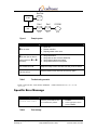
System Block Diagram
User-Supplied Peripherals
CCPU SCSI Card
Rear Panel
Terminator
Ultra Wide
SCSI-2
Interface
Disk
CD
DAT
Terminator
PCI-SCSI
CPU
CPCI
Interface
Figure 1
System block diagram
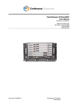
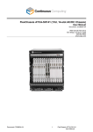
Photo
Figure 2
Continuous Computing Corp.
San Diego, CA
scsiUp
Page 7
scsiUp Installation and User’s Guide
File: 0-02355MN0-01.doc
Last saved: 3/16/01 10:53 AM
2 Unpacking, Installing, and Starting Up
Electrostatic Discharge (ESD)
!
Caution – scsiUp contains electronic components that are extremely sensitive to
static electricity. Ordinary amounts of static from clothing and the surrounding
environment may destroy components.
What to do
•
Use an antistatic mat.
•
Use an antistatic wrist or foot strap.
Storage
•
If the system is to be stored before unpacking, see Table 7 for environmental storage
specifications.
Unpack scsiUp
!
Caution – Always maintain an ESD-safe environment when handling scsiUp. It
contains many components that can be destroyed by ESD.
•
Inspect the shipping container for any in-transit damage and report it to the shipping
agent if necessary.
•
Carefully unpack scsiUp from its shipping container.
Power Down Your System
1.
2.
Ensure that your system’s OS has been shut down. In Solaris, do this using the halt
command.
Power down the system.
Install scsiUp
!
Caution – You cannot install an I/O card in the slot designated for a CPU card, or
vice-versa.
Continuous Computing Corp.
San Diego, CA
Page 8
scsiUp Installation and User’s Guide
File: 0-02355MN0-01.doc
Last saved: 3/16/01 10:53 AM
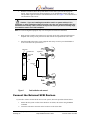
1.
Slide the card into its slot in the system chassis. As the card’s ejector latches engage the
chassis, apply forward pressure while pushing the ejector latch handles toward each other.
This procedure applies to both the front and transition cards. See Figure 3 for an illustration of
card installation and removal.
!
Caution – If you are installing the transition card in a system with an H.110
backplane or other backplane without J4 on the rear, then you must carefully align the
transition card visually. This is critical; bent pins will result if you do not visually align
the transition card in an H.110 backplane.
Note: J4 is used for alignment purposes only. It is not required for electrical connections.
2.
When properly installed, the connectors of each card will be fully engaged with the chassis’
midplane. The scsiUp’s front panel will sit flush with the front panels of the other cards.
3.
Install and tighten the captive screws supplied with scsiUp on each ejector latch handle to
secure each card to the system chassis.
Captive Screw
Latch Handle Cam
Alignment Pin
Ejector Latch
Handle
Closed
Open
Card
Card
Connectors
Open
Front
Figure 3
Side
Closed
Card installation and removal
Connect the External SCSI Devices
If you need to connect external SCSI devices to the system, follow the procedure defined below:
1.
2.
Ensure that the system’s OS has been shut down. In Solaris, this is done using the halt
command.
Locate the SCSI OUT connector on the last device in the SCSI chain.
Continuous Computing Corp.
San Diego, CA
Page 9
scsiUp Installation and User’s Guide
File: 0-02355MN0-01.doc
Last saved: 3/16/01 10:53 AM
3.
4.
5.
Remove the SCSI terminator from the SCSI OUT connector.
Connect the external SCSI device to the SCSI OUT connector.
Connect the SCSI terminator to the SCSI OUT connector on the last device in the external
SCSI device chain. Note that a SCSI chain can consist of no more than 15 devices and that
each device must have a unique SCSI ID.
Power On Your System
1.
2.
Power up and boot –r (from OpenBoot) or
drvconfig ; disks ; tapes (as root from Solaris).
SCSI devices will appear as:
/dev/dsk/c<c>t<t>d<d>s<s>
and
/dev/rdsk/c<c>t<t>d<d>s<s>
Where:
c is the controller number
t is the SCSI target
d is the LUN (almost always 0)
s is the disk slice
For example, the first disk on the first SCSI I/O card in the system should show up as:
/dev/dsk/clt0d0s[0-7]
Note: scsiUp does not require a driver. It uses the device driver built into Solaris.
SCSI IDs
The following are typical SCSI IDs used with most systems:
DISK: SCSI ID 0, 1, 2, or 3
DAT: SCSI ID 4 or 5
CDROM: SCSI ID 6
scsiUp: SCSI ID 7
However, you are free to select any SCSI IDs you wish.
SCSI Termination
scsiUp has active wide terminators on board. A terminator must be used at the end of the SCSI bus
(active terminators are strongly preferred for best operation).
Note: scsiUp supplies termination power. scsiUp will accept external termination power even if the
system is powered down.
Continuous Computing Corp.
San Diego, CA
Page 10
scsiUp Installation and User’s Guide
File: 0-02355MN0-01.doc
Last saved: 3/16/01 10:53 AM
To Change the Initiator SCSI ID (optional)
The default SCSI ID for the card is 7 unless modified through OpenBoot or through the operating
system.
Under OpenBoot, all SCSI controllers can be changed to the same ID.
At the ok prompt, use the following command:
setenv scsi-initiator-id <scsi-id>
SCSI ID Configuration
No two devices may have the same SCSI ID. By default, scsiUp uses SCSI ID 7. External devices are
normally configured through jumpers. Please refer to the respective external device manual for the
particulars of its jumper settings.
Continuous Computing Corp.
San Diego, CA
Page 11
scsiUp Installation and User’s Guide
File: 0-02355MN0-01.doc
Last saved: 3/16/01 10:53 AM
3 Troubleshooting
Troubleshooting Scenarios
In the event that scsiUp should fail in any way, use the following procedures to troubleshoot.
Note: The transition card contains only passive components and therefore is extremely unlikely to be
the cause of failure.
Before you begin
1.
2.
Halt the operating system.
From the ok prompt run the probe-scsi-all command:
•
Use probe-scsi-all -f if you just halted the operating system.
•
If you interrupted the boot sequence or executed a reset with
auto-boot? false, then use probe-scsi-all.
Outputs from probe-scsi-all command for system shown in Figure 4
!
"
Typical SCSI Card
Controller
Typical Secondary
Chain Disk Devices
/pci@1f,0/pci@1/pci@1/scsi@d
Target 0
Unit 0
Disk
IBM
DNES-309170Y
SA30
Target 1
Unit 0
Disk
IBM
DNES-309170Y
SA30
#
Typical Secondary
Chain CD Device
Target 6
Unit 0
Removable Read Only device
PLEXTOR CD-R
PX-W4220T1.01
$
CP1500 Onboard
Controller
/pci@1f,0/pci@1,1/scsi@2
%
Typical Primary Chain
Boot Disk Entry
Table 2
Continuous Computing Corp.
San Diego, CA
Target 0
Unit 0
Disk
IBM
DNES-309170Y
SA30
Outputs from probe-scsi-all command
Page 12
scsiUp Installation and User’s Guide
File: 0-02355MN0-01.doc
Last saved: 3/16/01 10:53 AM
Boot Disk
CP 1500
PCI
Disk 0
Disk 1
CD-ROM
ID 0
ID 1
ID 6
SCSI
Card
Figure 4
Example system
If…
Then…
! is not seen:
1. Power off.
2. Reseat controller.
3. Repeat probe-scsi-all.
! is seen (but no device
entries similar to " or #
are seen):
1.
2.
3.
4.
This continues to fail:
Swap the scsiUp’s front card with one that you know works.
If all else is fine:
Reseat transition card and front card and try again.
Table 3
Verify termination.
Verify devices are at correct SCSI IDs.
Verify that all cables are seated.
Verify that all devices have power.
Troubleshooting scenarios
Finally, if all looks fine, restart Solaris with boot -r and recheck devices in /dev/dsk or
/dev/rmt
Specific Error Message
Error Message
What it Means
invalid disk label
A disk is present that has not
been initialized by Solaris.
Table 4
Continuous Computing Corp.
San Diego, CA
What to Do
1. Under Solaris, run
format.
2. Select appropriate device
and use label.
Error message
Page 13
scsiUp Installation and User’s Guide
File: 0-02355MN0-01.doc
Last saved: 3/16/01 10:53 AM
Removing scsiUp
To remove scsiUp’s front card:
1.
2.
3.
4.
Halt the operating system.
Remove power (if desired).
Remove scsiUp’s front card.
If you are not replacing the card with a new one, use boot –r on your next boot to ensure
the new configuration is recognized.
Removing the Transition Card
To remove the transition card:
1.
2.
3.
4.
Halt the operating system.
Remove power (if desired).
Disconnect SCSI devices and remove the transition card.
If you are not replacing the card with a new one, use boot –r on your next boot to ensure
the new configuration is recognized.
Contact Technical Support
If you continue to experience problems with scsiUp, contact the Technical Support team at
Continuous Computing. See Section 5 for contact information.
Continuous Computing Corp.
San Diego, CA
Page 14
scsiUp Installation and User’s Guide
File: 0-02355MN0-01.doc
Last saved: 3/16/01 10:53 AM
4 Connector Usage, Pinout, and
Specifications
Connector Usage
Connector Usage
J1
PCI
J2
Not used/Not installed
J3
SCSI signals
J4
Mechanical alignment only
J5
Not used/Not installed
Table 5
Connector usage
P3
J5
J5
J4
J4
F4
J3
J3
F3
J2
P1
scsiUp
Figure 5
Continuous Computing Corp.
San Diego, CA
J1
Midplane
Transition Card
Connectors
Page 15
scsiUp Installation and User’s Guide
File: 0-02355MN0-01.doc
Last saved: 3/16/01 10:53 AM
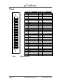
Pinout
1
35
34
68
Table 6
Continuous Computing Corp.
San Diego, CA
Pin
1
2
3
4
5
6
7
8
9
10
11
12
13
14
15
16
17
18
19
20
21
22
23
24
25
26
27
28
29
30
31
32
33
34
Signal
GND
GND
GND
GND
GND
GND
GND
GND
GND
GND
GND
GND
GND
GND
GND
GND
Termination Power
Termination Power
No Connect
GND
GND
GND
GND
GND
GND
GND
GND
GND
GND
GND
GND
GND
GND
GND
Pin
35
36
37
38
39
40
41
42
43
44
45
46
47
48
49
50
51
52
53
54
55
56
57
58
59
60
61
62
63
64
65
66
67
68
Signal
DB12
DB13
DB14
DB15
DBP1
DB0
DB1
DB2
DB3
DB4
DB5
DB6
DB7
DBP
GND
GND
Termination Power
Termination Power
No Connect
GND
ATN
GND
BSY
ACK
RST
MSG
SEL
C/D
REQ
I/O
DB8
DB9
DB10
DB11
SCSI connector pinout
Page 16
scsiUp Installation and User’s Guide
File: 0-02355MN0-01.doc
Last saved: 3/16/01 10:53 AM
Specifications
Functional
One Single-Ended Ultra-Wide SCSI-2 Bus
Capable of 40 MB/s
Software
Compatible with Solaris 2.5.1, Solaris 2.6, Solaris 7, and Solaris 8
Compatible with OpenBoot to support booting or CD-ROM installations
Connectors
Single 68 pin SCSI-2 connector on transition card
Electrical
7.5W at 5V power consumption
Mechanical
6U Single Slot CompactPCI Card (233.35mm x 160mm)
6U Single Slot CompactPCI Transition Card (233.35mm x 80mm)
Operating Mechanical and Environmental
Mechanical
Eurocard 6U, 1slot
160mm x 233.35 mm x 20 mm
Temperature -5°C to 55°C (Operating)
Humidity
5% to 90% relative humidity, noncondensing
Altitude
3000m
Storage/Transit Environmental
Temperature -40°C to 70°C
Humidity
10% to 95% relative humidity, noncondensing
Altitude
10000m
Safety Compliance
UL/cUL1950 3rd Edition Recognized Component
Electromagnetic Compatibility (EMC)
FCC Class A
Telco Compliance
Designed for Telcordia NEBS GR-63-CORE Level 3
Designed for Telcordia NEBS GR-1089-CORE Level 3
Marks
UL, cUL, CE
Table 7
Continuous Computing Corp.
San Diego, CA
SpecifIcations
Page 17
scsiUp Installation and User’s Guide
File: 0-02355MN0-01.doc
Last saved: 3/16/01 10:53 AM
5 Technical Support
Before contacting the Technical Support team at Continuous Computing, be sure you have read
Section 3, “Troubleshooting,” of this guide.
If you continue to experience problems with scsiUp, please contact the Technical Support team at
Continuous Computing by any of the methods listed below.
Note: Please be sure to include the serial numbers for each affected module, system and/or part. In
addition, we will need to know what version of Solaris (or other operating system) you are running, as
well as the patch level, and any other significant software packages that are installed.
Contacting Technical Support
To contact the Technical Support team at Continuous Computing, do one of the following:
•
•
•
Email us at [email protected]
Visit our support web site at http://support.ccpu.com
(This site features our automatic technical support system. Create a new user profile.
Then submit a new ticket at the “Welcome to SupportWizard” page. This process ensures
that our team delivers a timely solution to any technical problem you have.)
Call us at (858) 882-8911, 9:00 a.m. – 5:00 p.m. (PST)
Note: If you have a Gold or Platinum service contract, follow the contact instructions provided with
your contract.
Continuous Computing Corp.
San Diego, CA
Page 18
scsiUp Installation and User’s Guide
File: 0-02355MN0-01.doc
Last saved: 3/16/01 10:53 AM