1
Continuous Control Node (CCN)
for CompactPCI
Reference Manual
9380 Carroll Park Drive
San Diego, CA 92121-2256
858-882-8800
www.ccpu.com
Continuous Computing Corporation
Proprietary and Confidential
Page 1 of 34
CCN Reference Manual
CC00274-08.doc
Last saved: 10/25/2001 5:44 PM
© 2001 Continuous Computing Corporation. All rights reserved.
The information contained in this document is provided “as is” without any express representations of warranties. In addition,
Continuous Computing Corporation disclaims all implied representations and warranties, including any warranty of merchantability,
fitness for a particular purpose, or non-infringement of third party intellectual property rights.
This document contains proprietary information of Continuous Computing Corporation or under license from third parties. No part of
this document may be reproduced in any form or by any means or transferred to any third party without the prior written consent of
Continuous Computing Corporation.
Continuous Computing, the Continuous Computing logo, upSuite, upDisk, upBeat, upRules, upState, Continuous Control Node
(CCN), Continuous System Controller, CCPUnet, CCNtalk, Field Replaceable Microprocessor (FRµ), and Field Replaceable System
are trademarks or registered trademarks of the Continuous Computing Corporation or its affiliates. All other product names mentioned
herein are trademarks or registered trademarks of their respective owners. The products described in this document maybe protected
by U.S. patents, foreign patents, or pending applications. No part of this publication may be reproduced, stored in a retrieval system or
transmitted, in any form or by any means, photocopying, recording or otherwise, without prior written consent of Continuous
Computing Corporation. No patent liability is assumed with respect to the use of the information contained herein. While every
precaution has been taken in the preparation of this publication, Continuous Computing Corporation assumes no responsibility for
errors or omissions. This publication and features described herein are subject to change without notice .
Sun, the Sun logo, SPARCengine, Solaris, and OpenBoot are trademarks or registered trademarks of Sun Microsystems Inc. in the
United States and other countries. All SPARC trademarks are used under license and are trademarks or registered trademarks of
SPARC International, Inc. in the United States and other countries. Products bearing SPARC trademarks are based upon an
architecture developed by Sun Microsystems, Inc.
CompactPCI is a registered trademark of PICMG.
The information contained in this document is not designed or intended for use in human life support systems, on-line control of
aircraft, aircraft navigation or aircraft communications; or in the design, construction, operation or maintenance of any nuclear facility.
Continuous Computing Corporation disclaim s any express or implied warranty of fitness for such uses.
Continuous Computing Corporation
Proprietary and Confidential
Page 2 of 34
CCN Reference Manual
CC00274-08.doc
Last saved: 10/25/2001 5:44 PM
Table of Contents
1
INTRODUCTION........................................................................................................... 5
U SING THIS M ANUAL............................................................................................................................................. 5
GLOSSARY ............................................................................................................................................................... 5
DESCRIPTION ........................................................................................................................................................... 5
BLOCK DIAGRAM ................................................................................................................................................... 6
TYPOGRAPHIC CONVENTIONS .............................................................................................................................. 7
2
INTERFACES................................................................................................................ 8
FRONT PANEL.......................................................................................................................................................... 8
REAR PANEL I/O CONNECTIONS........................................................................................................................ 10
3
COMMAND LINE INTERFACE (CLI)............................................................................ 12
CLI OPERATION.................................................................................................................................................... 12
CLI PROMPT.......................................................................................................................................................... 12
CLI SYNTAX ......................................................................................................................................................... 12
CLI COMMANDS................................................................................................................................................... 12
CONNECT .................................................................................................................................................... 12
DEFCONFIG................................................................................................................................................ 13
HELP............................................................................................................................................................. 13
LOGOUT....................................................................................................................................................... 14
PROBE .......................................................................................................................................................... 14
RSH ............................................................................................................................................................... 14
TIME ............................................................................................................................................................. 15
FIRMWARE DOWNLOAD....................................................................................................................................... 15
4
NODE COMMANDS ..................................................................................................... 17
ALARMS........................................................................................................................................................ 17
APP ............................................................................................................................................................... 17
CPURESET ................................................................................................................................................... 17
FAULTS ........................................................................................................................................................ 17
FORECEOFF................................................................................................................................................ 18
INFO ............................................................................................................................................................. 18
INITMODE.................................................................................................................................................... 19
IOSTAT.......................................................................................................................................................... 19
LEDTEST...................................................................................................................................................... 19
MASK ............................................................................................................................................................ 20
MONITOR..................................................................................................................................................... 20
NODENAME................................................................................................................................................. 20
OFF............................................................................................................................................................... 21
ON................................................................................................................................................................. 21
PASSWD........................................................................................................................................................ 21
PICS .............................................................................................................................................................. 21
RESET ........................................................................................................................................................... 21
RLYTEST....................................................................................................................................................... 22
SER2MODE.................................................................................................................................................. 22
SERIAL .......................................................................................................................................................... 22
SMHALT........................................................................................................................................................ 23
SMRESET ...................................................................................................................................................... 23
STATUS......................................................................................................................................................... 23
SUBMOD...................................................................................................................................................... 23
VOLTAGES................................................................................................................................................... 24
WDOGS......................................................................................................................................................... 24
5
ALARM GENERATION ................................................................................................ 25
A LARM STATES..................................................................................................................................................... 25
Continuous Computing Corporation
Proprietary and Confidential
Page 3 of 34
CCN Reference Manual
CC00274-08.doc
Last saved: 10/25/2001 5:44 PM
FAULTS................................................................................................................................................................... 25
FAULTMASK REGISTER................................................................................................................................... 26
GENERATING A LARMS FROM FAULTS.............................................................................................................. 28
6
TROUBLESHOOTING................................................................................................. 30
SERIAL CLI CONNECTIONS................................................................................................................................. 30
CONTACT TECHNICAL SUPPORT ......................................................................................................................... 31
7
PINOUTS AND SPECIFICATIONS .............................................................................. 32
SERIAL DCE (DB-9) ............................................................................................................................................ 32
CCPUNET (RJ-45)................................................................................................................................................ 32
SPECIFICATIONS (PRELIMINARY/EXPECTED)................................................................................................... 33
8
TECHNICAL SUPPORT............................................................................................... 34
CONTACTING TECHNICAL SUPPORT .................................................................................................................. 34
TABLE OF FIGURES
FIGURE 1 CCN BLOCK DIAGRAM........................................................................................................................ 6
FIGURE 2 F RONT PANEL INTERFACE ................................................................................................................... 8
FIGURE 3 CCN TRANSITION MODULE , REAR PANEL INTERFACE.................................................................. 10
TABLE OF TABLES
TABLE 1 TYPOGRAPHIC CONVENTIONS.............................................................................................................. 7
TABLE 2 APP LED STATES ................................................................................................................................. 9
TABLE 3 ON LED STATES................................................................................................................................... 9
TABLE 4 OFF LED STATES ................................................................................................................................. 9
TABLE 5 CONNECT ACTIONS AND SEQUENCES................................................................................................ 13
TABLE 6 A PPLICATION FAULT BITS DETECTED BY CCN-C CPI .................................................................. 18
TABLE 7 A LARM STATES.................................................................................................................................... 25
TABLE 8 VOLTAGES MONITORED BY CCN-C CPI........................................................................................... 26
TABLE 9 PRESENCE BITS DETECTED BY CCN- C CPI....................................................................................... 27
TABLE 10 M ISCELLANEOUS INPUT FAULT BITS DETECTED BY CCN-C CPI ................................................ 27
TABLE 11 POWER SUPPLY FAULT BITS DETECTED BY CCN-C CPI ............................................................... 28
TABLE 12 A PPLICATION FAULT BIT S DETECTED BY CCN-C CPI .................................................................. 28
TABLE 13 CCPUNET BUS FAULT BITS DETECTED BY CCN- CCPI ................................................................ 28
TABLE 14 SERIAL DCE (DB-9) PINOUT .......................................................................................................... 32
TABLE 15 CCPUNET (RJ-45) PINOUT .............................................................................................................. 32
TABLE 16 SPECIFICATIONS ................................................................................................................................ 33
Continuous Computing Corporation
Proprietary and Confidential
Page 4 of 34
CCN Reference Manual
CC00274-08.doc
Last saved: 10/25/2001 5:44 PM
1 Introduction
Welcome to the Continuous Control Node (CCN) Reference Manual. This document provides an
overview of how the Continuous Control Node (CCN) interacts with the user and with other elements
in a CompactPCI system.
This manual contains the following information related to the CCN module:
•
Description
•
How the CCN works
•
Features and Benefits
•
Front panel interface
•
Rear panel I/O connections
•
Command Line Interface
•
Pinouts
•
Specifications
•
Troubleshooting
Using This Manual
The CCN Reference Manual is written for computer technicians and hardware and software
engineers. It is assumed that the user of the CCN has the following background:
•
Familiarity with the handling of ESD-sensitive electronic equipment
•
Familiarity with the Solaris operating system
Glossary
Compute Node is a CPU, a Continuous Control Node (CCN), and peripherals, such as I/O cards and
disk drives, which are connected to the CPU.
Description
The Continuous Control Node (CCN):
•
Monitors and controls a compute node in a CompactPCI system.
•
Provides the administrator with the ability to turn the system on or off, monitor power
and temperature, and access the CPU console remotely.
•
Can set off alarms by using its relay.
Continuous Computing Corporation
Proprietary and Confidential
Page 5 of 34
CCN Reference Manual
CC00274-08.doc
Last saved: 10/25/2001 5:44 PM
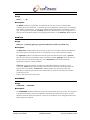
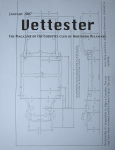
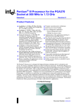
Block Diagram
Continuous Control Node (CCN)
Midplane
CompactPCI Voltages
Terminal
or
Workstation
Disk Presence Indicator
Serial 3/
Front
Power Enable/Disable
Power OK Signal
Standby Power
Serial 2
TTYB
Serial 1
TTYA
Serial 0
CPU
Microprocessor
To office alarms
CAN B
To other CCNs and
Compute Nodes
CCPUnet
Figure 1
Power Supply
Temp
Relay
CAN A
Dual Disk Carrier
CCN block diagram
Continuous Computing Corporation
Proprietary and Confidential
Page 6 of 34
CCN Reference Manual
CC00274-08.doc
Last saved: 10/25/2001 5:44 PM
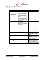
Typographic Conventions
A summary of the typographic conventions used in this manual is listed in Table 1 below.
Typeface/Symbol
AaBbCc123
AaBbCc123
<AaBbCc123>
[AaBbCc123]
{<a> <b>}
AaBbCc123
Example
The names of commands,
files and directories; onscreen computer output
What you type, contrasted
with on-screen computer
output
Command-line placeholder or
token to be replaced with a
real name or value (do not
type brackets)
Optional argument (do not
type brackets)
Required argument (do not
type brackets)
Book titles, new words or
terms, or words to be
emphasized
Edit your .login file.
At the ok prompt….
ABC
Acronyms
Ctrl
Keystroke press
Caution
!
Table 1
Meaning
To turn the unit on, type on
at the ccpu> prompt. i.e.,
ccpu>:on
To delete a file, type rm
<filename>.
[help]
dir [<filename>]
{<na> <cmd>}
grade {a, b, c, d, f}
• This manual is used in
conjunction with the
SPARCengine CP1500
User’s Manual.
• You must be grounded
to avoid ESD damage to
the equipment.
Locate the On / Off toggle
switch on the CCN front
panel.
Send a break using Ctrl-].
(Note: Hold down the Ctrl
key and then press ]. Do not
include the hyphen).
Failure to heed the
instructions that follow the
Caution symbol may result
in damage to the equipment.
Typographic conventions
Continuous Computing Corporation
Proprietary and Confidential
Page 7 of 34
CCN Reference Manual
CC00274-08.doc
Last saved: 10/25/2001 5:44 PM
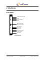
2 Interfaces
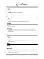
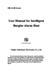
Front Panel
APP
Application (user defined) LED
ON
On LED
OFF
On / Off Toggle Switch
Off LED
CONS
DB9 Serial Female DCE
Craft Console Connection
Critical Fault LED
Major Fault LED
Minor Fault LED
CR
MJ
MN
RST
Reset Switch (Recessed)
FLT
Controller Fault LED
SWP
Swap OK LED
Figure 2
Front panel interface
Continuous Computing Corporation
Proprietary and Confidential
Page 8 of 34
CCN Reference Manual
CC00274-08.doc
Last saved: 10/25/2001 5:44 PM
APP (APPLICATION) LED
LED state
ON
BLINKING
OFF
Table 2
Information conveyed
Solaris is booted and CCPUnet daemon (CCNd) is
communicating with the CCN
Single blink indicates Sun is in the process or
booting or halting. Double-blink indicates CCN
lost contact with CCNd.
The CPU is off, has not begun booting, or has
finished halting. If this LED is off, then the CCN
knows the CPU is in a state where power removal
will not harm the boot disk/operating system
image.
APP LED states
ON LED
LED state
ON
OFF
Table 3
Information conveyed
The CCN is requesting that the power supply
provide system voltages to the CPU, I/O cards, and
disks.
The CCN is requesting that the power supply turn
off.
ON LED states
ON/OFF TOGGLE SWITCH
Press towards ON for one second to instruct the CCN to turn the system on. Hold towards DOWN for
one second to begin a soft shutdown. If the CPU is already halted or must be shutdown ungracefully
for some reason, hold the switch towards DOWN for 5 seconds.
OFF LED
LED state
ON
BLINKING
OFF
Table 4
Information conveyed
The power supply is off.
The CCN has requested that the CPU shut down
gracefully and is awaiting confirmation of the
shutdown.
The power supply is on.
OFF LED states
CONS-DB-9 DCE CRAFT CONSOLE CONNECTION
This DB-9 is used for Command Line Interface interaction. The default settings are 38400 baud, 8
bits, no parity, 1 stop bit. This port is DCE, so a straight-through DB-9 cable may be used to connect
this port to a standard PC-compatible DB-9 serial port.
CR – CRITICAL ALARM LED
The CR – Critical Alarm LED lights when this CCN has a critical alarm active or latched.
MJ – MAJOR ALARM LED
The MJ – Major Alarm LED lights when this CCN has a major alarm active or latched.
Continuous Computing Corporation
Proprietary and Confidential
Page 9 of 34
CCN Reference Manual
CC00274-08.doc
Last saved: 10/25/2001 5:44 PM
MN – MINOR ALARM LED
The MN – Minor Alarm LED lights when this CCN has a minor alarm active or latched.
RST – RESET SWITCH
The RST – Reset Switch will reset the Control Node only. Doing so will not affect the CPU module
or power supplies.
FLT – CONTROLLER FAULT LED
The FLT – Controller Fault LED lights when the CCN detects some form of internal or CCN-related
fault.
SWP – SWAP LED
The SWP – Swap LED is currently not used. The CCN may be hot-swapped at any time.
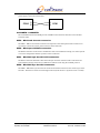
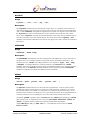
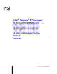
PWRB
AUX POWER INPUT B
PWRA
Rear Panel I/O Connections
AUX POWER INPUT A
CCPUNETB
RJ45 CCPUNETB
RJ45 CCPUNETA
DB9 CRAFT CONSOLE CONNECTION
(DUPLICATE OF DB9 ON FRONT PANEL)
SER1
DB9 SPARE CCNtalk CONNECTION
DB9 SERIAL FEMALE DCE CCN DAEMON / ttyb SUN CONNECTION
SER0
SER2
SER3
CCPUNETA
DB9 SERIAL FEMALE DCE ttya SUN CONSOLE CONNECTION
Figure 3
CCN transition module, rear panel interface
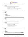
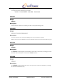
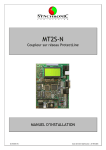
PWRA / PWRB – AUX POWER INPUT A/B
The PWRA / PWRB – Aux Power Input A/B inputs are used to input power to or receive power from
a CCN. If a CCN is controlling two power supplies, these connectors should not be used because the
CCN is receiving power from each supply. In a duplex system where each node has a single supply,
Continuous Computing Corporation
Proprietary and Confidential
Page 10 of 34
CCN Reference Manual
CC00274-08.doc
Last saved: 10/25/2001 5:44 PM
the A and B inputs on the two CCNs can be cross-connected to provide power to a CCN even if its
power supply is removed or has a fault.
CCN0 A
B
A
CCN1
B
CCPUNETA / CCPUNETB
The CCPUNETA and CCPUNETB provide redundant interconnections between CCNs and other
CCPUnet nodes.
SER3 – DB-9 Craft Console connection
The SER3 – DB-9 Craft Console connection is a duplicate of the front-panel CONS connector. Do
not connect to the front and rear panel connectors at the same time.
SER2 – DB-9 spare CCNtalk connection
The SER2 connection can be used to communicate with a CCNd daemon running on a remote system
or it can be configured as another ttya Sun Console connection.
SER1 – DB-9 DCE ttyb Sun CPU CPU connection
The SER1 connection should be connected to the ttyb connector of the Sun CPU. This allows the
CCNd daemon running on the Sun to communicate with the CCN using the CCNtalk protocol.
SER0 – DB-9 DCE ttya Sun CPU connection
The SER0 – DB-9 DCE ttya Sun Console connection should be connected to the console (ttya) of the
Sun CPU. This allows console access through CCPUnet (from the CLI or by telnet access to CCNd).
Continuous Computing Corporation
Proprietary and Confidential
Page 11 of 34
CCN Reference Manual
CC00274-08.doc
Last saved: 10/25/2001 5:44 PM
3 Command Line Interface (CLI)
The CCN command line interface (CLI) allows operators and maintenance personnel to query system
status and modify the system state using a simple RS232 terminal. A CCN can thus be used as a
management interface to an entire system without any other processing elements.
CLI Operation
The CLI accepts input one line at a time. Backspace (ASCII 0x08) or Delete (ASCII 0x7f) may be
used to erase characters, Control-U may be used to erase an entire line, and Carriage-Return (ASCII
0x0d) or Newline (ASCII 0x0a) will end a line of input. Any lines beginning with ‘#’ will be ignored
as comments.
CLI Prompt
The CLI prompt looks like this:
nodename (na) ccncli>
where nodename is the name of the node into which the craft terminal is plugged and na is the node
address.
CLI Syntax
A CLI command line consists of a command followed by optional arguments.
Note: Multiple whitespace is treated as a single space.
CLI Commands
The following sections describe the command formats for the CLI commands. Note that all
commands are case-sensitive and that typically lowercase characters are used.
CONNECT
Usage
connect [[<na>][.<sub>]]
Description
Connecting to a node establishes a serial connection from the CLI terminal to a serial port on a node
(generally used for the CPU ttya console port). If no node address argument <na> is specified, then
the current node on which the CLI is running is the default. Also, if no subnode argument <sub> is
provided, then the default subnode 0 (i.e. SER0) is used. Note that the period “.” is required if the
subnode argument <sub> is specified. connect will check a subnode to ensure it is configured
as serial packetizer (SERPKT) prior to forming the connection. The spare serial connection SER2 is
normally set to its default state as a CCNtalk connection, but can be configured as a SERPKT
connection (see the ser2mode node command for further details on SER2 configuration).
Once connected, all characters typed on the CLI will be sent to the serial port, and all characters
received on the serial port will be displayed on the CLI terminal. The only exception to this is when
Continuous Computing Corporation
Proprietary and Confidential
Page 12 of 34
CCN Reference Manual
CC00274-08.doc
Last saved: 10/25/2001 5:44 PM
the user types the escape character (Control-]). After typing the escape character, the user may
use telnet-like (command line) or tip-like (single-character) sequences for certain actions as show in
Table 5.
If a single -character command is sent within one second of the escape character, then no prompt will
be printed; otherwise, a connect> prompt will be printed to notify the user that the CCN is waiting
for an escape command. Single -character commands are still accepted even if a prompt is printed.
Unless the “.” or exit command is used, the CCN will return to connected mode after the command
is executed.
Action
Send serial BREAK
Send escape char
Show help info
Close connection, return
to CLI
Table 5
Single char.
#
^]
?
.
Command line
send break
send escape
help
exit
Connect actions and sequences
Example
switchmon(03) ccncli> connect 2
Connecting to console on CCN 02. Escape char is Ctrl-]
dns1 console login: root
Last login: Fri Jan 29 20:52:08 on console
Feb 2 18:20:07 dns1 login: ROOT LOGIN /dev/console
Sun Microsystems Inc. SunOS 5.6 Generic August 1997
#
<User hits ctrl-]>
Connected to console on 02.
connect> exit
Disconnecting from console on CCN 02.
switchmon(03) ccncli>
DEFCONFIG
Usage
defconfig
Description
Reprograms the EEPROM to its generic factory default configuration. This is a hidden command.
Care must be taken when using this command since it will erase all of the configuration variables that
are stored in EEPROM.
HELP
Usage
help
Continuous Computing Corporation
Proprietary and Confidential
Page 13 of 34
CCN Reference Manual
CC00274-08.doc
Last saved: 10/25/2001 5:44 PM
Description
Prints a list of all available commands.
Example
An example of the use of this command will produce a display as follows.
switchmon (03) ccncli> help
***** CLI Commands:
connect <na> connect to serial console of node na
rsh <na> <cmd> send node na command cmd
probe [na] probe node na (or all nodes)
LOGOUT
Usage
logout
Description
Logs out of the CLI if password was enabled by the passwd command. If the password is not set,
then logout has no effect.
PROBE
Usage
probe
Description
probe listens for heartbeat packets from other nodes on the CCPUnet. After listening for two
seconds, it queries status from all detected nodes and displays that status.
Example
An example of the use of this command will produce a display as follows.
switchmon(03) ccncli> probe
Listening: 02 03
NodeName(NodeAddr) NodeSt AlarmSt
testbox2 (02) ON-VULN No_Alarms
switchmon(03) OFF Major
switchmon(03) ccncli>
RSH
Usage
rsh
Description
Requests a remote node (specified by node) run a command and return the output. command may
consist of any command acceptable to the remote CCN.
Continuous Computing Corporation
Proprietary and Confidential
Page 14 of 34
CCN Reference Manual
CC00274-08.doc
Last saved: 10/25/2001 5:44 PM
Example
An example of the use of this command will produce a display as follows.
switchmon(03) ccncli> rsh 2 help
connect <na> connect to serial console of node na
rsh <na> <cmd> send node na command cmd
probe [na] probe node na (or all nodes)
rsh <naddr> <command>
...
switchmon(03) ccncli>
TIME
Usage
time
Description
Shows the number of seconds that the CCN has been running since the last reset. This is a hidden
command.
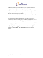
Firmware Download
Usage
@
Description
The CCN has flash-upgradeable firmware. To upgrade the image, you must connect to the CCN CLI
from a machine that is capable of sending a large text file to the CLI as though it were being typed in.
Follow the steps below and refer to the following paragraphs for more specific details pertaining to
downloading on a Windows or a Linux/Unix machine.
1.
2.
3.
4.
Connect to the CCN CLI (SER3 on the back or CONS on the front).
At the ccncli> prompt, send the @ command.
The CCN will respond with Send Continuous Computing CCN
software update file now .
Send the firmware image file as a text file (refer to the instructions below for your
machine type). Once it is received completely, the CCN will reprogram itself and
reset.
Each line of the file is check-summed, and the entire file also has a checksum. If any
errors are detected, the CCN will abort the download and discard any additional lines
sent.
If any errors do occur during the download, follow this sequence:
a) Wait for your terminal program to finish sending the file.
b) When the file is sent, hit carriage return, followed by capital X.
c) Hit the carriage return again.
This instructs the download routine in the CCN to return control to the CLI.
Continuous Computing Corporation
Proprietary and Confidential
Page 15 of 34
CCN Reference Manual
CC00274-08.doc
Last saved: 10/25/2001 5:44 PM
Windows machine:
Use Hyperterm to connect to a CCN console. Make sure the serial port settings on the computer
match that of the CCN console (default settings are: 38400, 8N1, and, no flow control). At the CLI
prompt (ccncli>), enter @. The CCN will prompt the user to send the image file. Do this by
going to Transfer at the Hyperterm menu bar. Select Send Text File which will display
.txt files in the default Hyperterm directory. Then select All files (*.*) so that the “.i”
image file will be visible. You will also have to change directories to where the image file is located
on your computer. Once the desired image file has been located, double-click on it (or single click the
desired file to select it and then press the Open button).
Note: On a Windows NT or 2000 system, the file transfer is very slow even if the serial port settings
are correct. This is a known problem with Windows NT/2000.
Linux/Unix Machine:
This method requires two terminal windows to be opened, one to connect to the CCN console
(“console window”), the other to type the command to send the file (“command window”). From the
console window, connect to the CCN using the cu (Unix and Linux ) or tip (Unix only)
commands. Alternatively, a serial communications program (such as minicom on Linux
machines) can be used to connect to the console. Make sure the serial port settings match the CCN
console settings (for example, the full cu command on a Linux machine could be cu –s 38400
–l /dev/ttyS0 where it is assumed the CCN console is connected to the ttyS0 port on the
computer). Type the @ command; then, from the command window, type cat image_file.i
> /dev/ttyS0 where image_file.i should be the full name of the new image file. Make
sure you have read/write access to the serial port ttyS0 (or whichever port is being used). This can be
achieved by the command chmod 666 /dev/ttyS0, which will set the permissions
accordingly.
Continuous Computing Corporation
Proprietary and Confidential
Page 16 of 34
CCN Reference Manual
CC00274-08.doc
Last saved: 10/25/2001 5:44 PM
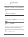
4 Node Commands
Node commands are sent across the network to other nodes. Node commands instruct a node to
perform a particular function. Node commands can also be executed on the local node (that is, it is not
necessary to use rsh <na> to execute a command on the local node).
ALARMS
Usage
alarms
Description
Reports the current system status including node name, node address, CCN node state, and alarm
state. This command is the same as the status command.
APP
Usage
app
Description
The app command allows the CLI user to view any application-requested faults, along with the
application-supplied fault message. See the appmsg command in /opt/CCPUclnt/bin or the
API documentation to send application faults.
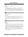
CPURESET
Usage
cpureset [0,1] [assert,deassert]
cpureset [help]
Description
Asserts or deasserts a software reset of the specified Sun CPU where 0 indicates the left CPU and 1
indicates the right CPU when viewed from the front in a duplex CompactPCI system. If no argument
is provided, then displays the reset status of both Sun CPUs. If a CPU reset has been asserted, then
the reset status indicates whether the reset was asserted by hardware, software, or both.
FAULTS
Usage
faults [<#>,masked,reset,all,help]
Continuous Computing Corporation
Proprietary and Confidential
Page 17 of 34
CCN Reference Manual
CC00274-08.doc
Last saved: 10/25/2001 5:44 PM
Description
Reports on system faults. With no argument, displays all of the active or latched faults. With a
numeric (decimal 0 to 31) argument, displays the current fault status of that particular fault number.
With the masked argument, displays all of the faults that are currently masked. With the reset
argument, resets all the faults. With the all argument, displays all the valid faults for the connected
CCN and their current fault status.
Application faults
The application running on the host can request that faults be asserted or cleared through the CCNtalk
interface. Setting these faults triggers the generation of critical, major, or minor alarms.
Each CCN maintains a watchdog timer with a daemon (CCNnc) running on the Solaris host. This
timer will assert the APPDOG fault if it expires. This fault, when asserted, triggers the generation of a
critical alarm.
Table 6 below lists the application fault bits detected by the CCN-cCPI.
Bit #
Name
Description
24
CCNALM
CCN has internal fault
25
26
27
28
APPMN
APPMJ
APPCR
APPDOG
Application requested minor alarm
Application requested major alarm
Application requested critical alarm
CCN Host (ccnnc) watchdog timed out
Table 6
Application Fault Bits Detected By CCN-cCPI
FORECEOFF
Usage
forceoff
Description
Forces the power to the Sun CPU off immediately. Whenever possible, the off command should be
used instead of forceoff to prevent data loss or corruption by inducing a graceful shutdown. If
the forceoff command is used, the user should halt the Solaris operating system on the Sun CPU
and wait for the ok prompt prior to using the forceoff command.
INFO
Usage
info
Description
The info command displays information about the target node such as hardware part number,
hardware serial number, hardware revision, software part number, software revision, and node type.
Also, the time up in seconds for the CCN since the last reset is also show in hexadecimal format.
Continuous Computing Corporation
Proprietary and Confidential
Page 18 of 34
CCN Reference Manual
CC00274-08.doc
Last saved: 10/25/2001 5:44 PM
INITMODE
Usage
initmode [on,off,check,help]
Description
Sets the CCN state upon power up or reset. If no argument is provided, then displays the current
setting for initmode. When the on argument is specified, the CCN attempts to turn on
immediately after power up or reset. When the off argument is specified, the CCN stays in the OFF
state. The default configuration is check where the CCN checks the power supplies and if power is
available, turns on, otherwise it stays off. CCPU recommends using the check initmode setting and
discourages the use of the off initmode setting which can result in a data loss or corruption.
IOSTAT
Usage
iostat {can,ser,ct}
Description
The command iostat checks and displays the input/output statistics for the selected
communication port buffers. If the argument can is specified, then the statistics for the CCPUnet
CAN bus are displayed. If the argument ser is specified, then the statistics for the four serial ports
are displayed. If ct is specified, then the statistics for CCNtalk port are displayed (number of
packets sent to or received from CCNd). iostat does require an argument.
LEDTEST
Usage
ledtest [[-]<#>,[-]all]
Description
The ledtest command tests any or all of the front panel LEDs by turning on the specified LEDs.
Likewise, specified LEDs can be turned off if preceded by the minus sign (–). Individual LEDs can
be specified by a single digit number where the top-most LED (i.e. APP LED) on the CompactPCI
CCN front panel is LED numb er 0 and sequentially increasing going downwards to the bottom-most
LED (i.e. SWP LED) which is LED number 7. Alternatively, the individual LEDs can be specified
by their abbreviated name (i.e. app, on, off, cr, mj, mn, flt, swp). All of the LEDs can be
selected by the argument all. If no argument is provided, then the ledtest status byte is
displayed where a non-zero value indicates that at least one LED is being driven. Because the
ledtest command works separately from and overrides the INHLED and FORCELED byte
variables, the user must be sure to turn all the LEDs off when finished testing. This can be done using
the command ledtest –all.
Continuous Computing Corporation
Proprietary and Confidential
Page 19 of 34
CCN Reference Manual
CC00274-08.doc
Last saved: 10/25/2001 5:44 PM
MASK
Usage
mask [[-]<#>]
Description
The mask command is used to mask out faults that the user does not want considered when
evaluating the current alarm state. A particular fault can be masked by specifying the corresponding
fault number as the argument. A fault can be unmasked if the fault number is preceded by a minus
sign. If no argument is specified, then mask will list all of the faults that are currently masked. For
a listing of all of the faults and their corresponding fault numbers, use the faults all command.
MONITOR
Usage
monitor [ignore|pwrcyc|cpures|smreset|falm-no|falm-nc]
Description
The monitor command allows the user to specify the action to be taken when the miscellaneous
dry contact inputs to the CCN are closed; if no argument is given, it shows the current setting.
The ignore argument is the default and basically ignores the miscellaneous inputs. cpures
resets the CPU when the miscellaneous inputs are closed (if cabled). pwrcyc cycles the power to
the CPU when the miscellaneous inputs are closed. smreset asserts SM reset when the
miscellaneous inputs are closed (if cabled).
falm-no generates a normally open fan alarm when the miscellaneous inputs are closed.
Conversely, falm-nc generates a normally closed fan alarm when the miscellaneous inputs are
opened. With no arguments, the monitor command displays the status of the inputs.The
miscellaneous inputs are pins 4 and 5 of the CCPUnet RJ -45 connector which share the common
ground on pin 6. See
Table 15 and Section 5 for more details.
NODENAME
Usage
nodename [<newname>]
Description
The nodename command renames the node to the user-specified name, if provided. If no argument
is specified, then displays the current nodename. Ordinarily, the nodename is set by the CCNd to
match the hostname of the associated CPU. However, the nodename can be changed from the CLI if
desired using this command.
Continuous Computing Corporation
Proprietary and Confidential
Page 20 of 34
CCN Reference Manual
CC00274-08.doc
Last saved: 10/25/2001 5:44 PM
OFF
Usage
off
Description
The off command requests a graceful shutdown.
ON
Usage
on
Description
The on command requests power to the node and begins the boot process.
PASSWD
Usage
passwd [<newpwd>]
Description
The passwd command sets the CLI password to that specified by the user. If no argument is
provided, then shows the current CLI password. To disable the CLI password, use the command
passwd none.
PICS
Usage
pics
Description
The pics command displays the power supply voltage data directly from the Microchip PIC16C72
on the power supplies.
RESET
Usage
reset
Description
The CCN has a “hidden” reset command to perform a software reset of the CCN. This command
has essentially the same effect as hitting the front-panel reset switch: all statistics are reset, faults and
alarms are cleared, etc. This command is not displayed in the help list so that people in the field will
not be tempted to use it indiscreetly.
Continuous Computing Corporation
Proprietary and Confidential
Page 21 of 34
CCN Reference Manual
CC00274-08.doc
Last saved: 10/25/2001 5:44 PM
RLYTEST
Usage
rlytest [[-]all,[-]cr,[-]mj,[-]mn]
Description
The rlytest command turns the specified dry contact relays “on” (normally closed contacts are
opened and normally open contacts are closed), or if the minus sign is used, turns the specified relays
“off”. Unlike ledtest, only alphabetic arguments are accepted. If no argument is provided, then
the rlytest byte status is returned which, if not zero, indicates that at least one relay is being
driven. Since rlytest overrides the normal functionality of the relays, the user should be sure to
clear the rlytest byte to zero when finished testing. This can be done with the rlytest –all
command. Note that the CompactPCI CCN only has one physical relay that is used for all of the three
alarm states.
SER2MODE
Usage
ser2mode [<mode>,help ]
Description
The ser2mode command allows run-time configuration of the SER2 port as a ttya connection to a
Sun processor or as a CCNtalk connection to the CCNd, which is the default configuration. The
following values for <mode> will configure SER2 as a ttya connection: ttya, sun, warp,
or serpkt. To configure SER2 as a CCNtalk connection, use ccntalk for the <mode>
argument. Note that a CCNtalk connection usually uses 38400 baud while a ttya connection typically
uses 9600 baud, so the serial command should be used in conjunction with the ser2mode
command to completely reconfigure the SER2 port to the desired state.
SERIAL
Usage
serial [<port> <param> <val> [<param> <val> …]]
Description
The serial command checks or sets the CCN serial port parameters. With no options, lists the
communication settings for all of the CCN serial ports. With arguments, configures a given port to
the specified settings. Port numbers can range from 0 to 3 where 0 is the Sun console ttya, 1 is the
Sun ttyb (used by CCNd as a CCNtalk port), 2 is a spare serial port which can be configured either as
a Sun ttya connection or as a CCNtalk port, and 3 is the craft console port that runs the CLI.
Acceptable <param> argument values are baud (baud rate), cfmt (character format), and flow
(flow control mode). Acceptable baud rate values are 1200, 2400, 4800, 9600, 19200, and
38400. Acceptable character formats can be formed from the following template:
{7,8}{n,N,e ,E,o,O}{1 ,2} (e.g. 8N1, 7e2, etc.). Acceptable flow control values are none,
hard, and soft.
Continuous Computing Corporation
Proprietary and Confidential
Page 22 of 34
CCN Reference Manual
CC00274-08.doc
Last saved: 10/25/2001 5:44 PM
Example
An example use of this command is given below:
serial 2 baud 38400 cfmt 8N1 flow hard.
SMHALT
Usage
smhalt
Description
Sends an OS halt command via CCNtalk port SER1 to the System Manager CPU.
SMRESET
Usage
smreset [assert|deassert]
Description
Asserts or deasserts reset to the System Manager CPU. A special cable is required.
Note: If monitor mode is SMRESET, then this command is OR'ed with the hardware SM reset signal.
STATUS
Usage
status
Description
The status command displays a brief summary of the node’s current status, including power and
alarm state. This command is the same as the alarm command.
SUBMOD
Usage
submod
Description
The submod command displays the current state and presence of the CCN submodules, including
the removable submodules, if any.
Continuous Computing Corporation
Proprietary and Confidential
Page 23 of 34
CCN Reference Manual
CC00274-08.doc
Last saved: 10/25/2001 5:44 PM
VOLTAGES
Usage
voltages [reset ]
Description
The voltages command will list all sampled voltages and temperatures along with the minimum
and maximum values since the last voltages reset command which clears all of the stored
min/max values. Also, the allowable upper and lower limits for each sampled voltage or temperature
are displayed. TEMP0 is the temperature within the chassis, ALM12A and ALM12B are the CCN
power feeds (ALM12B is only present in multi-node systems), TEMP1 is an extra sensor that is
typically not connected, and the remaining voltages are the CompactPCI midplane voltages.
WDOGS
Usage
wdogs
Description
The wdogs command displays the internal watchdog counters.
Continuous Computing Corporation
Proprietary and Confidential
Page 24 of 34
CCN Reference Manual
CC00274-08.doc
Last saved: 10/25/2001 5:44 PM
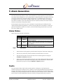
5 Alarm Generation
The CCN continuously monitors various critical parameters of system operation to ensure that they
stay within expected bounds for correct system operation. When parameters exceed preset values, the
CCN enters an alarm state. Information about the alarm state is available through several sources,
including front panel Critical, Major, and Minor LEDs, a dry contact relay output, CLI commands,
and a GUI via CCPUnet. This section details how the user interfaces with the CCN alarm code and
how the CCN monitors and responds to faults.
For the purposes of this discussion, a fault is the failure of a particular piece of hardware to stay
within expected operational parameters. An alarm is the state that the CCN assumes as a result of a
particular combination of faults. For instance, one 48V feed becoming disconnected is a fault that
gives rise to a Major alarm.
Alarm States
Table 7 below lists the CCN’s alarm states.
Level
0
Table 7
Name
None
1
Minor
2
Major
3
Critical
Indicates
No unmasked faults have occurred
A fault or combination of faults that does not threaten
continued operation.
A fault or combination of faults that puts the system at risk
of outage, either by the fault continuing or by an additional
fault condition.
A fault or combination of faults is causing the system not to
operate or to operate in a degraded mode.
Alarm states
•
Alarm states for a fault group are presented on the front panel of the CCN in that group.
•
The CCN dry contact relay will close whenever the alarm state is not “None.”
•
The alarm state and the reason for the alarm can be read through the CLI using the
alarms and faults commands.
•
Alarms are generated from the fault list using a set of rules. Because the fault list latches
faults which occur, alarm states will remain in effect until the fault list is cleared (either
through the front panel or using the faults reset command).
Faults
The CCN monitors many aspects of the system operation, watching for out-of-specification
conditions. When such a condition occurs, a fault bit is set and some information about the fault may
be logged. The fault bit will remain set until the “faults reset” command is received through the CLI,
CCPUnet, or by using the front panel switch as described in the user interface section. A cleared fault
bit will become set again immediately unless the condition causing the fault has been removed.
Continuous Computing Corporation
Proprietary and Confidential
Page 25 of 34
CCN Reference Manual
CC00274-08.doc
Last saved: 10/25/2001 5:44 PM
FAULTMASK Register
•
To mask out fault conditions so that they will not be taken into account, a FAULTMASK
register is provided. Each bit in this register corresponds to a bit in the FAULT register. If
the FAULTMASK bit is set, then that fault will be ignored when generating the alarm
state from the current faults.
•
The FAULTMASK register loads its default setting from EEPROM on powerup. This
EEPROM setting should be set according to the system setup.
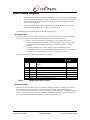
The following sections describe the bits in the fault register by type.
Voltage faults
The CCN samples system voltages and temperatures one hundred times per second. These readings
are averaged to reduce noise and then compared against a table of expected values.
• When a voltage is outside of its defined range, it will be registered as a fault.
• The current, minimum, and maximum voltage readings, as well as the upper and
lower limits of their acceptable ranges, may be inspected using the “voltages”
command.
• To disable monitoring of a specific voltage, set the corresponding bit in the
VOLTMASK register to one. The minimum and maximum will still be recorded, but
the voltage’s value will no longer cause a fault, regardless of its value.
Table 8 below lists the voltages monitored by the CCN-cPCI:
Bit
#
0
Name
Description
TEMP0
Temperature in degrees C measured on CCN
board.
1
2
3
4
5
6
7
ALM12A
ALM12B
PCIP12
PCIN12
PCIP5
UNUSED
PCIP3
Voltage on CCN 12V power feed A
Voltage on CCN 12V power feed B
Voltage on PCI backplane +12V
Voltage on PCI backplane –12V
Voltage on PCI backplane +5V
Unused
Voltage on PCI backplane +3.3V
Table 8
Normal
range
5-40
11.0 – 13.0
11.0 – 13.0
11.0 – 13.0
-10.0 – -13.0
4.5 – 6.0
--2.8 – 3.8
Voltages monitored by CCN-cCPI
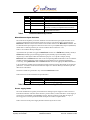
Presence faults
The CCN-cPCI has the ability to detect the removal of many components of a fault group. If one of
these components is removed when it is expected to be present, then a fault will be generated.
To prevent such a fault when removal of a unit is desired, the corresponding bit in the EQUIP register
must be cleared. The presence or absence of that unit will then be ignored for computing faults, but
the correct status will still be shown when the “presence” command is used.
Continuous Computing Corporation
Proprietary and Confidential
Page 26 of 34
CCN Reference Manual
CC00274-08.doc
Last saved: 10/25/2001 5:44 PM
Table 9 below lists the presence bits detected by the CCN-cPCI.
Bit #
8
9
10
11
12
Name
PWRAPRES
PWRBPRES
DSKAPRES
DSKBPRES
SWAPPING
13
CPUPRES
Table 9
Description
Power supply A (left supply or only supply)
Power supply B (right supply in two-supply node)
Primary hard disk (boot disk or top disk)
Secondary hard disk (application disk or bottom disk)
CCN ejector latch handle (someone is about to eject
the CCN). Currently not implemented in hardware.
cPCI CPU presence detect. Currently not
implemented in hardware.
Presence bits detected by CCN-cCPI
Miscellaneous input fault bits
The CCN has the capability to monitor and detect two miscellaneous input signals and take one of
several pre-defined actions when these signals are received. The action taken is specified by the
monitor command. Please refer to Section 4 for further details on the monitor command. The
two miscellaneous input signals are delivered to the CCN via pin 4 (MISCIN0) and pin 5 (MISCIN1)
which share a common ground on pin 6 on the CCPUnet RJ-45 connectors. See
Table 15 for CCPUnet RJ-45 pin diagram.
A miscellaneous input fault is triggered if monitor mode is set to falm-nc (normally closed) or
falm-no (normally open) and the appropriate signal (normally open and normally closed,
respectively) is detected on either miscellaneous input pins. As a specific example, setting
monitor mode to falm-nc will result in the corresponding MISCIN fault bits to be set when the
normally closed miscellaneous inputs (which are being pulled low) are opened and pulled high.
Conversely, setting monitor mode to falm-no will result in the appropriate MISCIN fault bits
to be set when the normally open miscellaneous inputs (which are being pulled high) are closed and
pulled low. A common use for the miscellaneous inputs is to monitor fan trays and alarm upon the
detection of a fan failure.
No faults or alarms are generated in any of the other monitor modes.
Table 10 below lists the miscellaneous input fault bits.
Bit #
14
15
Table 10
Name
MISCIN0
MISCIN1
Description
Miscellaneous input 0
Miscellaneous input 1
Miscellaneous input fault bits detected by CCN-cCPI
Power supply faults
The CCN communicates regularly with Continuous’ intelligent power supplies to detect current or
latent fault conditions. The most basic check is a presence detect, as described above. If the supply is
present and is not disabled in the DISABLE register, then the CCN will verify that the supply is
receiving power on each input feed and that its outputs are within acceptable limits.
Table 11 below lists the power supply fault bits detected by the CCN-cCPI.
Continuous Computing Corporation
Proprietary and Confidential
Page 27 of 34
CCN Reference Manual
CC00274-08.doc
Last saved: 10/25/2001 5:44 PM
Bit #
16
Name
PWAFEEDA
Description
Supply A 48V feed A bad
17
PWAFEEDB
Supply A 48V feed B bad
18
PWAOUTBD
Supply A outputs bad
19
RSVD
Reserved
20
PWBFEEDA
Supply B 48V feed A bad
21
PWBFEEDB
Supply B 48V feed B bad
22
PWBOUTBD
Supply B outputs bad
23
RSVD
Reserved
Table 11
Power supply fault bits detected by CCN-cCPI
Application faults
The application running on the host can request a fault through the CCNtalk interface. This fault can
be set to cause a critical, major, or minor alarm.
The application can also enable a watchdog timer on the CCN which will cause a fault if it expires.
Table 12 below lists the application fault bits detected by the CCN-cCPI.
Bit #
24
25
26
27
Table 12
Name
APPMN
APPMJ
APPCR
APPDOG
Description
Application requested minor alarm
Application requested major alarm
Application requested critical alarm
Application watchdog timed out
Application fault bits detected by CCN-cCPI
CCPUnet bus faults
The CCN constantly monitors the data communication on both CCPUnet busses. If no communication is
detected for more than three seconds on either of the CCPUnet busses, the connection is presumed lost and
the appropriate CCN CCPUnet bus error fault bit is set.
Bit #
28
29
Table 13
Name
CCNCAN0
CCNCAN1
Description
CCN CCPUnet A bus error
CCN CCPUnet B bus error
CCPUnet bus fault bits detected by CCN-cCPI
Generating Alarms From Faults
The following are descriptions of the rules used to convert fault states into alarm states.
Critical alarms
•
Single -supply system and power supply is absent or has bad output.
•
Dual-supply system and both supplies are absent or have bad outputs
Continuous Computing Corporation
Proprietary and Confidential
Page 28 of 34
CCN Reference Manual
CC00274-08.doc
Last saved: 10/25/2001 5:44 PM
•
Any PCI voltage out of range (+5V, +3.3V, ±12V).
•
Application heartbeat lost.
•
Application-requested Critical fault.
Major alarms
•
Power supply A is Inhibited, Pullable, or Not Present and power supply B has a
fault.
•
Power supply B is Inhibited, Pullable, or Not Present and power supply A has a fault.
•
Both power supplies have a fault.
•
Either power supply is removed or not present and its EQUIP bit is set.
•
Either hard disk is removed or not present and its EQUIP bit is set.
•
Either +12V feed to the CCN is absent or out of range.
•
Monitor mode is set and either of the miscellaneous input faults is triggered.
•
Application-requested watchdog timer expired.
•
Application-requested Major alarm.
Minor alarms
•
Dual-supply system and one power supply has a fault.
•
Temperature out of range.
•
Either CCPUnet bus has an error.
•
Application-requested Minor alarm.
Continuous Computing Corporation
Proprietary and Confidential
Page 29 of 34
CCN Reference Manual
CC00274-08.doc
Last saved: 10/25/2001 5:44 PM
6 Troubleshooting
This section includes some of the more commo n issues with the proper functioning of the CCN.
As a first step, be sure you have a serial terminal. This can be one of the following:
•
VT100 or compatible
•
Sun system running tip
•
Windows PC laptop with Hyperterm or another terminal program
Serial CLI Connections
Ensure the proper settings
First, make sure your system matches the following factory defaults:
•
38400, 8 data bits, no parity, 1 stop bit.
If you have changed your settings from the factory defaults, you need to change
them back to the defaults.
Note: You change the baud rate or any other setting in Windows Hyperterm, you have to actually
disconnect and then reconnect—using the software commands, not by unplugging the cable—to the
port for the new setting to take effect. This is a bug in Hyperterm.
Check your terminal’s cable
Assuming your serial terminal has a standard PC DB-9 port, then you need a male -female cable with
all pins straight through.
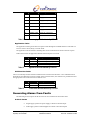
Check the SER3 port
If you are using the front-panel port, make sure nothing else is plugged into SER3 on the back of that
CCN.
The front panel CONS port and the SER3 port on the back are the same physical connection and
cannot both be used at once.
Verify your terminal is sending and receiving correctly
You can verify that your serial terminal is sending/receiving correctly by shorting pins 2 and 3 on the
male end of the cable with a loopback plug or screwdriver – then, when you type, you should see an
echo. This does not check the baud, but it does makes sure you are opening the correct COMx: device
(on a laptop, it’s not always obvious exactly what is what).
Disconnect CCN CLI from the Sun console
The last person to use the console port may have used a connect command and left it that way. If
this is the case, you are sending characters to the remote CPU.
Possible solution: Press Ctrl-] to see if you get a connected to xx prompt. If so, then
type exit and you'll be back at the CLI.
Continuous Computing Corporation
Proprietary and Confidential
Page 30 of 34
CCN Reference Manual
CC00274-08.doc
Last saved: 10/25/2001 5:44 PM
Use a lightbox or breakout box
As always, the best way to diagnose serial problems is with a lightbox or breakout box. It’s a good
idea to keep one in your lab, as well as having some DB-9/DB-25 adapters available.
Last-ditch solution: press RESET
As a last-ditch effort to resolve cabling or flow-control problems:
1. Make sure everything is connected.
2.
Press the RESET switch on the CCN.
Note that this will not reset the Sun CPU unless initmode is set to off. It will
reset the CCN, which causes it to print its banner.
If your problem is related to flow control, somehow preventing the terminal from
transmitting, you should at least receive the banner string at this point.
Contact Technical Support
If all of the above fail, contact the Technical Support team at Continuous Computing. See Section 8
for contact information.
Continuous Computing Corporation
Proprietary and Confidential
Page 31 of 34
CCN Reference Manual
CC00274-08.doc
Last saved: 10/25/2001 5:44 PM
7 Pinouts and Specifications
Serial DCE (DB-9)
1
Pin #
1
2
3
4
5
6
7
8
9
6
9
5
viewed from
board end
Table 14
Signal
DCD
RXD
TXD
DTR
GND
DSR
RTS
CTS
Not used
In/Out
Out
Out
In
In
Out
In
Out
Serial DCE (DB-9) pinout
CCPUnet (RJ-45)
Pin 8
Pin 1
RJ45 male connector viewed from connection end
Table 15
Pin
Signal
1
2
3
4
5
6
7
8
Relay Normally Open
Relay Common
Relay Normally Closed
Miscellaneous Input 0
Miscellaneous Input 1
Ground
CCPUnet High
CCPUnet Low
CCPUnet (RJ-45) pinout
Continuous Computing Corporation
Proprietary and Confidential
Page 32 of 34
CCN Reference Manual
CC00274-08.doc
Last saved: 10/25/2001 5:44 PM
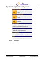
Specifications (Preliminary/Expected)
Operating Environmental
Temperature
Humidity
Altitude
-5°C to 50°C (Operating)
5% to 90% relative humidity, noncondensing
3000m
Storage/Transit Environmental
Temperature
Humidity
Altitude
-40°C to 70°C
5% to 95% relative humidity, noncondensing
10000m
Power
Voltage
Current
Two 12VDC feeds
500mA total
Safety Compliance
UL/cUL1950 3rd Edition Recognized Component
UL/cUL1950 Listed (Systems only)
European Low Voltage Directive (Systems only)
Electromagnetic Compatibility (EMC)
FCC Class A
European EMC Directive (Systems only)
Telco Compliance
Telcordia NEBS GR-63-CORE Level 3
Telcordia NEBS GR-1089-CORE Level 3
Marks
UL, cUL, CE (Systems only)
Table 16
Specifications
Continuous Computing Corporation
Proprietary and Confidential
Page 33 of 34
CCN Reference Manual
CC00274-08.doc
Last saved: 10/25/2001 5:44 PM
8 Technical Support
Before contacting the Technical Support team at Continuous Computing, be sure you have read
Section 6, “Troubleshooting,” of this guide.
If you continue to experience problems with the Continuous Control Node, please contact the
Technical Support team at Continuous Computing by any of the methods listed below.
Note: Please be sure to include the serial numbers for each affected module, system and/or part. In
addition, we will need to know what version of Solaris (or other operating system) you are running, as
well as the patch level, and any other significant software packages that are installed.
Contacting Technical Support
To contact the Technical Support team at Continuous Computing, do one of the following:
•
•
•
Email us at [email protected]
Visit our support web site at http://support.ccpu.com
(This site features our automatic technical support system. Create a new user profile.
Then submit a new ticket at the “Welcome to SupportWizard” page. This process ensures
that our team delivers a timely solution to any technical problem you have.)
Call us at (858) 882-8911, 9:00 a.m. – 5:00 p.m. (PST)
Note: If you have a Gold or Platinum service contract, follow the contact instructions provided with
your contract.
Continuous Computing Corporation
Proprietary and Confidential
Page 34 of 34
CCN Reference Manual
CC00274-08.doc
Last saved: 10/25/2001 5:44 PM