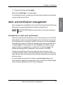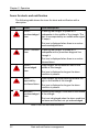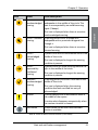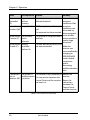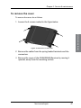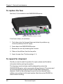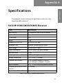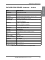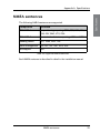
1
SAILOR 65xx GNSS/DGNSS User manual SAILOR 65xx GNSS/DGNSS User manual Document number: 98-140657-A Release date: June 16, 2015 i Disclaimer Any responsibility or liability for loss or damage in connection with the use of this product and the accompanying documentation is disclaimed by Thrane & Thrane A/S. The information in this manual is provided for information purposes only, is subject to change without notice and may contain errors or inaccuracies. Manuals issued by Thrane & Thrane A/S are periodically revised and updated. Anyone relying on this information should acquire the most current version e.g. from www.cobham.com/communications-andconnectivity/satcom, Service and support, or from the distributor. Thrane & Thrane A/S is not responsible for the content or accuracy of any translations or reproductions, in whole or in part, of this manual from any other source. In the event of any discrepancies, the English version shall be the governing text. Thrane & Thrane A/S is trading as Cobham SATCOM. Copyright © 2015 Thrane & Thrane A/S. All rights reserved. Trademark acknowledgements • • • SAILOR is a registered trademark of Thrane & Thrane A/S in the European Union and the Unites States of America and other countries. Other product and company names mentioned in this manual may be trademarks or trade names of their respective owners. This product contains Android™ software. Android is a trademark of Google Inc. GPL notification The software included in this product contains copyrighted software that is licensed under the GPL/LGPL. The verbatim licenses can be found online at: http://www.gnu.org/licenses/old-licenses/gpl-2.0.html http://www.gnu.org/licenses/old-licenses/lgpl-2.1.html You may obtain the complete corresponding source code from us for a period of three years after our last shipment of this product, which will be no earlier than 2021, by sending a money order or check for DKK 50 to: SW Technology/GPL Compliance, Cobham SATCOM (Thrane & Thrane A/S), Lundtoftegaardsvej 93D 2800 Lyngby DENMARK Write "source for product GNSS/DGNSS Receiver" in the memo line of your payment. This offer is valid to anyone in receipt of this information. http://www.cobham.com/about-cobham/communications-and-connectivity/aboutus/satcom/free-and-open-source-software-(foss).aspx ii Safety summary Observe the following general safety precautions during all phases of operation, service and repair of this equipment. Failure to comply with these precautions or with specific warnings elsewhere in this manual violates safety standards of design, manufacture and intended use of the equipment. Thrane & Thrane A/S assumes no liability for the customer's failure to comply with these requirements. Ground the equipment To minimize shock hazard, connect the GNSS/DGNSS Receiver to an electrical ground and follow the cable instructions. Warranty limitation IMPORTANT - The SAILOR 6286 DGNSS Antenna - Active and the SAILOR 6285 GNSS Antenna - Active are sealed waterproof units (classified IPx6 & IPx8). To create and maintain its waterproof integrity the antenna was assembled in a controlled environment using special equipment. The antennas and the GNSS/DGNSS Receiver are not user maintainable units, they should under no circumstances be opened except by authorized personnel. Unauthorized opening of the unit will invalidate the warranty. Installation and service Installation and general service must be done by skilled service personnel. Compass safe distance Compass safe distance: 30 cm (Standard magnetic compass), 20 cm (Emergency magnetic compass) from the GNSS/DGNSS Receiver. iii Preface Approvals The GNSS/DGNSS Receiver is approved to MED 2011/75/EU and fulfills the requirements in the standards: IEC 61108-1 Ed. 2.0, 2003 IEC 61108-2 Ed. 1.0, 1998 IEC 61108-4 Ed. 1.0, 2004 IEC 61162-1 Ed. 4.0, 2010 IEC 61162-2 1998 IEC 61162-450 2011 IEC 60945 Ed. 4, 2002 MSC.302(87) The approvals of the GNSS/DGNSS Receiver are constantly monitored. New national approvals will be applied for and granted and new test standards may come into force. Therefore the above list may not be complete. Contact your authorized dealer for more information. About the manual Intended readers This manual is a user manual for the GNSS/DGNSS Receiver. This manual is intended for anyone who is using or intends to use this system. It is important that you observe all safety requirements listed in the beginning of this manual, and operate the system according to the guidelines in this manual. Note that this manual does not cover installation of the system. For information on installation refer to the installation manual. Part numbers for related manuals are listed in the next section. iv Related documents The following table shows the documents related to this manual and to the GNSS/DGNSS Receiver. Title and description Document number SAILOR 6588 GNSS/DGNSS Receiver, Installation manual 98-145263 SAILOR 6004 Control Panel, Installation manual 98-136644 SAILOR 6588 GNSS/DGNSS Receiver, Installation guide 98-140656 SAILOR 6286 DGNSS Antenna - Active, Installation guide 98-141644 SAILOR 6285 GNSS Antenna - Active, Installation guide 98-136019 Typography In this manual, typography is used as indicated below: Bold is used for the following purposes: • To emphasize words. Example: “Do not touch the antenna”. • To indicate what the user should select in the user interface. Example: “Select SETTINGS > LAN”. Italic is used to emphasize the paragraph title in crossreferences. Example: “For further information, see Connecting Cables on page...”. v vi Table of contents Chapter 1 Introduction Introduction to GNSS and DGNSS ...............................................1 Overview ...................................................................................................................... 1 The GNSS or DGNSS system ...........................................................2 System configuration ............................................................................................ 4 System components ...........................................................................4 SAILOR 6588 DGNSS Receiver ......................................................................... 4 SAILOR 6285 GNSS Antenna - Active ........................................................... 5 SAILOR 6286 DGNSS Antenna - Active ........................................................ 6 SAILOR 6004 Control Panel ............................................................................... 6 Chapter 2 Operation To get started .........................................................................................7 To dim the display of the Control Panel ....................................................... 7 Startup screen ........................................................................................................... 8 GNSS/DGNSS menu screen ............................................................................. 10 Position ................................................................................................... 11 Anchor Watch ..................................................................................... 19 Trip Counters ....................................................................................... 21 Settings ................................................................................................... 23 To change a setting ............................................................................................. 23 Settings – General ................................................................................................ 24 Settings – Radio Beacons ................................................................................. 29 Settings – Alerts .................................................................................................... 30 Alert and notification management ......................................... 31 List of alerts .......................................................................................... 35 Multiple receivers .............................................................................. 37 Alerts and notifications in a multiple-receiver system ....................... 38 vii Table of contents Chapter 3 Service & maintenance Maintenance ........................................................................................ 39 Contact for support .............................................................................................39 Service interface ....................................................................................................40 System LEDs ............................................................................................................42 Troubleshooting guide .................................................................... 43 Service and repair .............................................................................. 45 Applicable SAILOR part numbers ...................................................................45 Accessories ...............................................................................................................46 To remove the cover ...........................................................................................47 To replace the fuse ...............................................................................................48 To repack for shipment ......................................................................................48 App. A Specifications SAILOR 6588 GNSS/DGNSS Receiver ...................................... 51 SAILOR 6285 GNSS Antenna - Active ..................................... 52 SAILOR 6286 DGNSS Antenna - Active .................................. 53 SAILOR 6004 Control Panel ......................................................... 54 NMEA sentences ................................................................................ 55 Glossary ..................................................................................................................... 57 Index ..................................................................................................................... 59 viii 11111 Chapter 1 Introduction Introduction 1 This chapter introduces the GNSS/DGNSS Receiver and gives an overview of the system and services. It has the following sections: • Introduction to GNSS and DGNSS • The GNSS or DGNSS system • System components Introduction to GNSS and DGNSS Overview A GNSS receiver processes the signals transmitted by the satellites of Global Navigation Satellite Systems (GNSS). The GNSS receiver determines the position, velocity, and precise time by processing the signals broadcast by GNSS satellites. A DGNSS receiver (Differential GNSS) is an enhancement to a GNSS receiver. It can utilize a global network of ground-based reference stations for improved position accuracy. The ground-based reference stations compare their known fixed positions with the positions calculated from the received GNSS satellite signals. The differences are transmitted via radio beacons to the DGNSS Receiver, which can use them to calculate a more precise position. In order to be able to apply high-quality corrections, the selected reference station must be near the DGNSS receiver to ensure that they both observe roughly the same GNSS satellites. 1 Chapter 1: Introduction The GNSS or DGNSS system The GNSS/DGNSS Receiver is available in variants as listed in table 1. Depending on the antenna used the Receiver will either be a GNSS or a DGNSS Receiver. Using the SAILOR 6285 GNSS Antenna - Active gives a GNSS Receiver variant and the SAILOR 6286 DGNSS Antenna - Active gives a DGNSS Receiver variant. Both variants can be controlled by the SAILOR 6004 Control Panel. The Control Panel is connected to the GNSS/DGNSS Receiver through a LAN connection. Features Position calculation with GPS and/or GLONASS satellites. Reception and use of differential corrections from SBAS, RTCM SC-104 via a serial interface or the integrated radio beacon receiver.1 RAIM calculation according to IEC 61108-1. Estimates the calculated positions accuracy and monitors the signal integrity. SBAS corrections from EGNOS, MSAS, WAAS, GAGAN and SDCM. Automatic or manual radio beacon station selection.1 Support for other datums, including a user defined. Serial inputs and outputs according to IEC 61162-1/2. Fully configurable for each port. Light Weight Ethernet interface according to IEC 61162-450. Fully configurable. Alert management according to MSC.302. Fully configurable. Support for High Speed Craft (HSC). Antenna offset correction. Anchor Watch. 1. DGNSS only 2 The GNSS or DGNSS system 11111 Chapter 1: Introduction Introduction Two Trip Counters and a total counter. Speed log output. Pulse Per Second (PPS) output. Interface for ThraneLink applications and INS available. Touch screen on the SAILOR 6004 Control Panel. Possibility for multiple-receiver setup with up to three GNSS/DGNSS Receivers. Up to four Control Panels on the same GNSS/DGNSS Receiver. System variants The following variants are available: DGNSS GNSS DGNSS Control Receiver antenna antenna Panel Variant SAILOR 6560 GNSS System x x x SAILOR 6561 GNSS Basic x x SAILOR 6570 DGNSS System x x SAILOR 6571 DGNSS Basic x x x Table 1: System variants All variants include the DGNSS or GNSS App for the Control Panel. The application is an integrated part of the GNSS/DGNSS Receiver. The GNSS or DGNSS system 3 Chapter 1: Introduction System configuration The following figure shows the units of a GNSS or DGNSS system. SAILOR 6285 SAILOR 6286 GNSS Antenna - Active DGNSS Antenna - Active RAIM Power CORR SAILOR 6588 DGNSS Receiver SAILOR 6004 Control Panel PWR TEST AUX ACC 6588 DGNSS Receiver 12-24 VDC 12-24 VDC Figure 1: System configuration System components SAILOR 6588 DGNSS Receiver The DGNSS Receiver is the main unit in a DGNSS or GNSS position system. The DGNSS Receiver is always on, provided there is DC power. It has a connector for the GNSS or DGNSS antenna, a ground connection, springloaded terminals for DC power (12–24 VDC) and a dual LAN connector. The DGNSS Receiver has spring-loaded terminals for connection to various inputs and outputs. 4 System components 11111 Introduction Chapter 1: Introduction Figure 2: SAILOR 6588 DGNSS Receiver SAILOR 6285 GNSS Antenna - Active The SAILOR 6285 GNSS Antenna - Active is a robust, sealed and waterproof GPS and GLONASS antenna (classified IPx6 & IPx8). Figure 3: SAILOR 6285 GNSS Antenna - Active System components 5 Chapter 1: Introduction SAILOR 6286 DGNSS Antenna - Active The SAILOR 6286 DGNSS Antenna - Active is a robust, sealed and waterproof GPS and GLONASS antenna. This antenna also has an antenna for receiving differential corrections from radio beacon stations in the LW frequency band. Figure 4: SAILOR 6286 DGNSS Antenna - Active SAILOR 6004 Control Panel The Control Panel is the user interface for the GNSS/DGNSS Receiver. Alerts are shown in the display. The Control Panel has a touch screen and a buzzer for alert tones. The display can be dimmed. The Control Panel has a color LCD screen and the nominal viewing distance is 0.9 m. Figure 5: SAILOR 6004 Control Panel 6 System components 22222 Chapter 2 This chapter has the following sections: • To get started • Position • Anchor Watch • Trip Counters • Settings • Alert and notification management • List of alerts • Multiple receivers 2 Operation Operation To get started As soon as DC power is provided the GNSS/DGNSS Receiver is on. To switch on the Control Panel push the power button. Operate the Control Panel by tapping the touch screen. To switch off the Control Panel push and hold the power button for 2 seconds and follow the instructions on the screen. Note If the remote switch in the Control Panel is wired and it is switched on, you can only use the Power button to reboot the Control Panel, you cannot switch it off. To dim the display of the Control Panel Turn the dim knob of the Control Panel to increase or decrease the display brightness or tap Auto. To dim to level zero push the power button once. If an alert appears while the display is in level zero, the display returns to the latest dim value and the alert is displayed. 7 Chapter 2: Operation Startup screen The Control Panel is a multipurpose touch display on which the DGNSS or GNSS application has been installed during the installation of the GNSS/DGNSS Receiver. The startup screen provides an icon-based application menu including the DGNSS or GNSS application. To start the DGNSS or GNSS application tap the DGNSS or GNSS icon on the Control Panel display. Figure 6: Startup screen (example for DGNSS) The application menu also includes the general Control Panel System application providing application management and general Control Panel settings. For details see the installation manual of the Control Panel. Bottom bar The general bottom bar of the Control Panel is always available below the startup application menu or the currently running application. Figure 7: Bottom bar The left side of the bottom bar contains general navigation icon buttons: Back button 8 To get started 22222 Chapter 2: Operation Tap the back button to return to the previous screen/page of the current application or close the current application. If you tap this icon when being in the GNSS or DGNSS menu screen, you navigate to the startup screen. Hide keyboard button Operation Tap the hide keyboard button to remove the on screen keyboard. This button replaces the back button when the on screen keyboard is shown. Home button Tap the home button to return to the startup screen. The right side of the bottom bar contains indication icons (if there are any active indications) from alert or notifications and contains also the UTC time. Tap this area to open the alert and notifications list. Figure 8: Alerts and notifications Tap the same area again or tap the back button to close the list. See Alert and notification management on page 31 for more details on alerts and notifications. To get started 9 Chapter 2: Operation GNSS/DGNSS menu screen Tap the DGNSS or GNSS icon on the startup screen to display the menu screen. From this screen you access the main functions of the GNSS/DGNSS Receiver. Figure 9: Menu screen (example for DGNSS) Tap Position, Anchor Watch, Trip Counters or Settings to proceed. Note 10 The following sections describe the DGNSS app. The functionality that is not available in the GNSS system will be marked as DGNSS only. To get started 22222 Position The Position screen gives an overview of the current position and other relevant status information. This screen has the tabs Overview and Quality. Lists of GNSS satellites, SBAS satellites, beacons and beacon messages can be accessed through the icon in the upper right corner. When no position is calculated or the connection to the GNSS/DGNSS Receiver is lost, the position information in this screen is frozen and the text color is changed to yellow. Figure 10: Position screen (example) The following paragraphs describe the Overview tab. Top information line UTC time RAIM (Limit) Position delta Datum Figure 11: Top information line The UTC time in the position screen is the time of the displayed position. When the position is lost this time does not change. The RAIM status gives an indication of the quality of the calculated position. A result of the RAIM calculation is the estimated position Position 11 Operation Chapter 2: Operation Chapter 2: Operation accuracy, indicated in POSN field in the top information line. The estimated position accuracy is compared to the RAIM accuracy limit yielding the RAIM status. The RAIM accuracy limit is shown in parentheses. You can set the accuracy limit in DGNSS > Settings > Accuracy RAIM. Status Explanation Safe The RAIM status is safe. The position accuracy is below the set accuracy limit. Caution The RAIM status is caution. There are not enough satellites available to calculate RAIM. Unsafe The RAIM status is unsafe. The position accuracy has exceeded the set accuracy limit. Table 2: RAIM status The datum used for the current position is displayed to the right. For example WGS 84. You can set the datum in DGNSS > Settings > General > Datum. Latitude and longitude of the calculated position Figure 12: Latitude and longitude (example) “LED” status section: The color “LED”s indicate the status of the system. Green color of the “LED” means no issues (i.e. satellite system is used for position or valid beacon data currently received) and amber color means there is an issue (i.e. satellite system is not used for position or no valid beacon data currently received). 12 Position 22222 Figure 13: “LED” status section (example) Depending on the selected satellite system, the name of the system and an "LED" is listed in the LED status section. You can configure which systems to use in DGNSS > Settings > General > Use GNSS Systems. The name of the GNSS System may have a prefix, see the following table. Prefix Configured differential use None No differential corrections D Use of differential corrections from a beacon S Use of differential corrections from SBAS Table 3: Prefix of GNSS systems When the use of differential corrections is configured, the status of the corrections is displayed with a text corresponding to the mode and a status “LED”. You can configure differential corrections in DGNSS > Settings > General > Differential Beacon Correction. Text Mode DGNSS GNSS AUTO XXX Automatic mode, the beacon is automatically selected by the DGNSS Receiver. XXX is the reference ID of the beacon. X MAN XXX Manual mode, the beacon is manually selected by the user. XXX is the reference ID of the beacon. X Xxx.x kHz The DGNSS Receiver has tuned to the frequency Xxx.x kHz. The frequency has been either manually configured or was provided by an external device. X Ext. RTCM Differential corrections come from an external source. X Table 4: Status of the differential corrections Position 13 Operation Chapter 2: Operation Chapter 2: Operation COG/SOG section This section displays the Course Over Ground (COG) and the Speed Over Ground (SOG). The COG and SOG are calculated together with the position and are only shown when the position is updated. COG is the average direction travelled in the time set by COG Smoothing (DGNSS > Settings > General > COG Smoothing). SOG is the average speed, calculated over the SOG Smoothing time (DGNSS > Settings > General > SOG Smoothing). Figure 14: COG/SOG section Quality tab The Quality tab provides more detailed information about the current position. 14 • Satellites in view shows the number of satellites above the minimum elevation mask. • Satellites in use shows the number of satellites used for calculating the position. • Correction age is the age of the currently applied differential corrections. • Correction reference is the reference ID of the radio beacon station in use. Position 22222 Operation Chapter 2: Operation Figure 15: Quality of the position data When using SBAS corrections, Correction method shows SBAS and Correction reference shows the set SBAS correction system. You can set the SBAS Correction System in DGNSS > Settings > SBAS Correction System. Correction age is left blank as this information is not available for SBAS corrections. Figure 16: Using SBAS corrections Position 15 Chapter 2: Operation Lists of GNSS and SBAS satellites, beacons and beacon messages Tap to display lists and details of the following: • GNSS satellites (GPS or GLONASS) • SBAS satellites • Beacons1 • Beacon messages1 In the list of SBAS satellites you can tap a satellite and display further details. DGNSS only: In Beacons you can do the following: • Tap Current to see the currently selected beacon. • Tap Nearest to see a list of the nearest 10 beacons and select one. • Tap All to see a list of all beacons known to the DGNSS Receiver. The beacons shown in the tab All are from the internal database. The database is updated from almanac data sent from the beacon stations around the world. The database can contain 2000 stations. Figure 17: DGNSS Beacons - Current beacon The signal strength is good if it is higher than 30 dBV. The signal-to-noise ratio is good if it is higher than 8 dB. 1. DGNSS only. 16 Position 22222 There are several ways to configure the beacon selection: • Tap > Automatic Mode to have the DGNSS Receiver automatically decide which beacon to use to achieve the most precise position. • Tap > Manual Mode to manually select the frequency and bit rate of the desired beacon. The frequency range is 283.5 - 325.0 kHz, bit rates are Auto, 25, 50, 100 and 200. To lock the DGNSS Receiver to use a specific beacon do as follows: 1. Tap Nearest or All, Tap to sort in ascending or descending order Figure 18: List of closest beacons The selected, active beacon is always the first entry in the list. It has a white antenna symbol. Next to the antenna symbol is an indicator, showing the status of the beacon station. If there is no indicator it is not possible to receive the beacon station at the moment. You can sort the beacon list by Distance, Id, Name and Frequency by tapping the item in the heading line. Position 17 Operation Chapter 2: Operation Chapter 2: Operation Beacon indicator Explanation A Current beacon. Automatically selected. M Current beacon. Manually selected. Green dot Healthy beacon. Yellow dot Unhealthy beacon. Do not use under any circumstances. Gray dot Unmonitored beacon. Do not use unless no other station is available. Table 5: Beacon indicators 2. Tap a beacon. A window pops up showing the details of the transmit station. Figure 19: Details for a selected beacon 3. Tap Lock and tap OK to confirm. To unlock select Automatic mode or lock on another beacon. 18 Position 22222 Chapter 2: Operation Anchor Watch Operation The anchor watch feature informs you if the vessel has moved and has exceeded the intended anchoring position (Watch reference position). The GNSS/DGNSS Receiver will come up with an alert if the alert distance (Alert dist) is exceeded. Figure 20: Anchor Watch Tap the button Activate to activate the anchor watch. To set the alert distance, do as follows: 1. Tap the button Set Alert Distance. 2. Swipe to set the desired alert distance. 3. Tap OK to confirm. Anchor Watch 19 Chapter 2: Operation Figure 21: Alert Distance for Anchor Watch (example) When Anchor Watch is active multiple indicators appear: The double circle indicates the position of the vessel (1), the cross in the middle indicates the Watch reference position (2) and the outer circle indicates the alert distance (3). The position of the vessel is always shown relative to the Watch reference position. If the position of the vessel exceeds the alert distance the alert distance circle will shrink to be able to show the position of the vessel beyond the alert distance. (2) (1) (3) Figure 22: Anchor Watch - vessel and watch reference position 4. To terminate the Anchor Watch function tap the button Terminate. 20 Anchor Watch 22222 Trip Counters The GNSS/DGNSS Receiver has two trip counters and a total counter. The trip counters are updated when the system is switched on and a valid position is available. When the system is switched on, but there is no valid position, the travelled distance will be added to the counters when a position is obtained again. The trip counter one and two can be reset. The total counter is reset after a reset to factory default settings of the GNSS/DGNSS Receiver. Figure 23: Trip Counters (example) Trip Counters 21 Operation Chapter 2: Operation Chapter 2: Operation To see details about the trip, tap the trip counter of interest. Figure 24: Trip Counter (example) To reset a counter do as follows: 1. Tap the trip counter you want to reset. 2. Tap Reset and OK to confirm. 22 Trip Counters 22222 Settings Note If multiple Control Panels are connected to the GNSS/DGNSS Receiver the operator shall be aware of the possibility that complementary Control Panels may be operated simultaneously. The latest setting values in the GNSS/DGNSS Receiver are always synchronized to all Control Panels. The GNSS/DGNSS Receiver has several sets of settings: General, Radio Beacons and Alerts. You can set these according to your requirements. Figure 25: Settings To change a setting To change a setting, do as follows: 1. Tap DGNSS > Settings 2. Tap the tab General, Radio Beacons or Alerts. 3. Swipe upwards to display further settings. 4. Tap the setting you want to change. 5. Select or set the setting according to your requirements. 6. Tap Apply. Settings 23 Operation Chapter 2: Operation Chapter 2: Operation Settings – General General Description Use GNSS Systems Select one of the following: SBAS Correction System • GPS (default) • GLONASS • GPS / GLONASS Select one of the following: • Disabled (no SBAS correction) (default) • Automatic (Selects the most suitable correction system, see below) • EGNOS (Europe) • MSAS (Japan) • WAAS (North America and Hawaii) • GAGAN (India) • SDCM (Russia) Enabling the use of an SBAS Correction System is on your own responsibility. Note that beacon corrections have precedence over SBAS corrections. Accuracy RAIM Select the RAIM accuracy limit used in the RAIM calculations. An alert will be reported when the limit is exceeded. Default: 10 m HDOP Limit Swipe to change the HDOP limit. An alert will be reported when the limit is exceeded. Default: 4 Table 6: General settings 24 Settings 22222 Chapter 2: Operation General Description Minimum Satellite Elevation Set the minimum satellite elevation above the horizon. Default value: 5 degrees Operation Satellites with a low elevation may have a bad signal-tonoise ratio (SNR). Increase the elevation angle to exclude satellites with a low elevation angle. This reduces the number of satellites used to calculate the position which may therefore be less accurate. In the tab Position > Quality you can see the number of satellites in view and in use. In the Position screen tap and select GNSS Satellites. Here you can see lists of satellites. Datum Swipe to select the geodetic datum that the GNSS/DGNSS Receiver should use. • WGS 84 (default) • WGS 72 • User Defined • SGS 85 (MIT ‘93) • PE 90 (used with GLONASS) • IHO Datum • SK 42 • SK 95 • HSC 2011 For User Defined and IHO Datum see To set a local Datum on page 27. COG Smoothing Adjustment of the responsiveness. Increase this setting to avoid rapid fluctuations in COG. The greater the smoothing value is set to, the longer will it take for the COG to reflect when the ship turns. Default: 5 s Table 6: General settings (Continued) Settings 25 Chapter 2: Operation General Description SOG Smoothing Adjustment of the responsiveness. Increase this setting to avoid rapid fluctuations in SOG. The greater the smoothing value is set to, the longer will it take for the SOG to reflect changes in ship speed. Default: 5 s Zone Time Swipe to set the zone time. Format: +/- hh:mm Default: 00:00 This offset is transmitted in the NMEA sentence ZDA. Distance Unit Select a distance unit: • Nautical Miles (default) • Nautical Miles, feet < 1 NM • Nautical Miles, meters < 1 NM • Kilometers • Kilometers, meters < 1 NM • Statute Miles • Statute Miles, feet < 1 mi • Statute Miles, meters < 1 mi Velocity Unit Select a velocity unit: • Knots (default) • Kilometers per hour • Stature Miles per hour Table 6: General settings (Continued) 26 Settings 22222 Chapter 2: Operation To set a local Datum IHO Datum The local datums are implemented according to the "Users handbook on datum transformations involving WGS84", 3rd. edition from the International Hydrographic Organization. Operation To set up an IHO datum do as follows: 1. Tap Settings. 2. Swipe upwards to display Datum, then tap Datum. 3. Swipe to select IHO Datum in the list on the right side of the screen. Figure 26: IHO Datum setup 4. Tap Area, then select on the right side the area for which the datum is used. 5. Tap IHO Datum and swipe on the right side of the screen to select the local geodetic datum from the list. Settings 27 Chapter 2: Operation In some of the datums you must select a Subdivision. See an example in the next figure. Figure 27: Selection of a subdivision (example) 6. Tap Apply to use the datum for position calculation. User Defined If you want to use a local datum that is not in the list you can enter a user defined datum. Note that the values in the user defined datum are relative to WGS 84. To set up a user defined datum do as follows: 1. Tap Settings. 2. Swipe upwards to display Datum, then tap Datum. 3. Swipe to select User Defined in the list on the right side of the screen. 4. Tap each field and enter the values corresponding to the map you are using in the number pad. If the entered value is not in the valid range a red x is shown on the right side of the value field. 28 Settings 22222 Chapter 2: Operation Operation 5. To display the valid range tap and hold the field. Figure 28: To display the valid range (example) Settings – Radio Beacons Radio Beacons Description Differential Beacon Correction Select one of the following: • Enabled (default) • Disabled In GNSS systems the setting Differential Beacon Correction is replaced by External RTCM Correction. RTCM Correction This parameter sets the maximum allowed age for Age correction data. Range: 10-900 s Default: 120 s Note: When increasing the allowed correction age, ensure that the new setting meets your requirements as accuracy may degrade with increasing correction age. Table 7: Settings for radio beacons Settings 29 Chapter 2: Operation Settings – Alerts The following alerts can be set to enabled (default) or disabled in the GNSS/DGNSS Receiver: • HDOP Exceeded (password protected) • Loss of Position (password protected) • Differential Integrity Status (password protected) • RAIM Status - Unsafe • RAIM Status - Caution • Heading Lost • Anchor Watch Alert Password protection Some alert settings are password protected against unauthorised or accidental use. This is marked with a padlock. Figure 29: Password protection – example To unlock a setting with password protected parameters do as follows: 1. Tap the setting you want to change. 2. Enter the user level password (default: user). 3. Tap Apply. 30 Settings 22222 Chapter 2: Operation 4. Change the setting and tap Apply. When leaving Settings, it is locked again. Alert and notification management Alert management is handled by the Control Panel. Note that the following description is a general description of alerts and notification. Note The GNSS/DGNSS Receiver reports alerts of the type warning or caution. Introduction to alerts and notifications Alerts are reported and indicated by icons in the bottom bar of the Control Panel display. An alert is presented together with its alert text. An alert can be of the type alarm, warning or caution. If an alarm is not acknowledged the audible alarm signal (3 beeps) is repeated every seventh second until it is acknowledged. If a warning is not acknowledged the audible warning signal (2 beeps) is repeated every minute until it is acknowledged. The audible warning signal also disappears if the condition is rectified. The alert list is prioritized. The most important alert is an alarm, then warning and finally caution. The most important active alerts move to the top of the list, after that the alerts with the same importance are sorted by activation time. You can display the current list of active, unacknowledged alerts and notifications by tapping the lower right corner of the Control Panel display where the alert indication and UTC time is displayed. Alert and notification management 31 Operation For information how to change the user level password see the installation manual of the Control Panel. Chapter 2: Operation Icons for alerts and notification The following table shows the icons for alerts and notification with a description. Icon Name Icon description Active A flashing red triangle. A symbol of a unacknowledged loudspeaker in the middle of the triangle. This alarm alert is accompanied by an audible alarm signal (3 beeps). This icon is displayed when there is an active unacknowledged alarm. Active – silenced A flashing red triangle. A symbol of a alarm loudspeaker with a prominent diagonal line through it. This icon is displayed when there is an active silenced alarm. Active – acknowledged alarm A red triangle. An exclamation mark in the middle of the triangle. This icon is displayed as long as the alarm condition is present. Active A red triangle. An arrow pointing towards the responsibility right in the middle of the triangle. transferred alarm This icon is displayed as long as the alarm condition is present. Rectified – A flashing red triangle. A tick mark in the middle unacknowledged of the triangle. alarm This icon is displayed when the alarm condition has been rectified but not yet acknowledged. Table 8: Icons for alerts and notification 32 Alert and notification management 22222 Chapter 2: Operation Name Icon description Active A flashing yellow circle with a symbol of a unacknowledged loudspeaker in the middle of the circle. This warning alert is accompanied by an audible warning signal (2 beeps). This icon is displayed when there is an active unacknowledged warning. Operation Icon Active – silenced A flashing yellow circle. A symbol of a warning loudspeaker with a prominent diagonal line through it. This icon is displayed when there is an active silenced warning. Active – acknowledged warning A yellow circle with an exclamation mark in the middle of the circle. Active responsibility transferred warning A yellow circle. An arrow pointing towards the right in the middle of the circle. This icon is displayed as long at the warning condition is present. This icon is displayed as long at the warning condition is present. Rectified – A flashing yellow circle with a tick mark in the unacknowledged middle of the circle. warning This icon is displayed when the warning condition has been rectified but not yet acknowledged. Caution A yellow square with an exclamation mark in the middle of the square. A caution alert disappears automatically when the caution situation is cleared. Notification A notification can be that a new software version is available. Table 8: Icons for alerts and notification (Continued) Alert and notification management 33 Chapter 2: Operation Alert history The alert history contains alerts of the last 24 hours (or maximum1000 entries).The alert history is cleared when you switch off the Control Panel. The alerts and notifications are not saved. To display the alert history with alerts and notifications do as follows 1. Tap the lower right corner (UTC time). 2. Tap History to display a list of alerts and notifications. You can swipe through the list. 3. Tap an alert to display specific alert information. Alert acknowledgement Active alarms and warnings must be acknowledged. When all active alarms and warnings are acknowledged the icons stop flashing. To acknowledge an alert do as follows: 1. Tap the flashing icon in the lower right corner to display the list with alerts and notifications. 2. Tap the check box next to ACK to acknowledge the alert. Figure 30: Alerts and notifications (example for DGNSS) 34 Alert and notification management 22222 Chapter 2: Operation List of alerts The following alerts may be reported, depending on which alerts are enabled in DGNSS > Settings > Alerts. W: Warning Alert Consequence Reason Operation C: Caution Remedy Anchor Watch Alert (W) Distance from current position Relocate the to reference position vessel. (anchoring position) exceeds alert distance. Differential Possibly Integrity degraded Status (W) position accuracy. Station is marked unhealthy or Select an un-monitored. alternative station. The receiver has not received from station for 10 seconds or more. Word Error Rate (WER) has exceeded 10%. Heading The system will Heading data from an external Lost/invalid not be able to device has not been received (W) apply antenna for 30 seconds. offset. Reconnect the external device delivering heading data. Table 9: List of alerts List of alerts 35 Chapter 2: Operation Alert Consequence Reason HDOP Exceeded (C) Degraded position accuracy. Remedy HDOP has exceeded the user defined threshold. Improve GNSS reception conditions. Bad Loss of No position fix. GNSS reception conditions are reception conditions can position (W) bad. be caused by The antenna has disconnected. electromagnetic RAIM Status: The accuracy The receiver is using less than 6 noise, broken antenna/cable or Caution (C) level is satellites. nearby large unknown. structures. RAIM Status: Possibly The user defined accuracy limit Make the Unsafe (C) unreliable has been exceeded. receiver use position fix. more satellites by changing to GPS/GLONASS mode, disable corrections and/or decreasing satellite elevation limit. Connection The system is The receiver is not powered on. lost to unable to report The connection between the receiver (W) a position. Control Panel and the receiver has been cut. Table 9: List of alerts (Continued) 36 List of alerts Reboot the receiver. Repair the connection between the Control Panel and the receiver. 22222 Chapter 2: Operation Multiple receivers The SAILOR 6588 DGNSS Receiver can be configured to act as primary, secondary or tertiary GNSS receiver, where each receiver can be controlled on the same SAILOR 6004 Control Panel. Operation PWR TEST PPS LOG J21 AUX ACC 12-24VDC + J16 12-24VDC - J17 J12 ON_OUT J14 ALARM IN/OUT ON_IN OUT 1 W3 IN 1 J13 J6 SAILOR 6004 Control Panel J19 J18 W5 W4 IN 2 J15 OUT 2 J22 ALARM ACK SAILOR 6588 DGNSS Receiver SHIP GND J2 LAN NMEA OUT LAN J21 PWR TEST PPS LOG AUX ACC 12-24VDC + J16 12-24VDC ON_IN J12 ON_OUT J14 ALARM IN/OUT J17 OUT 1 W3 IN 1 J13 J6 SAILOR 6004 Control Panel J19 J18 W5 W4 IN 2 J15 OUT 2 J22 ALARM ACK SAILOR 6588 DGNSS Receiver SHIP GND J2 LAN NMEA OUT Figure 31: Multiple receivers in one system Refer to the installation manual, where setup of such a system is explained in details. When configured with multiple receivers the start screen will look different from a stand-alone system. Two or three GNSS or DGNSS icons are shown, each with a number in the bottom left corner, corresponding to the device role of the receiver from which the alert is reported. Multiple receivers 37 Chapter 2: Operation 1 is the primary receiver. 2 is the secondary receiver. 3 is the tertiary receiver. Figure 32: Roles of the GNSS/DGNSS Receiver Tap the GNSS or DGNSS icon on the startup screen to display the menu screen for each receiver. Alerts and notifications in a multiple-receiver system Alerts and notifications are reported by icons in the bottom bar of the Control Panel, like in a stand-alone system with only one receiver. The only difference is that the icons have a number in the bottom left corner, corresponding to the device role of the receiver. Figure 33: Alerts and notifications from GNSS/DGNSS Receivers 38 Multiple receivers 33333 Chapter 3 Service & maintenance This chapter has the following sections: • Maintenance • Troubleshooting guide • Service and repair Maintenance Maintenance of the GNSS/DGNSS Receiver and antennas can be reduced to a maintenance check at each visit of the service staff. Inspect the unit for mechanical damages, salt deposits, corrosion and any foreign material. Due to its robust construction and ruggedness the unit has a long lifetime. Anyway it must carefully be checked at intervals not longer than 12 months – dependent on the current working conditions. Contact for support Contact an authorized dealer for technical service and support of the GNSS/DGNSS Receiver and antennas. Before contacting the authorized dealer you can go through the troubleshooting guide to solve some of the most common operational problems. Software version • GNSS/DGNSS Receiver: Tap System > Applications. Tap the icon in the upper right corner Tap Device List Tap the GNSS/DGNSS Receiver. • GNSS/DGNSS App: Tap System > Applications > DGNSS • Control Panel: Tap System > About > Version On these pages you also find the serial number of the unit. 39 Service & maintenance 3 Chapter 3: Service & maintenance Service interface As long as the service engineer is logged into the Service Interface, the GNSS/DGNSS Receiver does not calculate positions. The Control Panel application shows a Connection lost error. Important All tasks related to installation, service and maintenance are described in the installation manual. Only a service engineer should access the Service Interface directly from the display of the Control Panel. This is useful for software update directly via the Control Panel. Do as follows: 1. Tap System > Applications. 2. Tap > Device list. 3. Tap the device. 4. Tap . Figure 34: Access of the Service Interface 40 Maintenance 33333 5. Tap Service Interface. Figure 35: Access the Service Interface . 6. The service engineer can now tap and password (administrator level). and Login and enter user name Figure 36: Login page of the Service Interface Maintenance 41 Service & maintenance Chapter 3: Service & maintenance Chapter 3: Service & maintenance System LEDs Figure 37: LEDs on the GNSS/DGNSS Receiver LED Description Power Green: Power on. RAIM This LED indicates the quality of the position data. The RAIM accuracy in metres is set in the Control Panel. Green: The RAIM status is safe. Yellow: The RAIM status is caution.There are not enough satellites available to calculate RAIM accuracy. Red: The RAIM status is unsafe. CORR This LED indicates if a correction source is used. A correction source can be SBAS or a beacon. Red: No correction source used. Green with 1 s interval: Beacon station is used Green with 3 s interval: SBAS used Table 10: LEDs on the GNSS/DGNSS Receiver 42 Maintenance 33333 Troubleshooting guide Problem Symptom Remedy The DGNSS Receiver fails to turn on. The green power LED If the power cable is connected directly is off. to the GNSS/DGNSS Receiver then check that the white wire in the power cable is connected to the black wire (-DC). For further details see the Installation manual. Use a volt meter to verify that the 12-24 VDC is OK on the power cable. Check if the fuse is blown. No position fix with GPS and/or GLONASS Check the antenna cable to the antenna. The system status Check that the antenna has free line of LED in the screen Overview sight to the satellites. corresponding to the satellite system is amber. Position is wrong No update of position data The time in the bottom right corner shows -:-- Check if the correct datum is selected. (Settings > General > Datum) All dynamic data (time/date, position) is colored amber on the Control Panel. COG and SOG are shown with ---.-. Check the power supplies, cabling, Ethernet connection between the GNSS/DGNSS Receiver and the Control Panel. Restart both units: GNSS/DGNSS Receiver: remove and connect power, Control Panel: use on/off button. Check that no one has logged into the Service Interface. Select the time source via the System app. See the SAILOR 6004 installation manual. Table 11: Troubleshooting Troubleshooting guide 43 Service & maintenance Chapter 3: Service & maintenance Chapter 3: Service & maintenance Problem Symptom Remedy No beacon correction The (lower) beacon status “LED” in the Overview screen is absent. Check if Differential Beacon Correction/External RTCM Correction (DGNSS/GNSS) is enabled in Settings > Radio Beacons. The CORR LED on the receiver is lit and red. The (lower) “LED” in the Overview screen is amber. Check the antenna cable to the antenna. Check beacon selection mode is correct. Use for example Automatic Mode. The CORR LED on the receiver is lit and red. WARNING: “Differential Integrity status” is active. No SBAS correction Device failure The CORR LED on the Check if SBAS Correction Systems is receiver is lit and red. enabled in Settings. If any of the checks and tests described in this section does not assist in resolving the difficulties experienced in the operation and/or performance of the installation, a fault may have developed in the GNSS/DGNSS System. When contacting an authorized representative, be sure to provide as much information as possible describing the observed behavior - also including the type of the GNSS/DGNSS units, serial number, and software release version. You find this information in the setup menu of the connected Control Panel. Table 11: Troubleshooting (Continued) 44 Troubleshooting guide 33333 Service and repair Should your Cobham SATCOM product fail, please contact your dealer or installer, or the nearest Cobham SATCOM partner. You will find the partner details on www.cobham.com/communications-and-connectivity/satcom where you also find the Cobham SATCOM Self Service Center web-portal, which may help you solve the problem. Your dealer, installer or Cobham SATCOM partner will assist you whether the need is user training, technical support, arranging on-site repair or sending the product for repair. Your dealer, installer or Cobham SATCOM partner will also take care of any warranty issue. Applicable SAILOR part numbers The table below shows the applicable part numbers: Part number Description 406560A-00500 GNSS System 406561A-00500 GNSS Basic 406570A-00500 DGNSS System 406571A-00500 DGNSS Basic 406588A-00500 DGNSS Receiver 406004A-00500 Control Panel 406285A-00500 GNSS Antenna - Active 406286A-00500 DGNSS Antenna - Active Table 12: Part numbers Service and repair 45 Service & maintenance Chapter 3: Service & maintenance Chapter 3: Service & maintenance Accessories The following accessories are included in the delivery: Part number GNSS/DGNSS Receiver 37-207073-000 RJ45 Cat5e STP LAN cable, 5 m 67-138959 Accessory kit containing: 1 A fuse, fuse puller, mounting tool, cable tie, 5 screws M4x20 Torx A2, 5 screws ST ø3.9x33, T20 PAN head, self-tapping Table 13: Part numbers for included accessories (GNSS/DGNSS Receiver) Part number SAILOR 6285 GNSS Antenna - Active 41-135855 GNSS Antenna bracket Table 14: Part numbers for included accessories (SAILOR 6285 GNSS Antenna Active) Part number SAILOR 6286 DGNSS Antenna - Active 41-141001 DGNSS Antenna bracket 67-141936 Screw kit for DGNSS/GNSS antenna: 4 screws, Tuflock, M4x8 mm Table 15: Part numbers for included accessories (SAILOR 6286 DGNSS Antenna Active) 46 Service and repair 33333 To remove the cover To remove the cover, do as follows: 1. Loosen the 4 screws marked in the figure below. Service & maintenance Chapter 3: Service & maintenance Figure 38: Removal of the cover 2. Remove the cables from the spring-loaded terminals and the connectors. 3. Remove the cover of the GNSS/DGNSS Receiver by moving it upwards, away from the mounting surface. Service and repair 47 Chapter 3: Service & maintenance To replace the fuse One fuse (1 A) is installed in the GNSS/DGNSS Receiver. Figure 39: Location of the 1 A fuse If the fuse is blown, do as follows: 1. Track down why the fuse was blown and solve the problem, e.g. incorrect polarity at the DC supply. 2. Power down the GNSS/DGNSS Receiver. 3. Remove the cover by loosening the 4 screws. 4. Take out the old fuse. Use the fuse puller. 5. Insert the new fuse. The fuse rating is 1 A. To repack for shipment Should you need to send the product for repair, please read the below information before packing the product. The shipping carton has been carefully designed to protect the GNSS/DGNSS Receiver and its accessories during shipment. This carton and its associated packing material should be used when repacking for shipment. Attach a tag indicating the type of service required, return address, part number and full serial number. Mark the carton FRAGILE to ensure careful handling. 48 Service and repair 33333 Chapter 3: Service & maintenance Note Correct shipment is the customer’s own responsibility. If the original shipping carton is not available, the following general instructions should be used for repacking with commercially available material. 2. Use a strong shipping container, e.g. a double walled carton. 3. Protect the front- and rear panel with cardboard and insert a layer of shock-absorbing material between all surfaces of the equipment and the sides of the container. 4. Seal the shipping container securely. 5. Mark the shipping container FRAGILE to ensure careful handling. Failure to do so may invalidate the warranty. Service and repair 49 Service & maintenance 1. Wrap the defective unit in heavy paper or plastic. Attach a tag indicating the type of service required, return address, part number and full serial number. Chapter 3: Service & maintenance 50 Service and repair AAAAA Specifications A This appendix contains the technical specifications and a list of the supported NMEA sentences. SAILOR 6588 GNSS/DGNSS Receiver Item Specification GNSS receiver 30 channel GPS and GLONASS receiver Position-Fix time cold start 45 s PPS accuracy 15 ns Weight 1.3 kg Dimensions (L x W x H) 190 x 270 x 24.5 mm Equipment class Protected, according to IEC 60945 Input voltage 10.8 VDC to 31.2 VDC Power consumption 5 W (0.2 A @24 VDC input voltage) Heat dissipation < 10 W Operating temperature -15 °C to +55 °C (Operational) Storage temperature -30 °C to +70 °C (Storage) Compass Safe Distance 30 cm (standard magnetic compass) 20 cm (Emergency magnetic compass) Beacon receivers 283.5 - 325 kHz MSK three parallel receivers Connector for GNSS or DGNSS TNC female antenna Connection to Control Panel LAN Table 16: GNSS/DGNSS Receiver specifications 51 Specifications Appendix A Appendix A: Specifications SAILOR 6285 GNSS Antenna - Active Item Specification Dimensions Ø: 91 mm, H: 77.5 mm Weight 0.15 kg Mounting Bracket mount on pipe, thread 1” x 14 TPI Equipment class Exposed, according to IEC 60945 Antenna type Active patch antenna Frequency 1570 to 1608 MHz Impedance Nominal 50 Ohm Polarization Circular right-hand Coverage Hemispherical Selectivity 45 dB down at center ±25 MHz Gain 28 dB Supply voltage 5 ±1 VDC Current consumption Approx. 30 mA Connector TNC female Cable Coax cable, <10 dB cable loss Operating temperature -40 °C to +55 °C Storage temperature -40 °C to +70 °C Table 17: SAILOR 6285 GNSS Antenna - Active specifications 52 SAILOR 6285 GNSS Antenna - Active AAAAA Appendix A: Specifications Specifications SAILOR 6286 DGNSS Antenna - Active Item Specification Dimensions Ø: 142 mm, H: 53 mm Weight 0.57 kg Mounting Bracket mount on pipe, thread 1 1/4” x 11 TPI Equipment class Exposed, according to IEC 60945 Antenna type Active patch antenna for GNSS combined with a H-Field antenna for beacons Frequency 1560 to 1608 MHz for GNSS 283.5 to 325 kHz for beacons Impedance Nominal 50 Ohm Polarization Circular right-hand for GNSS Coverage Hemispherical Selectivity 30 dB down at center ±42 MHz for GNSS Gain 25 dB Supply voltage 5 ±1 VDC Current consumption Approx. 50 mA Connector TNC female Cable Coax cable, <10 dB cable loss Operating temperature -40 °C to +55 °C Storage temperature -40 °C to +70 °C Table 18: SAILOR 6286 DGNSS Antenna - Active specifications SAILOR 6286 DGNSS Antenna - Active 53 Appendix A: Specifications SAILOR 6004 Control Panel Item Specifications Mounting method Flush mount or bracket Voltage 10.8 to 31.2 VDC Power consumption Typical: 18 W active Peak: 42 W 3.15 A internal fuse (non-serviceable) Audio input Up to 6 W in 8 Ohm Interfaces 2 x Ethernet (10/100 Mbit/s) Accessories connector Auxiliary connector • IEC 60945 Compliance • IEC 60950-1 IP rating IP54a Ambient temperature -15 °C to 55 °C Storage temperature -30 °C to 80 °C Compass safe distance 0.6 m Dimensions W x H x D 191 mm x 145 mm x 61 mm (without mounting bracket) Weight 1.1 kg (1.25 kg with mounting bracket) Resolution of the display 800x400 pixels Screen size 152.5 x 91.44 mm Table 19: Control Panel specifications a. Estimated. 54 SAILOR 6004 Control Panel AAAAA Appendix A: Specifications Specifications NMEA sentences The following NMEA sentences are supported: Compliance Sentence IEC61108-1 For positioning reporting: DTM, GBS, GGA, GLL, GNS, GSV, RMC, VTG, ZDA IEC61108-4 For control and status reporting: MSK and MSS Heading sensor HDT, VHW, HDG, THS Alarm management ALR, ALC, ALF, ARC, ACN, ACK INS support HBT Table 20: Supported NMEA sentences Each NMEA sentence is described in detail in the installation manual. NMEA sentences 55 Appendix A: Specifications 56 NMEA sentences BBBBB Glossary Glossary D DGNSS Differential GNSS B E European Geostationary Navigation Overlay Service Glossary EGNOS G GAGAN GPS And Geo Augmented Navigation, to improve the accuracy of a GNSS receiver by providing reference signals. GLONASS GLObal’naya NAvigatsionnaya Sputnikovaya Sistema. Global Navigation Satellite System in English. GNSS Global Navigation Satellite Systems GPL General Public License GPS Global Positioning System. A system of satellites, computers, and receivers that is able to determine the latitude and longitude of a receiver on Earth by calculating the time difference for signals from different satellites to reach the receiver. H HDOP Horizontal Dilution Of Precision I IEC IHO INS IP International Electrotechnical Commission. The international standards and conformity assessment body for all fields of electrotechnology. International Hydrographic Organization Integrated Navigation System. Ingress Protection. An international classification system for the sealing effectiveness of enclosures of electrical equipment against the intrusion into the equipment of foreign bodies (i.e. tools, dust, fingers) and moisture. This classification system uses the letters "IP" followed by two or three digits. An "x" is used for one of the digits if there is only one class of protection; e.g. IPX4 which addresses moisture resistance only. 57 Glossary L LAN LGPL LW Local Area Network Lesser General Public License Long Wave M MSAS MSK MSS Multi-functional Satellite Augmentation System. It supports differential GPS to supplement the GPS system by reporting on the reliability and accuracy of those signals. Minimum Shift Keying NMEA sentence for status information of beacon receivers N NMEA National Marine Electronics Association (standard). A combined electrical and data specification for communication between marine electronic devices such as echo sounder, sonars, anemometer (wind speed and direction), gyrocompass, autopilot, GPS receivers and many other types of instruments. It has been defined by, and is controlled by, the U.S.-based National Marine Electronics Association. R RTCM Radio Technical Commission for Maritime Services S SBAS SDCM SNR Satellite Based Augmentation System System for Differential Corrections and Monitoring, a component of GLONASS. Signal to Noise Ratio T TPI Threads Per Inch W WAAS WER WGS 58 Wide Area Augmentation System, a navigation aid to improve accuracy and integrity of the GPS signal. Word Error Rate World Geodetic System CCCCC Index Index A D accessories, 46 alarm, 31 alarms, 35 alert distance anchor watch, 19 alerts, 31 history, 34 icons, 32 multiple receivers, 38 settings, 30 anchor watch, 19 Datum, 25 datum IHO, 27 user defined, 28 datum parameter valid range, 29 DGNSS app, 8 software version, 39 dimensions, 54 dimming function, 7 display brightness, 7 document number this manual, i B beacon bit rate, 17 correction, 29 frequency, 17 lock, 17, 18 messages, 16 select, 17 status indicator, 18 beacons, 16 bit rate beacon, 17 brightness, 7 buzzer, 6 C COG Smoothing, 25 compass safe distance, iii, 54 Control Panel app, 8 software version, 39 Corr LED, 42 Index C F frequency beacon, 17 fuse, 54 rating, 48 replace, 48 G Geodetic datum, 12 GNSS app, 8 satellites, 16 software version, 39 H HDOP Limit, 30 history alerts, 34 59 Index I R icon, 8 IHO datum set, 27 RAIM accuracy, 24 alerts, 30 LED, 42 RF exposure, iii L LED Corr, 42 Power, 42 RAIM, 42 local datum, 28 lock, 17 S navigation icon, 8 SBAS correction, 29 satellites, 16 sensor inputs, 4 serial number, 39 Service Interface, 40 settings, 23 alerts, 30 General., 23 software version Control Panel, 39 DGNSS, 39 GNSS, 39 SOG Smoothing, 26 system variants, 3 P T padlock, 30 part numbers, 45 accessories, 46 password, 30 position current, 11 Power LED, 42 trip counter, 21 troubleshooting, 43 M manual document number, i model numbers, 45 multiple receivers alerts, 38 N W warranty, iii, 45 waterproof, iii Z Zone Time, 26 60 98-140657-A www.cobham.com/satcom