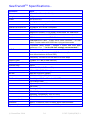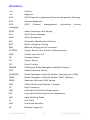
1
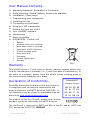
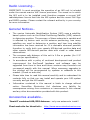
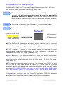
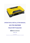
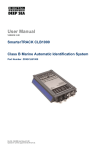
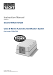
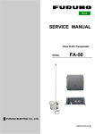
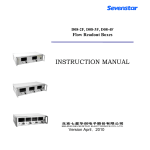
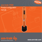
SeaTraceR TM S.287 Class B AIS Transponder (FCC ID: RIKS287) USER MANUAL SevenStar Electronics Ltd © SevenStar 2014 1 S.287-2/UM1/EN/3.1 About this manual… This manual contains details and recommendations for the programming, installation and use of the SeaTraceR S.287 Class B AIS Transponder from SevenStar Electronics Ltd. Please read through the installation notes carefully BEFORE attempting to connect power to the unit. The unit will need programming with your MMSI before it will be fully functional. Please note that incorrect installation or operation may void your warranty. Unpacking… The carton contains your SeaTraceR Class B AIS transponder with mounting bracket and integral power lead, this User Manual, a combined USB/NMEA0183 data cable and a CD-ROM containing programming software, an electronic copy of this manual and additional information. To install and operate the unit, you will also need a +12 or +24Vdc nominal power source, a VHF antenna and a GPS antenna (these should be separate from other antennae fitted to the vessel). Note: BEFORE installation, your vessel’s MMSI and other data needs to be entered into the unit. This may be performed using SevenStar’s ‘proAIS’ software, but note that for US territories the FCC have ruled that this must be done by an appropriately qualified person such as a suitably trained installer or dealer. Furthermore, it is a Federal offence to knowingly enter an unauthorised MMSI or false static data. (Please contact your dealer if you need assistance or advice.) Once programmed and installed, the SeaTraceR Class B AIS transponder will be able to automatically exchange MMSI, vessel name, position, call sign, course and speed data with other vessels and shore stations. Other suitably equipped vessels will be able to see your position clearly. Connect your SeaTraceR unit to your chart plotter or PC with the data cable provided to SEE the full benefits of AIS - you will then be able to see the ID, position, speed and course of all AIS equipped vessels in range! Please now take the time to read the rest of this manual to get the best from your Class B AIS Transponder. Please dispose of any unwanted packaging responsibly. © SevenStar 2014 2 S.287-2/UM1/EN/3.1 User Manual Contents… Warranty statement, Declaration of Conformity Radio Licensing, General Notices, Accessories available Installation…3 easy steps 1. Programming your transponder 2. Installing the unit 3. Connecting the SeaTraceR Using your AIS transponder Getting the most out of AIS Your 'proAIS2' software Maintenance About SevenStar APPENDICES - Further info Options Antenna choice and mounting What data is sent or received Description of LED indicators Trouble shooting guide More about AIS Standards Product Specification Glossary 2015 Warranty… This product carries a 2-year return-to-factory warranty against defects due to faulty manufacture or materials (i.e. 2 years from date of manufacture). In the event of a problem, please follow the simple trouble-shooting guide in this manual before contacting your dealer. Declaration of Conformity… SevenStar Electronics Ltd declares that this product is in compliance with the essential requirements and other provisions of the R&TTE directive 1995/5/EC. A full Declaration may be viewed or downloaded from our web site at www.sevenstarelectronics.com Intended EC country of use: GB AT NO IE FR NL BE LU ES PT IT GR SE DK FI CH The product carries the CE mark, notified body number and alert symbol as required by the R&TTE directive. The SeaTraceR is approved by BABT and BSH in the EU, and by USCG and FCC, and carries the FCC ID: RIKS287 © SevenStar 2014 3 S.287-2/UM1/EN/3.1 Radio Licensing… IMPORTANT: In most countries the operation of an AIS unit is included under the vessels marine VHF licence provisions. The vessel on to which the AIS unit is to be installed must therefore possess a current VHF radiotelephone licence that lists the AIS system and the vessel Call Sign and MMSI number. Please contact the relevant authority in your country for more information. General Notices… The marine Automatic Identification System (AIS) uses a satellitebased system such as the Global Positioning Satellite (GPS) network to determine position. The accuracy of these networks is variable and is affected by factors such as the antenna positioning, how many satellites are used to determine a position and how long satellite information has been received for. It is desirable wherever possible therefore to verify both your vessels AIS-derived position data and other vessels AIS-derived position data with visual or radar based observations. The compass safe distance of this unit is 0.5m or greater (for 0.3° error as per specification). In accordance with a policy of continual development and product improvement the SeaTraceR hardware and software may be upgraded from time to time and future versions may therefore not correspond exactly with this manual. When necessary upgrades to the product will be accompanied by updates or addenda to this manual. (Check on web site) Please take time to read this manual carefully and to understand its contents fully so that you can install and operate your AIS system correctly and get the full benefit. Information contained in this manual is liable to change without notice. SevenStar Electronics Ltd. disclaims any liability for consequences arising from omissions or inaccuracies in this manual and any other documentation provided with this product. Accessories available… 'Combi2' combined AIS/GPS Antenna - only one antenna to install! Check web site for latest info: © SevenStar 2014 http://www.sevenstarelectronics.com 4 S.287-2/UM1/EN/3.1 Installation…3 easy steps Installing the SeaTraceR is straightforward using simple tools, but you will need to check you have everything ready first. Step 1 The unit must be programmed with your MMSI, vessel name, size, etc. In US territories this must be done by a suitably qualified installer or dealer. The MMSI is usually listed on the vessel’s radio license. If you do not have one, you will need to apply for one – ask your dealer or Coastguard if in doubt. Step 2 Mount the unit safely, out of the way, in a protected place. Step 3 You have to connect up the unit – the connections are shown below SeaTraceR +12 or +24Vdc nom (Red/brown =+ve) Plotter and other NMEA equipment VHF antenna* NMEA0183/USB GPS antenna* a) The SeaTraceR comes with a 1metre supply lead for you to connect up to your vessel’s +12 or +24Vdc supply – it is strongly recommended that you fit an in-line fuse, 3A rated b) VHF antenna* – mount as high on the vessel as practical for best performance, clear from obstruction or other antennas, and must be fitted with a 50 ohm TNC plug. (See page 15) c) GPS antenna* – this must be an ACTIVE type (has a built-in amplifier with gain >20dB). Mount with a clear view of the sky, away from any possible sources of interference. Must be fitted with a 50 ohm TNC plug. (See page 16) d) To view the received vessel positions, etc, connect the NMEA Tx port on the unit to your chart plotter or laptop PC, which must be running software capable of reading and displaying AIS data, using the data cable provided. The NMEA0183 Rx port can be used to add other NMEA data into the stream going to the plotter using the in-built data mux. *Alternatively, you can use the 'Combi2' combined GPS/AIS antenna available from SevenStar, which makes installation even easier. © SevenStar 2014 5 S.287-2/UM1/EN/3.1 1. Programming the transponder… Before any AIS Class B Transponder will operate fully, you must program in a few very simple details about your vessel: Vessel name Call sign MMSI* Vessel Type (select from dropdown menu) Dimensions including position of GPS antenna (enter figures in the 4 boxes) Finally, you must click here to save your data to the SeaTraceR. Note: In US territories, the FCC has mandated that this data must be entered by a qualified professional person, and it is a Federal offence to knowingly enter false data. To program the SeaTraceR, you will need to run SevenStar’s 'proAIS2' programming software. Connect the unit to be programmed to a free USB port on your PC or laptop using the cable provided (see p10). (Note: You do NOT need to connect +12 or 24Vdc power to the unit during programming. If you need to extend the cable, use a standard serial cable extender.) Check the correct com port is selected on the PC, and click 'Connect' on the proAIS2 software. Follow the on-screen instructions on the PC, and enter the data as requested. *Note that once you confirm the MMSI, you will not be able to change it (just like DSC Class D radios). If you need to change it in the future, for a new vessel, it can be ‘unlocked’ (reset) by one of our distributors. The proAIS2 software can be used to read and change the other data and user-programmable options at any time if needed in the future. (See pages 13-14 for more information about the 'proAIS2' software, and p16 for details of 'Silent Mode' and other options which can be programmed.) Your dealer can also assist you with programming – just make sure you have your vessel information with you! And please complete all the data fields to get the most out of your new AIS transponder! © SevenStar 2014 6 S.287-2/UM1/EN/3.1 2. Mounting the unit… It is recommended that the unit is attached to a solid wooden, fibreglass or composite surface with >15mm long self-tapping screws or similar. Position the unit and the cables so that any water running down the wires drips off rather than collecting on the unit. Note: the bracket provided can be used to mount the unit in several orientations - simply unscrew the black knurled thumbscrews, and fit the bracket in the orientation that suits you. Once installed, you can think of the unit as a computer modem – you should have no need to check it regularly – so mount it out of the way where it will not be knocked or subject to excessive vibration, temperature, sunlight, fuel or water. It should be mounted at least 0.5m from any magnetic compass. It makes good sense to have the LEDs visible in case you do ever need to check the unit. CAUTION: The SeaTraceR unit is designed for operation in the temperature range -25 °C to +55 °C. Do not install (or use) the SeaTraceR unit in environments which exceed this range. CAUTION: Do not install the SeaTraceR unit in an environment where it can be subject to excessive exposure to water. CAUTION: The casing of the SeaTraceR unit is NOT isolated from the negative terminal of the supply and therefore it is recommended that the unit is not attached to metal parts of the vessel. (This avoids any potential ‘ground loop’ problems.) CAUTION: BE SURE TO USE THE CORRECT TOOLS AND SAFETY EQUIPMENT WHEN INSTALLING THE UNIT AND THE ANTENNAS. IF IN DOUBT, ASK A PROFESSIONAL TO INSTALL IT FOR YOU. © SevenStar 2014 7 S.287-2/UM1/EN/3.1 3. Connecting the SeaTraceR… WARNING: DO NOT connect the SeaTraceR unit to a mains (line) AC electrical supply, as an electric shock or fire hazard could result. CAUTION: Do not connect the SeaTraceR unit to a DC supply exceeding 31.2 V or reverse the supply polarity. Damage to the unit may result. VHF antenna: For best performance, use a VHF antenna that covers up to 162.025MHz – not all do! Mount as high on the vessel as practical for best performance, clear from obstruction or other antennas, and it must be fitted with a 50 ohm TNC plug. (These connectors were designed for use in marine environments, and provide a splash-proof connection when mated.) Adaptors are available for different connector types. See safety warning in Appendices about antenna positioning. GPS: The SeaTraceR unit requires a +5v-powered active GPS antenna, suitable for a marine environment, and the down lead will need to be terminated in a TNC 50 ohm plug. The SeaTraceR feeds +5v to the antenna automatically via the GPS antenna lead – you do not need a separate supply. Alternatively: SevenStar have developed a combined GPS/AIS antenna for use with its AIS products. This makes installation quick and easy. Ask for details on our Marine-quality 'Combi2' combo antenna! Data: In order to see the data from approaching vessels and aids to navigation, you need to display the messages the SeaTraceR receives and decodes. To do this you need to connect a chart plotter, laptop PC, tablet or other display device to the SeaTraceR data port (9 way male sub-D connector on the rear panel). To connect to a PC or similar device, use only the cable provided to connect to the PC USB port (See diagram on p10). To connect to a NMEA0183 instrument, use the NMEA0183/RS422 connections on the cable provided (connections are shown on p10). Note that the software in the display device must be configured for AIS operation AND must be able to receive the standard Class B operation NMEA sentences – most manufacturers are issuing free software upgrades for their units. And don't forget you can multiplex in other 4800 baud NMEA data using the NMEA Rx port - so you don't run out of ports on your plotter! © SevenStar 2014 8 S.287-2/UM1/EN/3.1 Power: Connect a 12 or 24V DC power source (9.6-31.2V) capable of supplying 2A peak to the DC power lead (brown/red = positive, black/blue=negative). IT IS STRONGLY RECOMMENDED THAT AN IN-LINE FUSE IS USED, RATING 3A. View of SeaTraceR rear panel Connector for active GPS Antenna (includes +5v feed) Connector for VHF antenna POWER 12-24v Power cable (Brown/red is +ve) Data and Programming Connector Plug grey connector into SeaTraceR Custom data cable detail External switch for Silent Mode or SRM function if required (Also check programming is set to correct mode) RED GREEN WHITE BLACK YELLOW BLUE Tx.A Tx.B NMEA data out at 38400 baud to plotter Rx.A Rx.B NMEA data in at 4800 baud from other instruments To USB port on laptop or PC © SevenStar 2014 9 S.287-2/UM1/EN/3.1 AIS Data Connection… There is a 9-way D-type male connector mounted on the rear panel of the SeaTraceR transponder. This connector is used initially to program the unit with your MMSI, vessel name and other vessel data, and then once the transponder is installed, to send data about other vessels to your plotter or PC software for display. Do NOT use a standard serial cable direct to a PC! The connector provides input/output of data in two different formats, USB and RS422/NMEA – either may be used. The pin connections are shown in the following diagram (as seen looking at the rear panel): 1 2 6 3 7 4 8 Data cable detail 5 9 SeaTraceR Data connector on rear panel of SeaTraceR PIN FUNCTION USB port NMEA/RS422 and optional connections* WIRE COLOUR YELLOW 1 NMEA0183 RX.A 2 NMEA0183 TX.A (AIS data out) 3 USB DM 4 *Silent mode/SRM -ve AND USBGND 5 *Silent mode/SRM +ve 6 NMEA0183 RX.B BLUE 7 NMEA0183 TX.B WHITE GREEN BLACK RED 8 USBDP - 9 USB VBUS - The cable can be extended if needed using a standard PC serial extension cable. The default baud rate of the AIS data is 38,400 Baud with 8 data bits, one stop bit and no parity. No handshaking is used. The data interface conforms to IEC 61162-1. If your NMEA device only has one Rx input pin, just connect either the 'Tx.A' or 'Tx.B' signal to it, and take the NMEA common to ground. © SevenStar 2014 10 S.287-2/UM1/EN/3.1 Using your new transponder… Switching on… When the +12/24V supply is switched on all four LEDs visible on the front panel of the unit will flash. The red green and blue LEDs will then go out, leaving the yellow LED flashing. All GPS receivers need to ‘lock’ onto the signals from at least 3 satellites before they can compute a position, so there is a delay before full operation is available - this process may take up to 30 minutes worst case if the GPS receiver is starting from ‘cold’ (no previous position information). When this has been achieved, there is a further delay until the unit transmits its first position report (message 18), whereupon the yellow LED will go out leaving just the green LED on indicating that the unit is now operating correctly. The blue & yellow LEDs will be on if the unit is put into 'Silent Mode'. SILENT MODE GREEN YELLOW RED BLUE LED Power & Status OK Unable to transmit Fault detected Silent Mode FUNCTION Your AIS Class B Transponder is now fully working! Your plotter or PC, if connected and set correctly, should now show you all AIS-equipped vessels within range (and remember, this includes all commercial vessels > 300 tonnes, which HAVE to fit AIS transponders, and AIS-equipped AtoNs and racons, as well as the growing numbers of leisure craft and work boats now fitting these units.) And of course, your position will also be shown on THEIR displays. © SevenStar 2014 11 S.287-2/UM1/EN/3.1 Getting the most from AIS… Some hints and useful advice: • • • • • • • • Switch it on! Your SeaTraceR consumes around 2 watts – less than a single nav light. Only switch it off when you are safely tied up in harbour. Keep it fully operational! – then other vessels, Coastguard or VTS (Vessel Traffic Services) in port areas will be able to call you if they see you running into danger. Read the manuals for your plotter or chart software to make sure you are displaying the AIS targets in the most useful way. It may be possible to filter what is shown to avoid too much clutter in crowded waterways – and make sure you are not using too large a range relative to your speed. AIS targets are usually shown as triangles giving position and heading. A vector may also be shown to indicate speed over ground so you can assess any collision risk. Aids to navigation (AtoNs) such as buoys, channel markers and lighthouses are being increasingly identified by AIS transmissions at regular intervals. Shore stations will also be capable of creating “virtual AtoNs” where a warning will appear on your chart in the appropriate position without there being a buoy physically in position. This is likely to be used for temporary situations such as wrecks, or buoys which are out of position. For maximum help in poor visibility, AIS should ideally be combined with radar. Radar can show passive targets such as debris or vessels not equipped with functioning AIS transmitters. AIS will help to identify targets acquired by radar plotting aids such as MARPA, which can give automatic warnings of close approach. Always plan to keep a safe margin to avoid close quarters situations – at least 0.5nm closest point of approach (CPA), and more for vessels restricted in ability to manoeuvre. Aids such as AIS and MARPA can give a false sense of security; so don’t forget to use the 'Mk.1 Eyeball' to confirm the situation and to navigate according to the Collision Regulations. The Collision Regulations are not negotiable, but if you are uncertain of another vessel’s intentions and they have an AIS transmitter, then you will be able to readily call them on as you have their call-sign and vessel name. © SevenStar 2014 12 S.287-2/UM1/EN/3.1 'proAIS2' software… If you have been provided with a CD-ROM with your SeaTraceR, it contains a 'soft' copy of this manual, plus some interesting and informative software called 'proAIS2'. In order to use it, load the software onto your PC, then connect your SeaTraceR to your PC using the custom 9-way cable provided to a suitable USB port. Connect +12/24v power to the SeaTraceR, start the 'proAIS' software, make sure the correct port on your PC is selected, and then click the 'Connect' button. (Note: for programming use only you do not need to connect the SeaTraceR to a power supply - but it will not function as a full AIS Transceiver until you do!) proAIS2 allows you to program your vessel data into the Transponder, (this has to be done by a dealer or other competent person in USA), and also select some user options (see p16). It also offers you a number of ways of looking at the AIS data being processed by your SeaTraceR Transponder, and also at the operation of the integral GPS receiver. There are a number of pages arranged as 'tabs' across the top of the page. Configuration: This page displays the static data relating to the vessel, including the MMSI which must be programmed before the unit will function as a two-way transponder, and also some user-programmable options. See page 6 of this manual, and p16. GNSS Status: This tab shows the status of the internal GPS receiver, and includes the current position fix, course and speed as well as bar graphs of the strength of the GPS satellite signals being received. This can be used to verify correct GPS antenna connection and operation. © SevenStar 2014 13 S.287-2/UM1/EN/3.1 Other vessels: This page displays messages received from other vessels transmitting AIS data in your vicinity. MMSI, vessel name and call sign is displayed, along with speed, course, and latitude and longitude. An estimate of each vessels distance from you is also given. Diagnostics: This tab shows the internal condition of the SeaTraceR. It includes the information used to drive the LED's on the unit front panel, software version numbers, internal power supply measurements, and some statistics on numbers of messages received on each of the two AIS VHF channels. When you turn on you will see the conditions change as GPS lock is achieved, and messages are received and transmitted. Serial data: This page displays the raw NMEA0183 serial data being processed by the SeaTraceR. There is a facility to create a log file where received NMEA data can be logged. © SevenStar 2014 14 S.287-2/UM1/EN/3.1 Maintenance… The SeaTraceR unit is sealed against ingress of water or dust to IP-65. There are no user-serviceable parts inside, and the unit is protected against tampering, so DO NOT ATTEMPT TO OPEN THE UNIT. No regular maintenance is required other than wiping down with a soft cloth as necessary, and keeping the connectors in good condition. WARNING: Unauthorised opening of the SeaTraceR unit, or use outside recommended conditions, will invalidate the warranty. CAUTION: Avoid using chemical solvents to clean the SeaTraceR as some solvents can damage the case or label material. NOTE: The SeaTraceR unit contains no user serviceable parts. Contact your Service Agent for repair if necessary. About SevenStar… SevenStar was created in 2002 by committed, professional engineers with extensive experience in the design, manufacture, sales and marketing of marine safety electronic apparatus and other high tech communications equipment. SevenStar’s S.701 SART (Search And Rescue Transponder) set new standards in marine electronics, and its innovative digital design enabled it to be the first to be shipped globally as non-hazardous cargo. It is EU ‘Wheelmark’ and FCC approved, and it has since captured around 75% share of the latest market segments. SevenStar also designs bespoke transponders for both marine and airborne use. The SeaTraceR Class B AIS transceiver uses the latest digitally-defined radio techniques to achieve and exceed the demanding IEC AIS Class B specification released during 2006. The robust, IP-65 rated, powdercoated aluminium enclosure and versatile stainless steel mounting bracket have been designed to service both the professional vessel market and the safety-conscious leisure user equally. SevenStar is approved and audited annually to ISO 9001:2008. Its GMDSS/SOLAS products are 'Wheelmark' approved and the company is audited annually by Bureau Veritas. © SevenStar 2014 15 S.287-2/UM1/EN/3.1 APPENDICES List of Appendices… • • • • • • • • • • Options Warnings Antennas and antenna mounting What serial data is sent or received Description of LED indicators Trouble shooting guide More about AIS Standards SeaTraceR Specifications Glossary Options… * Silent Mode: If your business depends on temporary periods of ‘position reporting silence’, it is possible to fit a switch to your vessel that will temporarily disable the Transmit function of the SeaTraceR (called 'Silent Mode'). An external switch will need to be wired to the red and black wires in the customer data cable supplied (pins 4 and 5 of the SeaTraceR data connector) - see wiring connections on p10 of this manual. It must be stressed that this compromises the safety of your vessel and other vessels, and must NOT be done without careful consideration. * Blue LED function: the blue LED is used to indicate that the unit has been put into 'Silent Mode' and will not report your ID and position. * GPS Reporting Rate: The rate at which your vessels GPS position is sent to your plotter can be set during programming if required. * Non-active Alarm Reporting: Non-active alarm messages are suppressed by default, but can be selected if required. © SevenStar 2014 16 S.287-2/UM1/EN/3.1 Warnings… VHF Antenna Connection… Connecting a badly mismatched VHF antenna, leaving the VHF antenna port disconnected, using a poor quality or poorly jointed cable, or shorting the VHF antenna port will activate the internal VSWR alarm (red LED will be lit), causing the unit to stop sending position reports, and may cause damage to the transponder. Radio Frequency Exposure… This equipment generates and radiates radio frequency electromagnetic energy and, if not installed and used in accordance with the instructions, may cause harmful interference or even personal injury. Never switch on the equipment without the VHF antenna properly connected. To maximise performance, and minimise human exposure to RF energy, always mount the antenna at least 1.5 meters from the transponder. This system has a Maximum Permissible Exposure (MPE) radius of 1.5m, assuming max antenna gain of +3dbi. Use of higher gain antennas would require a greater MPE radius and is not recommended. The VHF antenna should be mounted at a minimum vertical distance of 3 metres from the head of any person standing on deck in order to meet international safety directives on Maximum Permissible Exposure (MPE) / Specific Absorption Rate (SAR). Failure to adhere to these limits could expose persons within the 3 metre radius to RF radiation in excess of the recommended MPE / SAR limits. Antennas and Antenna Mounting… VHF antenna for AIS use… The VHF antenna employed for AIS use: ¾ Must be suitable for marine shipboard applications (index of protection, ruggedness, means of mounting, etc.) ¾ Should be omni-directional and vertically polarised with a bandwidth sufficient to maintain VSWR <1.5 over the frequency range 156 – 163 MHz. As a minimum the -3dB bandwidth must cover the two AIS channels and the DSC Channel. © SevenStar 2014 17 S.287-2/UM1/EN/3.1 ¾ Should ideally be a dedicated antenna, i.e. not shared with any other VHF transmitter/receiver. ¾ Should ideally be mounted with at least a two metre vertical separation distance from any other VHF antenna used for speech or DSC communication but see also the section “Radio Frequency Exposure” Warning above. GPS Antenna… The GPS antenna used must be of the active type (i.e. it should incorporate a low noise amplifier) and must be suitable for marine shipboard applications (index of protection, ruggedness, means of mounting, etc.). It must be capable of running from the +5v that is fed up the GPS coax cable. Most +5v active GPS antennas will work well with the SeaTraceR on short to medium cable lengths. If you need to use long cables then you may need to select an antenna with a higher gain (in dB) to deliver an acceptable signal level to the SeaTraceR GPS antenna connector. (Antenna gain - cable loss should be more than approx 15dB.) The GPS antenna to be used for AIS use must be a dedicated antenna, i.e. not shared with any other GPS receiver. Installation of the GPS antenna is critical for the performance of the built -in GPS receiver that is used for correct timing of the transmitted data, and also for the supply of navigational information should the main navigational GPS fail. We strongly recommend that: • The GPS antenna is mounted in a slightly elevated position and free of shadow effect from the ship’s superstructure • The GPS antenna has a free view through 360 degrees with a vertical angle of 5 to 90 degrees above the horizon. • As the received GPS signal is very sensitive to noise and interference generated by other onboard transmitters, ensure that the GPS antenna is placed as far away as possible from radar, Inmarsat and Iridium transmitters and ensure the GPS antenna is free from direct view of the radar and the Inmarsat beam. • It is also important that any MF/HF and other VHF transmitter antennas are kept as far away as possible from the GPS antenna. Try to keep the GPS antenna at least 3 meters away from these antennas. © SevenStar 2014 18 S.287-2/UM1/EN/3.1 What data is sent or received… As mentioned above, the data port is used for programming the unit as well as for ‘passing on’ the AIS data received from other vessels, AtoNs and shore stations. Note: Either USB or NMEA0183 (RS422) connections may be used. USB is intended for connection to PC USB ports and similar devices. RS422 is a 'balanced' wiring system, in which +ve and –ve signals are used to give good immunity to noise. These can be used to connect to NMEA ports on plotters, etc. (It is allowable in many cases to just use one of the two connections and ground (0v), but this will be more susceptible to electrical noise.) Data/message types vary with the activity: a) During programming, the data/message types are proprietary to the SeaTraceR. b) Power up messages: On power up the unit will report details of the firmware versions residing in the unit. c) In normal AIS transponder operation, each message received over the VHF Data Link (VDL) is decoded and relayed on to the display unit as a VHF Data Link Message (VDM). d) Also as part of normal operation, the SeaTraceR’s VHF data link own vessel messages (VDO) transmitted over the VDL are also sent to the display unit. e) GPS own-position reporting messages - the frequency of these can be programmed if required f) AIS regional channel assignment messages (ACA) received. These are derived from an incoming VHF Data Link message (message 22) or from a DSC message. g) AIS channel management information source (ACS) messages. h) Alarm messages (ALR, TXT) can be sent to the display unit and Alarm acknowledgement messages (ACK) received from it. Many internal checks are performed and it is possible to suppress all but active alarms. i) It is possible to modify the behaviour of the SeaTraceR slightly under switch control – see ‘Options’ section. (VDM, VDO, ACA, GPS, ACS, ALR, TXT and ACK messages conform to NMEA 0183. Please refer to NMEA 0183 for full details of these AIS messages.) © SevenStar 2014 19 S.287-2/UM1/EN/3.1 Description of LED Indicators… Status – GREEN (‘All OK’) This green LED indicates, when lit, that power has been connected correctly to the transponder, that the transponder has been configured with a valid MMSI, that the operating software is present and running, that GPS lock has been acquired and position data transmitted, and that the AIS antenna port appears to be connected correctly. TX Timeout – YELLOW (‘Waiting for GPS lock/Unable to Tx') The yellow LED flashes when first switched on to indicate that the unit is waiting to acquire GPS lock. This yellow LED indicates, when lit, that the SeaTraceR transmitter is currently prevented from transmitting. If the unit has not been able to transmit a position report during the last expected two reporting intervals, either because of loss of GPS lock, lack of a valid MMSI, or for operational reasons such as a Message 23 quiet period, high channel load conditions, etc, the yellow LED will illuminate. It will also illuminate if the user has chosen to use the ‘Silent Mode’ option. This is a warning condition only and indicates that your vessels position is not currently being reported to other vessels. Reception of other vessel AIS information by the SeaTraceR is not affected. When the unit is able to commence reporting again the yellow LED goes out. Error - RED (‘Fault condition exists’) This red LED indicates, when lit, one of the following status conditions: • Unit does not have a valid MMSI • Transmitter lockout timer (1 second max) has operated • GPS is unable to gain lock even after 30 minutes • VHF antenna VSWR is out of range (poor connection, badly sited antenna) • Power Supply is out of range • Background noise level is above the threshold level (-77dBm) (Poor connection and/or poor antenna siting.) Silent Mode - BLUE (‘Silent Mode has been selected’) If the Silent Mode option is invoked, the blue LED is lit continuously to indicate that the unit is in Silent Mode. Your position and ID will not be transmitted to other vessels or receiving stations. The yellow LED will also be on. © SevenStar 2014 20 S.287-2/UM1/EN/3.1 Trouble-shooting guide… With all electronic equipment, unexpected or severe transient conditions may leave the equipment in a ‘locked-up’ state. Every effort has been made to prevent this occurring with the SeaTraceR. If you think this may be the case, simply disconnect (switch off) the power connection, leave for a few minutes, and then reconnect the power. If you have reason to think your transponder is not working correctly, check the following before contacting your technician or dealer: Unit shows no LEDs lit, sends no data for display: ¾ Faulty power connection or in-line fuse blown ………Unit should operate normally when fault is fixed Unit powers up but yellow LED comes on: ¾ Unit has not been configured/programmed with a valid MMSI ¾ Poor or broken GPS antenna connection, poor GPS antenna position ¾ GPS signal blocked, either physically, or by excessive electrical noise ¾ Shore station has requested Class B silent mode ¾ Heavy local AIS traffic has blocked your AIS transmission ………Unit should recover when the condition is removed. Unit powers up but red LED comes on: ¾ Unit has not been configured/programmed with a valid MMSI ¾ Poor or broken VHF antenna connection, poor antenna position ¾ Interrupted or out of range power connection ¾ GPS has been unable to lock on even after 30 minutes ………Unit should recover when the condition is removed. If the Red LED illuminates continuously even after correcting these items, the unit should be switched off for a few minutes, then tried again. If the fault persists it can be assumed to be faulty and should be switched off (power removed). Consult your dealer or technician. Unit powers up with just green LED on, but no data is displayed: ¾ Poor or incorrect data cable connection to plotter or PC ¾ Plotter or PC not configured or not able to receive AIS sentences Other vessels report they can't see my vessel name or call sign: ¾ This data is not transmitted as often as the MMSI, etc, so it can take a little while to appear on screen (up to 6 minutes or even longer). Also, this data message was only introduced in 2006 so older receiving equipment will need updating to receive/display it correctly. © SevenStar 2014 21 S.287-2/UM1/EN/3.1 More about AIS… The marine Automatic Identification System (AIS) is a location and vessel information reporting system. It allows vessels equipped with AIS to automatically and dynamically share and regularly update their position, speed, course and other information such as vessel identity with similarly equipped craft and with shore stations. Position information is derived from a Global Navigation Satellite System (GNSS) such as GPS, and communication between vessels or between vessel and shore is by VHF digital transmissions on channel 87B at 161.975MHz, or on channel 88B at 162.025MHz. The system can cope with large numbers of vessels in close proximity because a sophisticated and automatic method of time sharing the radio channel is used to ensure that blocking of individual transmissions is minimised, and any potential degradation of the expected position reporting interval is indicated to the user. If the unit suffers extreme channel overload conditions it will always recover to normal operation. AIS Classes… There are two classes of AIS unit fitted to vessels, Class A and Class B. In addition AIS base stations may be employed by the Coastguard, port authorities and other authorised bodies. AIS units acting as aids to navigation (AtoNs) can also be fitted to fixed and floating navigation markers such as channel markers and buoys. Class A units are a mandatory fit under the safety of life at sea (SOLAS) convention to vessels above 300 gross tons or which carry more than 11 passengers in International waters. Many other commercial vessels and some leisure craft also fit Class A units. Class B units are now becoming mandatory fit in several countries as they look to improve their security and safety. Class B units are designed for fitting in vessels which do not fall into the mandatory Class A fit category. The SeaTraceR is a Class B unit. Information Transmitted and Received… Class A units transmit their IMO number (if known), MMSI, Call sign and Name, length and beam, ship type, time, course over ground (COG), speed over ground (SOG), heading, navigational status, rate of turn, draught, cargo type, destination and safety related messages via a short message service (SMS) facility. Message lengths are variable with static © SevenStar 2014 22 S.287-2/UM1/EN/3.1 and voyage related information being transmitted less often. Class B units transmit their MMSI, Call Sign and Name, length and beam, ship type, time, course over ground (COG), speed over ground (SOG) and heading. Standards… This product complies with all the necessary standards under the European R&TTE directive for Article 3.1(a), 3.1(b), 3.2 and 3.3(e). The following standards have been followed in pursuance of this: • IEC62287-1: 2006-03 Maritime navigation and radiocommunication equipment and systems – Class B shipborne equipment of the automatic identification system (AIS) – Part 1: Carrier-sense time division multiple access (CSTDMA) techniques • IEC60945: 2002-08 Maritime navigation and radiocommunication equipment and systems – General requirements – Methods of testing and required test results • IEC61162-1: Maritime navigation and radiocommunication equipment and systems – Digital interfaces – Part 1: Single talker and multiple listeners • IEC61108-1: GLOBAL NAVIGATION SATELLITE SYSTEMS (GNSS) – Part 1: Global positioning system (GPS) —Receiver equipment — Performance standards, methods of testing and required test results • EN 301 843-1 v2.1: Electromagnetic compatibility and Radio spectrum Matters (ERM); Electromagnetic Compatibility (EMC) standard for marine radio equipment and services; Part 1: Common technical requirements • EN 50383: 2002 Basic standard for calculation and measurement of electromagnetic field strength and SAR related to human exposure from radio base stations and fixed terminal stations for wireless telecommunications system (110MHz – 40GHz) • EN60950-1: 2001 Information technology equipment – Safety – Part 1: General requirements © SevenStar 2014 23 S.287-2/UM1/EN/3.1 SeaTraceRTM Specifications… Parameter Value Dimensions 180 x 110 x 40 mm (L x W x H) Weight 900g Power DC (9.6-31.2V) Average power consumption 2W Peak current rating 2A Internal GPS Receiver 50 channel, IEC 61108-1 compliant Electrical Interfaces USB 2.0 Connectors VHF Antenna connector - TNC 50 ohm coaxial - on rear panel NMEA0183 (RS422) Tx (to plotter):38,400 baud, Rx: 4800 baud GPS Antenna connector - TNC 50 ohm coaxial - on rear panel USB/NMEA0183 data - 9-way sub-D male connector - on rear panel. Custom cable with USB male A plug and bare ends. +12-24Vdc (nom) Power - Integral 1 metre twin core lead, red/brown =+ve. ***In-line 3A fuse strongly recommended*** VHF Transceiver Transmitter - single channel 2 Independent, simultaneous VHF Receivers time shared between AIS and DSC) (One of which is Frequency: 156.025 to 162.025 MHz in 25 kHz steps Output Power +33dBm ± 1.5 dB (2 watts nominal) Channel Bandwidth 25kHz Channel Step 25kHz Modulation Modes 25kHz GMSK (AIS, TX and RX) Bit rate 9600 b/s ± 50 ppm (GMSK) RX Sensitivity Sensitivity - 107dBm 25kHz for 20% PER 25kHz AFSK (DSC, RX only) 1200 b/s ± 30 ppm (FSK) Co-Channel 10dB Adjacent Channel 70dB IMD 65dB Blocking 84dB Environmental IEC 60945 (protected) Operating Temperature: -25ºC to +55ºC IEC 62287, Section 5, Cat b) protected from the weather Compass safe distance 0.5 metre Indicators Status, TX timeout, Error, Rx Data, Silent mode activated Operator options 'Silent mode', baud rate, error & GPS report rates © SevenStar 2014 24 S.287-2/UM1/EN/3.1 Glossary… +ve Positive -ve Negative ACA (AIS) Regional Assignment Channel Assignment Message ACK Acknowledgement ACS (AIS) Channel management information source messages AFSK Audio frequency-shift keying ALR (AIS) Alarm Message AtoN Aid to Navigation AIS Automatic Identification System BIIT Built In Integrity Testing BNC Bayonet fitting type RF connector CSTDMA Carrier Sense Time Division Multiple Access COG Course over Ground CR Carriage Return CS Carrier Sense DC Direct Current DGNSS Differential Global Navigation Satellite System DSC Digital Selective calling GLONASS Global Navigation Satellite System (alternative to GPS) GNSS Global Navigation Satellite System (GPS, Glonass) GMSK Gaussian Minimum Shift Keying GPS Global Positioning Satellite / System HF High Frequency IMO International Maritime Organization IEC International Electrotechnical Commission LED Light Emitting Diode LF Line Feed LNA Low-noise amplifier MF Medium Frequency © SevenStar 2014 25 S.287-2/UM1/EN/3.1 MKD Minimum Keypad and Display MMSI Maritime Mobile Service Identity MPE Maximum Permissible Exposure NMEA National Marine Electronics Association PC Personal Computer PI Presentation Interface RF Radio Frequency RTCM Radio Technical Commission for Maritime Services RX Receive or Receiver RFI Radio frequency interference SAR Specific Absorption Rate SMS Short Message System SOG Speed over Ground SRM Safety Related Message TDMA Time-division Multiple Access TNC Threaded type coaxial connector TX Transmit or transmitter UTC Universal Time Co-ordinated VDM (AIS) VHF Data Link Messages VDO (AIS) VHF data link own vessel messages VHF Very High Frequency VSWR Voltage Standing Wave Ratio Please Note… The latest version of this manual is available in the Downloads section of our website, along with further information which may be of interest. http://www.sevenstarelectronics.com SevenStar Electronics Ltd © SevenStar 2014 26 S.287-2/UM1/EN/3.1 SeaTraceR S.287-2 User Manual - ERRATA Please note that the blue LED on the front panel may be labelled Data Rx because some options on certain software versions flash it to indicate that an AIS data message has just been received. As the manual explains, it is also more commonly used to indicate that the unit has been put into 'Silent Mode' and will not transmit your position. SevenStar Electronics Ltd © SevenStar 2014 27 S.287-2/UM1/EN/3.1