1
SERVICE INSTRUCTIONS FOR
Fire Alarm System
FX
Version 2.3
2006-09-27
Jari Ollila
Hannu Salo
Oy Esmi Ab
Copyright (c) Oy Esmi Ab, 1994 .. 2006
The copyright to the documentation herein is the property of Oy ESMI Ab, Espoo, Finland. The
contents may be used and / or copied only with the written permission from ESMI or in accordance
with the terms and conditions stipulated in the agreement / contract under which the documentation
has been supplied.
F:\FX\CUSTOMER\SERV\FX SERVICE INSTRUCTIONS v. 2.3.doc
2 (21)
CONTENTS
1.
2.
3.
4.
5.
6.
7.
8.
9.
10.
VERSIONS OF THIS DOCUMENT........................................................................................ 3
BLOCK DIAGRAM OF THE CONTROL PANEL ............................................................... 4
MONITORINGS (FAULT EXPLANATIONS) ...................................................................... 5
PROGRAM MONITORING (SYSTEM FAULT)................................................................ 15
ACCESS LEVEL 3 (SERVICE STATE) AND 4................................................................... 15
SETTINGS ON THE COMPONENT BOARDS................................................................... 16
PC CONFIGURATION ........................................................................................................... 18
TO UPDATE THE APPLICATION PROGRAM IN THE UNITS .................................... 20
RESTARTING THE SYSTEM ............................................................................................... 20
BOARD REPLACEMENT .................................................................................................. 20
3 (21)
1.
VERSIONS OF THIS DOCUMENT
Version
0.15
1.1
1.2
1.3
1.7
Date
By
20.08.2005
27.10.2005
27.10.2005
20.03.2006
IN
TB
TB
HJS
2.0
09.05.2006
TB
2.1
2.2
2.3
31.05.2006
11.07.2006
27.07.2006
IN
SS
HJS
Modification
Initial document as supplied to the test house
New fault codes added (12, 66, 92, 93, 94)
Clean up of old changes, minor editorial changes
Rewriting of access levels chapter
Intellia Loop Controller ALC added
PSA monitoring and fuses added
CLC line monitoring added
All changes of previous versions up until temporary version 17
accepted (tracking of changes stopped)
Document released as version 2.0
Fault and maintenance codes of address points updated
MC flash erase procedure added
ALC loop cable resistance specification modified
4 (21)
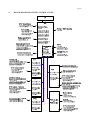
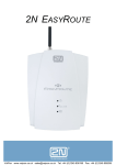
2.
BLOCK DIAGRAM OF THE CONTROL PANEL
5 (21)
3.
MONITORINGS (FAULT EXPLANATIONS)
All fault warnings are indicated on the display with an optical and an audible signal. Fault warning origins
are specified, either by means of a monitor specific LED, or by means of a fault explanation, displayed on
the alphanumeric display.
To clarify the reason for a fault warning, first:
− silence the common fault warning
− disable the monitoring of the faulty object
− reset the fault warning condition,
then:
− select the faulty object
− set it to test state.
3.1.
MONITORING OF DETECTION CIRCUITS
3.1.1. Loop Controller (LC)
A detection circuit of the FX control panel is a closed loop. That means, the loop starts at and returns to the
Loop Controller (LC). A single break in the loop cable doesn't prevent the communication in the loop.
The start point of the loop is connected to the terminals A+ and A- and the end point of the loop is connected
to the terminals B+ and BThe communication between loop devices and loop controller is accomplished by using serial
communication. (The loop devices includes sensors and other addressable modules installed to the loop.) The
loop controller sends the address and command bits. The loop devices response with current pulses. The
information is represented by the lengths (time) of these pulses.
The break monitoring circuit is on the LC. The voltage level between terminals B+ and B- is monitored.
Short circuit isolators are provided on the loop controller, both in the start point and in the end point of the
loop.
Maximum cable resistance of the loop is 40 ohms and capacitance between the loop wires is 360 nF.
3.1.1.1. Normal Condition
Normally the voltage between terminal A+ and A- (on the loop controller) is approx. 24 V (when the mains
is on). During communication the voltage of the loop varies between 24 V and 5V and 0 V.
3.1.1.2. Fire Condition
If fire is detected, there is no change in the loop voltage compared to the normal condition (only current
consumption is increased because of alarm led of detector).
3.1.1.3. Loop Break Condition
Cable resistance of loop has radically increased so that depending on the load the voltage over B+ and B- is
lower than 14 V. After a loop break detection the second loop relay is activated and the loop is supplied also
from the end point (terminals B+ and B-).
Monitoring:
Dc voltage level between B+ and B- is lower than approx. 14 V.
6 (21)
3.1.1.4. Short Circuit Condition
If the loop voltage falls below the fault limit, the supply of the loop is cut and after a new start up the isolator
circuit can separate the faulty part of the loop if at least one isolator is installed in the loop.
Monitoring:
The loop current is limited to approx. 560 mA. If the loop voltage measured between A+ and A- is decreased
more than 5 V comparing the normal loop voltage the short circuit is detected.
3.1.2. Intellia Loop Controller (ALC)
A detection circuit of the FX control panel is a closed loop. That means, the loop starts at and returns to the
Intellia Loop Controller (ALC). A single break in the loop cable doesn't prevent the communication in the
loop.
The start point of the loop is connected to the terminals A+ and A- and the end point of the loop is connected
to the terminals B+ and BThe communication between loop devices and loop controller is accomplished by using serial
communication. (The loop devices includes sensors and other addressable modules installed to the loop.) The
loop controller sends the address and command bits. The loop devices response with current pulses.
The break monitoring circuit is on the ALC. The voltage level between terminals B+ and B- is monitored.
Short circuit isolators are provided on the loop controller, both in the start point and in the end point of the
loop.
Maximum cable resistance of the loop is 60 ohms and capacitance between the loop wires is 500 nF.
Maximum cable resistance between panel and first short circuit isolator and between two short circuit
isolators is 15 ohms.
3.1.2.1. Normal Condition
Normally the voltage between terminal A+ and A- (on the loop controller) is approx. 27,2 V. During
communication the voltage of the loop varies between 27.2 V and 35V.
3.1.2.2. Fire Condition
If fire is detected, there is no change in the loop voltage compared to the normal condition (only current
consumption is increased because of alarm led of detector).
3.1.2.3. Loop Break Condition
Cable resistance of loop has radically increased so that depending on the load the voltag over B+ and B- is
lower than 14 V. After a loop break detection the second loop relay is activated and the loop is supplied also
from the end point (terminals B+ and B-).
Monitoring:
Dc voltage level between B+ and B- is lower than approx. 14 V.
7 (21)
3.1.2.4. Short Circuit Condition
If the loop voltage falls below the fault limit, the supply of the loop is cut and after a new start up the isolator
circuit can separate the faulty part of the loop if at least one isolator is installed in the loop.
Monitoring:
The loop current is limited to approx. 560 mA. If the loop voltage measured between A+ and A- is less than
25 V the short circuit is detected.
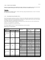
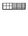
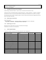
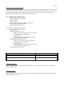
3.1.3. Conventional Loop Controller (CLC)
The FX panel handles internally the whole CLC board as one addressable loop and each conventional line as
an address of that loop. Each conventional line can therefore be configured and used just as the conventional
zone module connected to an addressable detection circuit.
It also means that the conventional lines are handled by the user in the same way as the conventional zone
modules, e.g. for disablement/re-enablement.
Each line is by default in its own detection zone.
The voltage supplied by the CLC to the conventional line is 21Vdc to 24Vdc.
Monitoring of conventional line:
Configuration
Type
Condition
End of line
Exi-area
Fault (open circuit)
Conventional
line
Conventional
line
Conventional
line
Conventional
line
Input line
4k7
4k7
2k94
2k94
4k7
no
yes
no
yes
no
Voltage (V) over
measuring resistor
(R200 – 215)
Current (mA)
in line
0- 0,5
0 – 1,8
Normal
0,9 – 1,65
4,0 – 6,8
Alarm
2,05 – 13,75
9,5 – 59,4
Fault (short circuit)
14,21 - 24
67,9 – 144,8
Fault (open circuit)
0 – 0,43
0 -1,5
Normal
0,81 – 1,43
3,6 – 5,9
Alarm
1,85 – 5,96
8,6 – 25,5
Fault (short circuit)
6,37 – 9,18
30,3 – 39,5
Fault (open circuit)
0-1
0 – 4,0
Normal
1,4 – 2,69
6,4 – 11,3
Alarm
3,11 – 13,75
14,6 – 59,4
Fault (short circuit)
14,21 - 24
67,9 – 114,8
Fault (open circuit)
0 – 0,82
0 – 3,2
Normal
1,21 – 2,17
5,5 – 9,1
Alarm
2,57 – 5,96
12,0 – 25,5
Fault (short circuit)
6,37 – 9,18
30,3 – 39,5
Fault (open circuit)
0- 0,31
0 - 1,0
8 (21)
Input line
4k7
yes
Normal
0,67 – 1,32
2,9 – 5,4
Alarm
1,7 – 4,67
7,8 – 19,9
Fault (short circuit)
5,1 - 24
24,2 – 114,8
Fault (open circuit)
0 – 0,31
0 – 1,0
Normal
0,67 – 1,23
2,9 – 5,0
Alarm
1,59 – 4,67
7,3 – 19,9
Fault (short circuit)
5,1 – 9,18
24,2 – 39,5
9 (21)
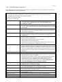
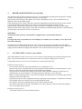
3.1.4. Fault Monitoring of Loop Devices
Fault and maintenance warnings of the loop devices are identified by codes in the display. The codes and a
short explanations of each are listed below.
Fault and maintenance warnings of address point
s = start up phase when scanning devices (after panel (re)start or when is loop connected by user)
r = runnning time when device id normally monitored
c = loop is confugured with PC
n = loop is not configured
− The anytype of device has been configured for this address but no device
is installed. This is indicated only once and will disappear after
resetting the warning
MAINTENANCE 01: (s,c) − No device has been configured to this address but some device is
installed. This is indicated only once and will disappear after resetting
the warning
MAINTENANCE 02: (s,c) − Definite type of device has been configured but no device is installed.
This warning can be removed only by installing device to this address or
changing the configuration.
MAINTENANCE 03: (s,c) − The configured type and installed type is not the same. This warning can
be removed only by changing device to this address or changing the
configuration.
MAINTENANCE 04: (s,n) − A module and a detector has the same address switch setting. This is not
allowed without configuration.
− Module data will replace detector data in memory.
− Warning will be re-created after reset.
− Addresses have to be fixed and either the panel has to be restarted or the
loop has to be disabled and re-enabled in service state.
MAINTENANCE 05: (s,n) − Factory setting of address switches are 0,0. When panel starts or a
previously disabled loop is re-enabled, detector(s) and module(s) with 0,0
address value are indicated maintenance warning. The LED’s of the
detector or module blink automatically for easier identification. It is not
possible to detect any other fault or fire conditions for units that has the
00 address.
FAULT 06: (s,c/n)
− Unknown type of device.
FAULT 07: (s,n)
− Device removed from this address during loop disablement. The fault is
detected when the loop is re-enabled.
− Disablement of an address with this fault is not possible because the data
of the unit will be removed from memory when the fault is reset. If
disabled before the loop enablement, the disablement will also be
removed automatically when the fault is reset. This is indicated only
once and will disappear after resetting the warning
FAULT 08: (s,n)
− The type of device is changed. This is indicated only once and will
disappear after resetting the warning
FAULT 09: (s,n)
− New addresses (devices) are found in the loop. This is indicated only
once and will disappear after resetting the warning
MAINTENANCE 11: (s,c) − Siren control (separate remote LED control) have been configured for
sensor but the feature not exist in sensor
FAULT 12: (s,c)
− Technical alarm input configured for LC address but SW version of LC is
not compatible (> 1.3)
FAULT 13: (s,c/n)
− Two or more devices have the same address ("double address”).
MAINTENANCE 14:(s,c/n) − Bad scan responses of a device.
MAINTENANCE 15:(s,c/n) − Frame type ID is not compatible with memory type ID
MAINTENANCE 00: (s,c)
10 (21)
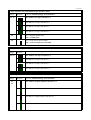
MAINTENANCE 16: (s,c)
FAULT 51: (r)
FAULT 52: (r)
FAULT 53: (r)
FAULT 54: (r)
FAULT 55: (r)
FAULT 56: (r)
FAULT 57: (r)
FAULT 58: (r)
MAITENANCE 59: (r)
MAINTENANCE 60: (r)
FAULT 62: (r)
FAULT 63: (r)
FAULT 64: (r)
FAULT 65: (r)
FAULT 66: (r)
FAULT 70: (r)
FAULT 71: (r)
FAULT 72: (r)
FAULT 73: (r)
FAULT 74: (r)
FAULT 75: (r)
FAULT 76: (r)
FAULT 77: (r)
FAULT 78: (r)
− Protocol family of device and configuration mismatc
−
− Too low analog value ( < 400 us ) received from analog sensor
− Fault in the internal operation of an OMNI / 2251TEM / 7251LASER
sensor
− Invalid reply from the address.
− Two or more devices have the same address ("double address”).
− Break in the input circuit of a monitor module.
− Break in the output circuit of a control module.
− Short circuit in output circuit of a control module.
− Input module has been configured as "fault input". When module alarms
FX show it as fault warning.
− Input module has been configured as "zone disablement device" and
disablement time exceeds (default 12h).
− Input module is configured as "maintenance input". When module
alarms FX show it as maintenance warning.
− A dirty detector. If the analog value of the detector has exceeded the
maintenance limit for more than 24 hours, this warning is indicated.
− If detector exceeds value (during 24h) after user reset this fault warning,
fault warning is re-generated immediatelly.
− Also at case that value of some other detector(s) stay over the
maintenance limit (but 24h timeout has not expired) at the moment when
user select from the menu “report dirty detector” and press “enable” at
access level 3, this fault warning is created.
− OMNI / 2251TEM / 7251LASER drift compensation alert
− OMNI / 2251TEM >200 <560; 7251LASER >200 < 650
− Break or short circuit at the conventional sub loop of conventional zone
module.
− Invalid response from detector (> 4000 µs for normal sensors, >860 and <
1600 for the OMNI sensor
− Device type (or functional type ) changed when loop is running.
− Sensor with separate remote LED control feature is changed to same type
device without this feature. More often this event is indicated with fault
64
− Input module has been configured as "fault in extinguisher". When
module alarms FX show it as fault warning.
− Undefined fault code from ALC device.
− Memory write of device failed
− Memory read of the device failed
− Communication troubles with device.
− Self test of the failed
− Beam sensor CPU fault
− Beam sensor align targeting
− Beam sensor general fault
− Beam sensor signal too high
− Unacceptable device
ALC: detector is not Intellia, device is XP95 but not configured
FAULT 92: (r)
− break in input line of the CLC unit
FAULT 93: (r)
− short circuit in input line of the CLC unit
FAULT 94: (r)
− voltage problem in input line of the CLC unit
−
s = start up phase when scanning devices (after panel (re)start or when is loop connected by user)
FAULT 90: (r,s)
11 (21)
r = runnning time when device id normally monitored
c = loop is confugured with PC
n = loop is not configured
3.2.
ALARM DEVICE LINE MONITORING
Fault warning is indicated if there is a short circuit or a break in the alarm device lines.
Alarm device lines are monitored with reversed polarity (line - is positive and line + is negative). Therefore,
all alarm devices have to be provided with diodes and all the lines with End-Of-Line resistors (4.7 kohm).
The alarm device line current is limited to approx. 650 mA. If the load in alarm state is bigger than 650 mA,
short circuit fault is indicated.
3.2.1. Monitoring in normal state:
Fault is indicated if:
− the resistance in the line is > 8800 Ω (including eol 4700 Ω)(open circuit is indicated).
− the resistance in the line is < 600 Ω (short circuit is indicated)
3.2.2. Monitoring in test state:
Measured values of the alarm device lines are indicated in the display.
Fault limits are the same as in normal state.
3.3.
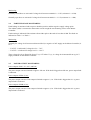
INPUT MONITORING
The function and the normal state of the inputs depends on the configuration.
Functions for inputs
Not in use
Evacuation input
Fault warning input
Fault in fire alarm router
Fault in fault warning router
Fault in extinguisher
Maintenance warning input
Technical alarm input
Silent technical alarm input
Day mode activation input
Delayed alarm enable input
Day mode and delayed alarm enable
General silence input
General reset input
Internal logic input
External logic input
Extinguisher activated input
Smoke vents activated input
Activation of customer led 1
Activation of customer led 2
Input
Normal open
Default
Default
Default
Default
Default
Default
Default
Default
Default for IOC input 1
Default for MC input 1
Default for MC input 2
Default for IOC input 2
Default for IOC input 3
Default for IOC input 4
Normal closed
Default
Default
Default
Default
Default
Default
Default
Default
Default
Default
Default
12 (21)
Monitoring:
Normally closed lines are activated if voltage level between terminals is > 3.0V (resistance is > 6 kΩ).
Normally open lines are activated if voltage level between terminals is < 3.0 V (resistance is < 6 kΩ).
3.4.
EARTH LEAKAGE MONITORING
Earth leakage is monitored with respect to both the positive and the negative supply voltage poles.
The cabinet (earth) is connected to the monitor circuit trough the two mounting screws in the Master
Controller.
Fault warning is indicated if the resistance from either pole to the earth is less than 20 kΩ. The faults are
indicated as "fault -" or "fault +".
Monitoring:
Normally the voltage level between cabinet and Gnd (ie. negative of 24V supply on the Master Controller) is
14 V.
− FAULT - is indicated if voltage level is < 7.8 V
− FAULT + is indicated if voltage level is > 19.6 V
These voltage levels are floated by factor Vsupply/27V where Vsupply is voltage level measured from eg. 24 V
supply terminals on the Master Controller.
3.5.
POWER OUTPUT MONITORING
Power outputs of MC, LC, ALC, and IOC:
The power output current is limited to approx. 650 mA. If the load is bigger than 650 mA, power output fault
is indicated.
Power outputs of PSA (2,2A):
The power output current of each output is limited to approx. 2,1 A. If the load is bigger than 2.1 A, power
output fault is indicated.
Power outputs of PSB (4,5A):
The power output current of each output is limited to approx. 4,2 A. If the load is bigger than 4.2 A, power
output fault is indicated.
13 (21)
3.6.
BATTERY, CHARGER AND MAINS MONITORING
The fault warnings of the battery, charger and mains.
Battery low voltage fault
If voltage level of battery is < 23 V . (E.g. during a long mains break).
Battery fault
If the battery circuit is broken (e.g. blown fuse or loose connectors).
Charger over voltage fault
If voltage level of charger is too high (> 32 V).
Charger fault
If mains is on and Control Panel doesn't get supply voltage from charger.
If control circuit of fast charge is out-of-order.
Mains fault
If mains is off for 30 min.
Battery low voltage, charger over voltage and mains fault monitoring:
The test is done at intervals of 100 ms.
Test sequence:
battery voltage Ubm is measured
charger voltage Ucm is measured
mains input is read
Fault limit
Ubm < 23 V in four consecutive measurings
Fault indication
Battery low voltage fault
Ucm > 32 V in four consecutive measurings
Charger over voltage fault
Mains off for 30 min.
Mains fault
14 (21)
Battery and charger fault monitoring:
The tests are done at the same time at intervals of 40 s and immediately after the fault reset. If “faulty” result
is measured, then the tests will be re-done at intervals of 100 ms, until four “faulty” result or one “ok” result
have been measured. The tests are not done if mains is off or charger is in over voltage condition. The
battery fault monitoring test is not done if charger fault is active.
Test sequence (battery fault monitoring):
- battery charge switch is opened
- battery discharge switch is closed
- 100 ms is waited
- 50 ms is waited
- battery voltage (discharged) Ubm(d) is measured
- battery discharge switch is opened
- battery charge switch is closed
Test sequence (charger fault monitoring):
- battery charge switch is opened
- 100 ms is waited
- if fast charge control is active
o charger voltage (fast charge) Ucm(f) is measured
o fast charge control is deactivated
o 50 ms is waited
o charger voltage (normal) Ucm(n) is measured
o fast charge control is activated
- If fast charge control is not active
o charger voltage (normal) Ucm(n) is measured
o fast charge control is activated
o 50 ms is waited
o charger voltage (fast charge) Ucm(f) is measured
o fast charge control is deactivated
- battery charge switch is closed
Fault limit
Ucm(f) – Ucm(n) < 0,5 V in four consecutive measurings
Fault indication
Charger fault
Ubm(d) < 21 V in four consecutive measurings
Battery fault
Battery charge control:
The battery charge switch is opened if charger voltage < 20 V. The battery charge switch is closed when
battery voltage > 20,5 V.
Fast charge control:
The fast charge control is activated if battery voltage < 23 V. The fast charge control is deactivated when
battery voltage > 23V for 72 h.
15 (21)
4.
PROGRAM MONITORING (System fault)
The internal system is supervised by the processor. The independent watch-dog will interrupt the running
program, if not updated by the processor at least every 1200 msec.
System faults are indicated on the display with steady "GENERAL FAULT" and "SYSTEM FAULT"
indicators and with an audible signal.
If the running processor cannot control the system the independent watch-dog lock the the system and the
system fault is indicated and fault routing output is activated on the Master Controller board.
If system fault is detected by software (eg. wrong check sum in configuration memory) system fault is
indicated and the fault routing output is activated on the Master Controller board and there is information on
the lcd display to describe the reason of system fault.
WARNING!
Normal operation of the fire control panel is stopped when a system fault is detected.
NOTE!
It is important that system fault texts on lcd-display (if available) are recorded by service person for
later fault analyzing.
The locked System fault indication may be removed only by pressing the restart buttons on the Master
Controller Unit or by turning off the power of the system by disconnecting the battery cable and the 30Vac
supply cable from the Power Supply Unit and after a few seconds turning on the power again.
5.
ACCESS LEVEL 3 (Service state) AND 4
The Control Panel is set into access level 3 (service state) or 4 by entering correct password from the user
panel. The Control Panel has to be set first into access level 3 before setting into access level 4.
Control Panel returns to access level 1 when the key is turned off or removed.
Functions in access level 3:
− The reset time of the fire alarm and prealarm is 5 sec. (normally 15 sec.).
− Detector loop may be disconnected (the voltage during disconnection between loop terminals is 0, but
there is no galvanic isolation between the loop and the control panel).
− Zone may be set to the test state. During zone test the alarms and fault warnings in tested zone are
indicated only on the LCD display. The outputs and other indicators are not activated.
− When a connected analog sensor is selected on the display the analog value received from that sensor is
displayed as the puls width in µs.
− The panel may be set to the configuration mode by setting the config jumpper on the Master Controller.
− The language of the user interface may be changed from the menu.
− The analysis of the loop communication may be selected from the menu.
− The detectors that has exceeded the maintenance level (“dirty detector”) may be called to the display.
− The event register may be erased.
Functions in access level 4:
− The alarm counter may be erased from the menu.
16 (21)
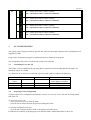
6.
SETTINGS ON THE COMPONENT BOARDS
Master Controller (MC).
Jumper
J2
Position
Function. Default settings are in bold face.
On -> Configuration state
Off -> Normal state
On -> Alarm device line control is pulsed
Off -> Alarm device line control is continuous
On -> Program update state
Off -> Normal state
On -> External power in use
Off -> External power not in use
J1
Four Input Output Controllers in panel
Three Input Output Controllers in panel
Two Input Output Controllers in panel
One Input Output Controllers in panel
J3
Four Loop Controllers in panel
Three Loop Controllers in panel
Two Loop Controllers in panel
One Loop Controller in panel
17 (21)
Loop Controller (LC) and Intellia loop Controller (ALC)
Jumper
Position
Function. Default settings are in bold face.
The address of Loop Controller is 1
J1, J2
The address of Loop Controller is 2
The address of Loop Controller is 3
The address of Loop Controller is 4
On -> Program update state
J3
Off -> Normal state
On -> Leds of loop devices blink
J4
Off -> Leds of loop devices not blink
Conventional Loop Controller (CLC)
Jumper
Position
Function. Default settings are in bold face.
The address of Loop Controller is 1
J1, J2
The address of Loop Controller is 2
The address of Loop Controller is 3
The address of Loop Controller is 4
Input Output Controller.
Jumper
J1
Position
Function. Default settings are in bold face.
The address of Input Output Controller is 1
J2
The address of Input Output Controller is 2
The address of Input Output Controller is 3
The address of Input Output Controller is 4
18 (21)
On -> Alarm device line 1 control is pulsed
J3
Off -> Alarm device line 1 control is continuous
On -> Alarm device line 2 control is pulsed
Off -> Alarm device line 2 control is continuous
On -> Alarm device line 3 control is pulsed
Off -> Alarm device line 3 control is continuous
On -> Alarm device line 4 control is pulsed
Off -> Alarm device line 4 control is continuous
7.
PC CONFIGURATION
The system can be configured with site specific data with a PC (Personal Computer) and a configuration tool
supplied by ESMI.
Usage of the configuration program is explained in the user manual of the program.
The configuration data can be read from and written to the FX panel.
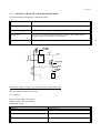
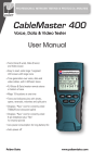
7.1.
Connecting a PC to the FX
The FX has a serial communication port using RS232 signal levels and including Rd and Td signals. No
handshake signals are needed.
To connect the PC to the FX you will need a specially made cable according to the following:
25-pole Dcontact
RxD 3
TxD 2
GND 7
7.2.
PC
9-pole D-contact
RxD 2
TxD 3
GND 5
----------------------------------------------------------
FX
Service terminal
on the Master Controller
TXD
RXD
GND
Preparing FX for configuration
To prepare the FX for configuration data transfer you have to set access level 3 and start the configuration
task in the FX.
To set access level 3 you:
− select 'current access level' from the menu
− press the 'Scroll' wheel and enter the password rolling the wheel.
To start the configuration task you:
− close the pins of jumper named CONF on the Master Controller board
FX indicates its readiness by displaying the text 'READY FOR CONFIGURATION' in the LCD.
19 (21)
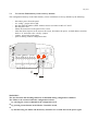
7.3.
To erase the Flash memory back to factory defaults
The configuration memory on the flash memory can be erased back to factory defaults by the following:
-
disconnect power from the panel
set “config”- jumper ON on MC
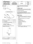
turn the panel ID number (HEX- address selector) switches on MC to E and F
turn the power ON
follow the instruction on the panel LCD- screen
when the reboot request can be seen on the screen, disconnect the power, set both address switches
back to “0” and remove the “config”- jumper
connect power back to the panel
panel is starting without configuration data
SA
E
F
WARNING!
The fire detection and alarming functions are disabled during configuration condition.
The FX has to be restarted when the configuration is done:
− by selecting the restart command in the configuration tool,
or
− by pressing restart button on the Master Controller board,
or
− by disconnecting the mains and the battery and after few seconds turn on the power again.
20 (21)
8.
TO UPDATE THE APPLICATION PROGRAM IN THE UNITS
The application program may be updated to Master Contoller (MC), Loop Controller (LC) and Intellia Loop
Controller (ALC) separately connecting the PC to the MC unit and download the application to the unit.
The application programs in Conventional Loop Controller (CLC), I/O controller (IOC), Power supply A
(PSA) and Power Supply B (PSB) may be downloaded only in factory. So the update of the program is done
by replacing the unit.
9.
RESTARTING THE SYSTEM
The system starts automatically when power is connected.
(To connect power to the panel, connect the 30Vac cable and battery cable to the Power Supply unit.)
The system can be restarted without power down – power up, by pressing the restart button on the Master
Controller Board.
10.
BOARD REPLACEMENT
NOTE!
Always de-energize the system by disconnecting the battery cable and the 30Vac cable from the Power
Supply unit before replacing a board.
A board is removed by:
- Loosening (two turns) two screws (type pozidrive 1) in both front corners.
- Moving the board first laterally ½ cm and then up ½ cm and then pulling it out laterally from the
mother board connector and the rack
A new board is installed in opposite order.
21 (21)
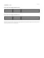
APPENDIX 1 - Fuses
Fuses on the Power supply board PSA (2,2A):
Fuse
BATT FUSE
MAIN FUSE
Type
T6.3A
T3.15
Protects
Battery , “+”pole
30Vac , the secondary circuit of transformer
Fuses on the Power supply board PSB (4,5A):
Fuse
BATT FUSE
MAIN FUSE
Type
T6.3A
T6.3A
Protects
Battery , “+”pole
30Vac , the secondary circuit of transformer
The short circuit protections in other power supply outputs and in alarm device outputs are not done by fuses
and those protections recover automatically.