1
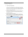
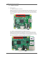
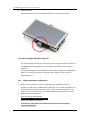
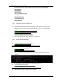
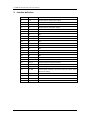
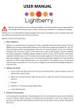
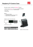
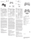
5" HDMI LCD with Resistive Touch User Manual 5" HDMI LCD with Resistive Touch User Manual Features 800×480 high resolution Directly-pluggable into Raspberry Pi 2 Model B (Pi model B requires additional HDMI cable) Drivers is provided for Pi and Pi 2 Can be used as HDMI display (without touch panel input as it require I/O interface). High quality immersion gold surface plating Content 5" HDMI LCD with Resistive Touch User Manual ....................................................................... 1 Features ........................................................................................................................... 1 1. Working with Raspberry Pi........................................................................................ 2 1.1 1.2 1.3 2. System image file programming....................................................................... 2 Hardware connection...................................................................................... 3 How to configure Raspbian image file .............................................................. 4 Interface definition .................................................................................................... 7 1 5" HDMI LCD with Resistive Touch User Manual 1. Working with Raspberry Pi 1.1 System image file programming In order to use the LCD with Raspberry Pi, you should configure the original system first. Of course, you can program a ready-to-use system image file to your Raspberry Pi board as well. In this section, we present the steps of image programming by taking the ready-to-use system image file programming as an example. And Section 1.3 describes how to configure original system. 1) Copy the file with the expansion name .img under the direction of IMAGE to your PC. (Under the direction of IMAGE, there are three system image files for Raspbian system, PIDORA system, and Raspbmc system respectively. And all of these file are in 2) 3) the expansion name of .img) Format your TF card with the SDFormatter.exe. Notices: The capability of TF card in used here should be more than 4GB. In this operation, a TF card reader is also required, which has to be purchased separately. Start the Win32DiskImager.exe, and select the system image file copied into your PC, then, click the button Write to program the system image file. 2 5" HDMI LCD with Resistive Touch User Manual 1.2 1) Hardware connection GPIO connection a) Raspberry Pi Model A+ connection Raspberry Pi Model A+ has 40 pins expanded GPIO header, while HDMI screen has 26 pins expanded header. The screen’s pins must connect to the Pi’s corresponding pins. The pins on Raspberry Pi Model A+ for screen connection are marked with red box as shown below. b) Raspberry Pi Model B+/Raspberry Pi 2 Model B connection Raspberry Pi Model B+/Raspberry Pi 2 Model B has 40 pins expanded GPIO header, while HDMI screen has 26 pins expanded header. The screen’s pins must connect to the Pi’s corresponding pins. The pins on Raspberry Pi Model B+/Raspberry Pi 2 Model B for screen connection are marked with red box as shown below. 3 5" HDMI LCD with Resistive Touch User Manual 2) HDMI connection Plug the HDMI connector in the HDMI interfaces of screen and main board. 1.3 How to configure Raspbian image file It is recommended to employ the ready-to-use system image file under the direction of /IMAGE/5inch_HDMI_Raspbian .img. The relative operations are presented in Section 1.1. The Raspbian image file downloaded from official website need further configurations before use. If you want to apply the original system image file, please read the following sections. 1.3.1 Display parameter configuration 1) 2) Enter the system terminal. Connect a keyboard and a HDMI displayer to the Raspberry Pi, and switch to HDMI display mode, then you can enter the Graphic User Interface directly to perform operations. Also, you can control the Raspberry Pi via network or serial communication, if no HDMI displayer and keyboard are in used. Modify the file /boot/config.txt Enter the command listed below: pi@raspberrypi ~ $sudo nano /boot/config.txt Make the modification as follows: # uncomment if hdmi display is not detected and composite is being output hdmi_force_hotplug=1 4 5" HDMI LCD with Resistive Touch User Manual # uncomment to force a specific HDMI mode (here we are forcing 800x480!) hdmi_group=2 hdmi_mode=1 hdmi_mode=87 hdmi_cvt 800 480 60 6 0 0 0 start_file=start_x.elf fixup_file=fixup_x.elf #gpu_mem=128 1.3.2 Touch parameter configuration 1) Copy the file \software\5inch_HDMI_LCD.tar.gz to any position you want in the Raspberry Pi system via network or U disk. And then, enter the command listed below: pi@raspberrypi ~ $tar xvf 5inch_HDMI_LCD.tar.gz pi@raspberrypi ~ $cd 5inch_HDMI_LCD/ pi@raspberrypi ~ $sudo ./5inch_HDMI_LCD 2) Restart the system, then the touch screen is ready to use. 1.3.3 Screen touch calibration 1) Install the screen touch calibration Demo: pi@raspberrypi ~ $cd 5inch_HDMI_LCD/ pi@raspberrypi ~ $sudo dpkg -i -B xinput-calibrator_0.7.5-1_armhf.deb 2) Enter the command listed below: pi@raspberrypi ~ $su pi pi@raspberrypi ~ $DISPLAY=:0.0 xinput_calibrator 3) 4) When the calibration finished, the new calibration data will be displayed in the terminal. Please get these data (marked with a red box) for future use. Enter the following command: pi@raspberrypi ~ $sudo mkdir /etc/X11/xorg.conf.d pi@raspberrypi ~ $sudo nano 5) /etc/X11/xorg.conf.d/99-calibration.conf Paste the data you get in step 3 into the terminal. 5 5" HDMI LCD with Resistive Touch User Manual Press the keys Ctrl+X, then select the option Y and press the key Enter to save the modification and exit. 6) Enter the command for system rebooting: pi@raspberrypi ~ $sudo reboot The touch configuration will be valid after rebooting the system. 6 5" HDMI LCD with Resistive Touch User Manual 2. Interface definition PIN NO. SYMBOL DESCRIPTION 1 3.3V Power positive (3.3V power input) 2 5V Power positive (5V power input) 3 NC NC 4 5V Power positive (5V power input) 5 NC NC 6 GND Ground 7 NC NC 8 NC NC 9 GND Ground 10 NC NC 11 NC NC 12 NC NC 13 NC NC 14 GND Ground 15 NC NC 16 NC NC 17 3.3V Power positive (3.3V power input) 18 NC NC 19 LCD_SI SPI data input of LCD/Touch Panel 20 GND Ground 21 TP_SO SPI data output of Touch Panel 22 TP_IRQ Touch Panel interrupt, low level while the Touch Panel detects touching 23 TP_SCK SPI clock of Touch Panel 24 NC NC 25 GND Ground 26 TP_CS Touch Panel chip selection, low active 7